US9205883B2 - Tank trailer having an adjustable kingpin assembly - Google Patents
Tank trailer having an adjustable kingpin assembly Download PDFInfo
- Publication number
- US9205883B2 US9205883B2 US14/095,619 US201314095619A US9205883B2 US 9205883 B2 US9205883 B2 US 9205883B2 US 201314095619 A US201314095619 A US 201314095619A US 9205883 B2 US9205883 B2 US 9205883B2
- Authority
- US
- United States
- Prior art keywords
- trailer
- pivot frame
- angular position
- pivot
- assembly
- Prior art date
- Legal status (The legal status is an assumption and is not a legal conclusion. Google has not performed a legal analysis and makes no representation as to the accuracy of the status listed.)
- Active, expires
Links
Images


Classifications
-
- B—PERFORMING OPERATIONS; TRANSPORTING
- B62—LAND VEHICLES FOR TRAVELLING OTHERWISE THAN ON RAILS
- B62D—MOTOR VEHICLES; TRAILERS
- B62D53/00—Tractor-trailer combinations; Road trains
- B62D53/04—Tractor-trailer combinations; Road trains comprising a vehicle carrying an essential part of the other vehicle's load by having supporting means for the front or rear part of the other vehicle
- B62D53/08—Fifth wheel traction couplings
- B62D53/0842—King pins
- B62D53/085—King pins fitted with anti-coupling devices, pivotal or retractable king pins, e.g. to prevent theft
-
- B—PERFORMING OPERATIONS; TRANSPORTING
- B60—VEHICLES IN GENERAL
- B60D—VEHICLE CONNECTIONS
- B60D1/00—Traction couplings; Hitches; Draw-gear; Towing devices
- B60D1/01—Traction couplings or hitches characterised by their type
- B60D1/015—Fifth wheel couplings
-
- B—PERFORMING OPERATIONS; TRANSPORTING
- B62—LAND VEHICLES FOR TRAVELLING OTHERWISE THAN ON RAILS
- B62D—MOTOR VEHICLES; TRAILERS
- B62D53/00—Tractor-trailer combinations; Road trains
- B62D53/04—Tractor-trailer combinations; Road trains comprising a vehicle carrying an essential part of the other vehicle's load by having supporting means for the front or rear part of the other vehicle
- B62D53/06—Semi-trailers
- B62D53/061—Semi-trailers of flat bed or low loader type or fitted with swan necks
- B62D53/062—Semi-trailers of flat bed or low loader type or fitted with swan necks having inclinable, lowerable platforms; Lift bed trailers; Straddle trailers
-
- B—PERFORMING OPERATIONS; TRANSPORTING
- B62—LAND VEHICLES FOR TRAVELLING OTHERWISE THAN ON RAILS
- B62D—MOTOR VEHICLES; TRAILERS
- B62D53/00—Tractor-trailer combinations; Road trains
- B62D53/04—Tractor-trailer combinations; Road trains comprising a vehicle carrying an essential part of the other vehicle's load by having supporting means for the front or rear part of the other vehicle
- B62D53/08—Fifth wheel traction couplings
- B62D53/0842—King pins
Definitions
- the present invention relates generally to trailers and, more particularly, to trailer kingpin assemblies.
- Trailers commonly include a kingpin configured to attach to a fifth wheel assembly on a truck or tractor.
- the engagement between the fifth wheel assembly and the kingpin enables the truck or tractor to securely tow the trailer.
- Some conventional trailers include an adjustable kingpin assembly configured to pivot to adjust the ground clearance of the trailer.
- These adjustable kingpin assemblies may include a series of airbags or bladders configured to adjust the position of the kingpin assembly to achieve the desired ground clearance of the trailer. Accordingly, the adjustable kingpin assemblies enable the trailer to be positioned on the ground at a worksite, such as a hydraulic fracturing site, and then lifted off of the ground to facilitate transportation of the trailer to another location.
- the adjustable kingpin assemblies may also be configured to adjust the trailer between a relatively low ground clearance position and a relatively higher ground clearance position. For instance, it may be desirable to adjust the trailer into a relatively lower ground clearance position when the trailer is being transported on a highway, so that the trailer may safely pass under overpasses and through tunnels. In contrast, it may be desirable to adjust the trailer into a relatively higher ground clearance position when the trailer is being transported off-road or on other uneven terrain.
- Conventional kingpin assemblies also include a ratchet mechanism configured to lock the adjustable kingpin assembly into the desired position based upon the desired ground clearance of the trailer.
- the ratchet mechanisms on conventional adjustable kingpin assemblies are prone to wear, which may cause the adjustable kingpin assembly to prematurely fail.
- the engagement between the airbags and conventional adjustable kingpin assemblies is not completely maintained as the conventional kingpin assembly pivots into different opinions (i.e., conventional kingpin assemblies are not configured to compensate for the different angles between the kingpin assembly and the airbags due to the rotation of the kingpin assembly into different positions).
- Such angular misalignment between the airbags and the adjustable kingpin assembly may reduce the efficacy of the airbags or bladders in pivoting the kingpin assembly into different angular positions and may cause premature wear and failure of the airbags.
- the trailer includes a pivot frame including a kingpin pivotally coupled to the trailer.
- the pivot frame is configured to pivot between a first angular position and a second angular position to adjust a ground clearance of the trailer.
- the trailer also includes a rocker plate assembly pivotally coupled to the pivot frame, and at least one bladder engaging the rocker plate assembly to rotate the pivot frame between the first angular position and the second angular position.
- the rocker plate assembly is configured to pivot to compensate for the pivoting of the pivot frame between the first and second angular positions.
- the trailer may be any suitable type of trailer, such as a fluid storage tank.
- the trailer also includes at least one clevis coupled to the trailer.
- the pivot frame is pivotally coupled to the at least one clevis such that the pivot frame is configured to pivot between the first and second angular positions.
- the trailer includes a support assembly coupled to the trailer.
- the support assembly is configured to support the at least one bladder.
- the trailer further includes at least one spring-loaded latch pin configured to selectively lock the pivot frame into the first angular position and the second angular position to set the desired ground clearance of the trailer.
- the trailer also includes at least one latch bracket coupled to the trailer.
- the latch bracket is configured to receive the at least one spring-loaded latch pin.
- the trailer in another embodiment, includes a pivot frame including a kingpin pivotally coupled to the trailer.
- the pivot frame is configured to pivot between a first angular position and a second angular position to adjust a ground clearance of the trailer.
- the trailer also includes at least one bladder configured to rotate the pivot frame between the first angular position and the second angular position and at least one spring-loaded latch pin configured to selectively lock the pivot frame into the first angular position and the second angular position to set the desired ground clearance of the trailer.
- the at least one spring-loaded latch pin includes a pin configured to slide between a latched position and an unlatched position.
- the pin includes a primary rod and at least one lock-out rod coupled to the primary rod.
- the at least one lock-out rod is configured to lock the pin in the unlatched position.
- the at least one spring-loaded latch pin further includes a latch bracket defining a keyhole-shaped opening.
- the at least one lock-out rod is configured to pass through the keyhole-shaped opening when the pin is in the latched position and is configured not to pass through the keyhole-shaped opening when the pin is in the unlatched position.
- the at least one spring-loaded latch pin further includes at least one guide pin coupled to the pin and a spring wound around the at least one guide pin. The spring is configured to bias the pin into the latched position.
- FIGS. 1A-1C are perspective, side, and front views, respectively, of an adjustable kingpin assembly coupled to a tank trailer according to one embodiment of the present disclosure
- FIGS. 2A-2C are bottom, side, and front views, respectively, of the tank trailer of FIGS. 1A-1C ;
- FIGS. 3A and 3B are a side view and a front view, respectively, of a clevis according to one embodiment of the present disclosure
- FIG. 3C is a side view of a hinge plate according to one embodiment of the present disclosure.
- FIG. 3D is a front view of a hinge gusset according to one embodiment of the present disclosure.
- FIGS. 4A and 4B are a side view and a front view, respectively, of a latch assembly according to one embodiment of the present disclosure
- FIG. 4C is a side view of a latch plate according to one embodiment of the present disclosure.
- FIG. 4D is a top view of a latch support brace according to one embodiment of the present disclosure.
- FIGS. 5A-5C are a side view of a side support plate, a bottom view of a mounting plate, and a front view of a weld plate, respectively, according to one embodiment of the present disclosure
- FIGS. 6A and 6B are lower and upper perspective views, respectively, of a pivot frame according to one embodiment of the present disclosure
- FIGS. 6C and 6D are a top view and a cross-sectional view, respectively, of the pivot frame of FIGS. 6A and 6B ;
- FIGS. 7A and 7B are a front view and a side view of a rocker plate assembly according to one embodiment of the present disclosure
- FIGS. 7C , 7 D, and 7 E are a bottom view of an upper airbag mount plate, a side view of a gusset, and a front view of a stiffener, respectively, according to one embodiment of the present disclosure
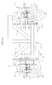
- FIG. 8A is a front view of a spring-loaded latch pin assembly in an unlatched position and a spring-loaded latch pin assembly in a latched position, according to one embodiment of the present disclosure.
- FIGS. 8B-8H are views of a pin, a handle plate, a handle, a latch bracket, a latch plate, a guide pin, and a stop ring, respectively, according to one embodiment of the present disclosure.
- the present disclosure is directed to various embodiments of an adjustable kingpin assembly pivotally coupled to a trailer.
- the adjustable kingpin assembly is configured to be detachably coupled to a fifth wheel assembly on a truck or tractor such that the truck or tractor may securely tow the trailer.
- the adjustable kingpin assembly is configured to pivot into two or more different angular positions to achieve a desired ground clearance of the trailer.
- the adjustable kingpin assembly is configured to compensate for the angular rotation of the adjustable kingpin assembly to maintain flush contact with a series of airbags or bladders configured to pivot the kingpin assembly into the different angular positions.
- the adjustable kingpin assembly is configured to be selectively locked into the different angular positions by one or more spring-loaded latch pins.
- an adjustable kingpin assembly 100 includes a pivot frame 101 pivotally coupled to a trailer 102 , at least one bladder or airbag 126 configured to rotatably drive the pivot frame 101 into two or more different angular positions, and at least one spring-loaded latch pin assembly 103 (see FIG. 8A ) configured to selectively lock the pivot frame 101 into the different angular positions.
- Rotation (arrow 104 ) of the pivot frame 101 is configured to adjust a ground clearance of the trailer 102 when the adjustable kingpin assembly 100 is coupled to a fifth wheel assembly on a truck or tractor (i.e., the rotation (arrow 104 ) of the pivot frame 101 is configured to lift a front end of the trailer 102 off the ground by a desired height so that the trailer 102 may be towed by the truck or tractor).
- the trailer 102 is a fluid storage tank trailer 102 having a first vertical sidewall 105 , a second vertical sidewall 106 spaced apart from the first vertical sidewall 105 , a horizontal base 107 extending between lower ends of the vertical sidewalls 105 , 106 , a roof 108 extending between upper ends of the vertical sidewalls 105 , 106 , and a vertical front wall 109 extending between forward ends of the vertical sidewalls 105 , 106 .
- the fluid storage tank trailer 102 also includes an intermediate vertical wall 110 and an intermediate horizontal wall 111 . Together, the intermediate walls 110 , 111 define a cavity 112 configured to house the adjustable kingpin assembly 100 .
- a portion of the fluid storage tank trailer 102 overhangs the cavity 112 and the adjustable kingpin assembly 100 housed therein.
- the adjustable kingpin assembly 100 is coupled to a fluid storage tank trailer 102
- the adjustable kingpin assembly 100 of the present disclosure may be attached to any other suitable type of trailer 102 .
- the tank trailer 102 also includes a plurality of longitudinal support members 113 and a plurality of transverse support members 114 coupled to the intermediate horizontal wall 111 .
- the trailer 102 also includes a series of vertical support members 115 coupled to the intermediate vertical wall 110 .
- the support members 113 , 114 , 115 may have any suitable shape, such as, for instance, square or rectangular posts, I-beams, C-channels, or square or rectangular tubing. Additionally, the support members 113 , 114 , 115 may be coupled to the intermediate walls 110 , 111 by any suitable means, such as, for instance, welding, bonding, fastening, or any combination thereof. As described in more detail below, the support members 113 , 114 , 115 are configured to facilitate attachment of the adjustable kingpin assembly 100 to the tank trailer 102 .
- the adjustable kingpin assembly 100 also includes a pair of clevises 116 coupled to, and extending downward from, the intermediate horizontal wall 111 of the tank trailer 102 .
- the tank trailer 102 includes two devises 116
- the trailer 102 may include any other suitable number of clevises 116 , such as, for instance, from one to four clevises 116 .
- the devises 116 are configured to pivotally couple the pivot frame 101 to the tank trailer 102 such that the pivot frame 101 may rotate (arrow 104 ) into different angular positions and thereby adjust the ground clearance of the front end of the tank trailer 102 .
- each clevis 116 includes a pair of spaced apart hinge plates 117 , 118 and a plurality of hinge gussets 119 extending between and interconnecting the hinge plates 117 , 118 .
- each clevis 116 includes three hinge gussets 119 , although in one or more alternate embodiments, each clevis 116 may include any other suitable number of hinge gussets 119 , such as, for instance, from one to five hinge gussets 119 .
- each hinge gusset 119 is a generally rectangular plate, although the hinge gussets 119 may have any other suitable shape and still fall within the scope and spirit of the present disclosure.
- Each hinge gusset 119 defines a rectangular notch 120 in an upper edge 121 of the hinge gusset 119 .
- the notches 120 in the hinge gussets 119 are configured to receive the longitudinal support members 113 on the intermediate horizontal wall 111 of the tank trailer 102 .
- the hinge gussets 119 may be coupled to the intermediate horizontal wall 111 and/or the longitudinal support members 113 of the tank trailer 102 by any suitable means, such as, for instance, welding, bonding, fastening, or any combination thereof.
- each hinge plate 117 , 118 is a generally triangular plate, although the hinge plates 117 , 118 may have any other suitable shape and still fall within the scope and spirit of the present disclosure.
- Each hinge plate 117 , 118 defines a rectangular notch 122 in an upper edge 123 of the hinge plate 117 , 118 .
- the rectangular notches 122 in the hinge plates 117 , 118 are configured to receive one of the transverse support members 114 on the intermediate horizontal wall 111 of the tank trailer 102 .
- the hinge plates 117 , 118 may be coupled to the intermediate horizontal wall 111 and/or the transverse support members 114 of the tank trailer 102 by any suitable means, such as, for instance, welding.
- Each hinge plate 117 , 118 also defines an opening 124 (e.g., a hole).
- the openings 124 in the hinge plates 117 , 118 are each configured to receive a bushing 125 (e.g., a tubing bushing).
- the bushings 125 accept and support one or more shafts about which the pivot frame 101 is configured to pivot (arrow 104 ) into different angular positions.
- the adjustable kingpin assembly 100 also includes a latch assembly 130 coupled to, and extending downward from, the intermediate horizontal wall 111 of the tank trailer 102 .
- the latch assembly 130 is configured to enable a user to selectively lock the pivot frame 101 into a desired angular position to achieve a desired ground clearance of the front end of the tank trailer 102 .
- the latch assembly 130 includes a pair of spaced apart latch brackets 131 , 132 , a transverse brace 133 extending between and interconnecting the latch brackets 131 , 132 , a rear support stiffener 134 extending along the transverse brace 133 , a vertical brace 135 extending between the transverse brace 133 and the intermediate horizontal wall 111 of the tank trailer 102 , and a pair of angled braces 136 , 137 extending between the transverse brace 133 and the intermediate horizontal wall 111 of the tank trailer 102 .
- the latch assembly 130 may have any other suitable number of braces 133 , 135 , 136 , 137 , such as, for instance, from one to six braces. Additionally, the braces 133 , 135 , 136 , 137 may have any other suitable configuration. The braces 133 , 135 , 136 , 137 may have any suitable shapes, such as, for instance, square or rectangular posts, I-beams, C-channels, or square or rectangular tubing.
- the rear support stiffener 134 is a rectangular plate, although the rear support stiffener 134 may have any other suitable shape, such as, for instance, triangular or semi-circular, and still fall within the scope and spirit of the present disclosure.
- each latch bracket 131 , 132 is a generally trapezoidal plate, although the latch brackets 131 , 132 may have any other suitable shape and still fall within the scope and spirit of the present disclosure.
- Each of the latch brackets 131 , 132 also defines a rectangular notch 138 in an upper edge 139 of the latch bracket 131 , 132 .
- the rectangular notches 138 in the latch brackets 131 , 132 are configured to receive one of the transverse support members 114 on the intermediate horizontal wall 111 of the tank trailer 102 .
- the latch brackets 131 , 132 may be coupled to the intermediate horizontal wall 111 and/or one of the transverse support members 114 of the trailer 102 by any suitable means, such as, for instance, welding, bonding, fastening, or any combination thereof.
- each latch bracket 131 , 132 also defines a plurality of openings (e.g., holes).
- each latch bracket 131 , 132 defines a lower opening 140 , a middle opening 141 , and an upper opening 142 .
- the lower, middle, and upper openings 140 , 141 , 142 are defined along an arc having a center point concentric with an axis of rotation of the pivot frame 101 .
- each latch bracket 131 , 132 in the illustrated embodiment defines three openings 140 , 141 , 142
- each latch bracket 131 , 132 may define any other suitable number of openings, such as, for instance, from two to five openings.
- Each of the openings 140 , 141 , 142 in the latch brackets 131 , 132 is configured to receive a bushing (e.g., a tube bushing).
- each latch bracket 131 , 132 includes a lower bushing 143 , a middle bushing 144 , and an upper bushing 145 received in the lower opening 140 , the middle opening 141 , and the upper opening 142 , respectively.
- Each pair of openings 140 , 141 , 142 and corresponding bushings 143 , 144 , 145 in the latch brackets 131 , 132 is associated with a different angular position of the pivot frame 101 (i.e., the pair of lower openings 140 and lower bushings 143 , the pair of middle openings 141 and middle bushings 144 , and the pair of upper openings 142 and upper bushings 145 each correspond to a different angular position of the pivot frame 101 ).
- the openings 140 , 141 , 142 and bushings 143 , 144 , 145 in the latch brackets 131 , 132 are configured to receive the spring-loaded latch pin assemblies 103 to lock the pivot frame 101 into the desired angular position.
- pivoting (arrow 104 ) the pivot frame 101 into different angular positions is configured to adjust the ground clearance of the front end of the tank trailer 102 .
- the latch assembly 130 is configured such that when the pivot frame 101 is coupled to the pair of lower openings 140 and corresponding lower bushings 143 in the latch assembly 130 by the spring-loaded latch pin assemblies 103 , the front end of the tank trailer 102 rests on the ground.
- the latch assembly 130 is configured such that when the pivot frame 101 is coupled to the pair of middle openings 141 and corresponding middle bushings 144 in the latch assembly 130 , the front end of the tank trailer 102 has a ground clearance of approximately 10 inches.
- the latch assembly 130 is configured such that when the pivot frame 101 is coupled to the pair of upper openings 142 and corresponding upper bushings 145 in the latch assembly 130 , the front end of the trailer 102 has a ground clearance of approximately 16 inches.
- the openings 140 , 141 , 142 and corresponding bushings 143 , 144 , 145 in the latch assembly 130 may be arranged such that the pivot frame 101 is configured to lift the front end of the trailer 102 to achieve any other desired ground clearances.
- the adjustable kingpin assembly 100 also includes a support assembly 150 coupled to the intermediate vertical wall 110 of the tank trailer 102 .
- the support assembly 150 supports the one or more bladders or airbags 126 that are configured to rotate (see arrow 104 in FIG. 1B ) the pivot frame 101 into different angular positions.
- the support assembly 150 includes a mounting plate 151 , a pair of side support plates 152 , 153 on opposite ends of the mounting plate 151 , and a pair of gussets 154 , 155 (see FIGS.
- the support assembly 150 also includes a pair of rectangular weld plates 157 , 158 provided between the intermediate vertical wall 110 of the tank trailer 102 and the pair of gussets 154 , 155 , respectively.
- the weld plates 157 , 158 are configured to facilitate attachment of the gussets 154 , 155 to the intermediate vertical wall 110 of the tank trailer 102 .
- the mounting plate 151 includes a plurality of openings 159 (e.g., holes) configured to receive fasteners securing the one or more bladders or airbags 126 to an upper surface 160 of the mounting plate 151 .
- the side support plates 152 , 153 are triangular, although in one or more alternate embodiments, the side support plates 152 , 153 may have any other suitable shape, such as, for instance, rectangular.
- the side support plates 152 , 153 may be coupled to the intermediate vertical wall 110 and/or the vertical support members 115 on the intermediate vertical wall 110 of the tank trailer 102 .
- the support assembly 150 may be coupled to the tank trailer 102 by any suitable means, such as, for instance, welding, bonding, fastening, or any combination thereof.
- the pivot frame 101 includes a first longitudinal member 161 and a second longitudinal member 162 spaced apart from the first longitudinal member 161 .
- the longitudinal members 161 , 162 may have any suitable shape, such as, for instance, square or rectangular posts, I-beams, C-channels, or square or rectangular tubing.
- each longitudinal member 161 , 162 is an I-beam having a top plate 163 , a bottom plate 164 , and a vertical web 165 extending between the top and bottom plates 163 , 164 , respectively.
- the longitudinal members 161 , 162 are bent or kinked such that front portions 166 of the longitudinal members 161 , 162 define an acute angle ⁇ relative to rear portions 167 of the longitudinal members 161 , 162 .
- the bent longitudinal members 161 , 162 increase the maximum potential angular rotation (arrow 104 ) of the pivot frame 101 about the clevises 116 , as illustrated in FIG. 1B .
- the longitudinal members 161 , 162 may strike the intermediate horizontal wall 111 of the tank trailer 102 when pivoting (arrow 104 ) into different angular positions, thereby limiting the maximum potential rotation (arrow 104 ) of the pivot frame 101 .
- the longitudinal members 161 , 162 may be straight.
- each longitudinal member 161 , 162 defines a central opening 168 (e.g., a hole).
- the central openings 168 are located at the bends between the front and rear portions 166 , 167 of the longitudinal members 161 , 162 , respectively.
- the central openings 168 are each configured to receive a bearing 169 .
- the pivot frame 101 is configured to pivot (arrow 104 ) about an axis extending through the bearings 169 .
- the pivot frame 101 also includes a pair of fish plates 170 , 171 coupled to inner and outer surfaces, respectively, of each of the webs 165 of the longitudinal members 161 , 162 .
- Each of the fish plates 170 , 171 also defines an opening 172 configured to align with the central openings 168 in the webs 165 of the longitudinal members 161 , 162 .
- the fish plates 170 , 171 are configured to reinforce the webs 165 of the longitudinal members 161 , 162 around the central openings 168 .
- the pivot frame 101 includes a pair of shear plates 173 , 174 coupled to the inner and outer surfaces, respectively, of each of the webs 165 of the longitudinal members 161 , 162 .
- each shear plate 173 , 174 includes a standoff plate 175 and a pair of flanges 176 , 177 on opposite ends of the standoff plate 175 .
- the shear plates 173 , 174 may be coupled to the webs 165 of the longitudinal members 161 , 162 by any suitable means, such as, for instance, welding, bonding, fastening, or any combination thereof.
- Each shear plate 173 , 174 also defines an opening 178 in the standoff plate 175 configured to align with the central openings 168 in the webs 165 of the longitudinal members 161 , 162 , respectively, and the openings 172 in the fish plates 173 , 174 .
- the openings 178 in the shear plates 173 , 174 are configured to receive and support the bearings 169 . Accordingly, each bearing 169 is configured to extend through the openings 178 in the shear plates 173 , 174 , the openings 172 in the fish plates 170 , 171 , and the central opening 168 in the web 165 of the longitudinal member 161 , 162 .
- each longitudinal member 161 , 162 also defines an aft opening 179 (e.g., a hole).
- the aft openings 179 in the longitudinal members 161 , 162 are each configured to receive an aft bushing 180 (e.g., a tube bushing).
- the aft bushings 180 are configured to rotatably support a rocker plate assembly 181 .
- the pivot frame 101 also includes an aft shear plate 182 coupled to each of the longitudinal members 161 , 162 .
- the aft shear plates 182 are coupled to the outer surfaces of the webs 165 of the longitudinal members 161 , 162 , respectively.
- the aft shear plates 182 may be coupled to the longitudinal members 161 , 162 , respectively, by any suitable means, such as, for instance, welding, bonding, fastening, or any combination thereof.
- Each of the aft shear plates 182 includes a standoff plate 183 and a pair of inwardly turned flanges 184 , 185 on opposite ends of the standoff plate 183 .
- the standoff plate 183 of each aft shear plate 182 also defines an opening 186 .
- the openings 186 in the aft shear plates 182 are configured to align with the aft openings 179 in the longitudinal members 161 , 162 , respectively.
- the openings 186 in the aft shear plates 182 are configured to receive and support the aft bushings 180 .
- the aft bushings 180 are configured to extend through the aft openings 179 in the webs 165 of the longitudinal members 161 , 162 and the aligned openings 186 in the aft shear plates 182 .
- each longitudinal member 161 , 162 also defines an intermediate opening 187 (e.g., a hole) located between the central openings 168 and the aft openings 179 .
- the intermediate openings 187 in the longitudinal members 161 , 162 are each configured to receive an intermediate bushing 188 (e.g., a tube bushing). As described below, and illustrated in FIG.
- the intermediate bushings 188 are configured to receive the spring-loaded latch pin assemblies 103 coupling the pivot frame 101 to the latch assembly 130 (i.e., the spring-loaded latch pin assemblies 103 are configured to extend through the intermediate bushings 188 in the pivot frame 101 and into either the pair of lower bushings 143 , middle bushings 144 , or upper bushings 145 in the latch assembly 130 to lock the pivot frame 101 into the desired angular position).
- the pivot frame 101 also includes an intermediate shear plate 189 coupled to each longitudinal member 161 , 162 .
- the intermediate shear plates 189 are coupled to the inner surfaces of the webs 165 of the longitudinal members 161 , 162 .
- the intermediate shear plates 189 may be coupled to the longitudinal members 161 , 162 by any suitable means, such as, for instance, welding, bonding, fastening, or any combination thereof.
- Each of the intermediate shear plates 189 includes a standoff plate 190 and a pair of outwardly turned flanges 191 , 192 on opposite ends of the standoff plate 190 .
- the standoff plate 190 of each intermediate shear plate 189 also defines an opening 193 .
- the openings 193 in the intermediate shear plates 189 are configured to align with the intermediate openings 187 in the longitudinal members 161 , 162 . Additionally, the openings 193 in the intermediate shear plates 189 are configured to receive and support the intermediate bushings 188 . Accordingly, the intermediate bushings 188 are configured to extend through the intermediate openings 187 in the webs 165 of the longitudinal members 161 , 162 and the openings 193 in the intermediate shear plates 189 .
- the pivot frame 101 also includes three transverse members 194 , 195 , 196 extending between and interconnecting the longitudinal members 161 , 162 .
- the pivot frame 101 may have any other suitable number of transverse members 194 , 195 , 196 , such as, for instance, from one to six transverse members, and still fall within the scope and spirit of the present disclosure.
- the transverse members 194 , 195 , 196 may have any suitable shape, such as, for instance, square or rectangular posts, I-beams, C-channels, or square or rectangular tubing.
- the pivot frame 101 also includes a nose bar 197 extending transversely between forward ends of the longitudinal members 161 , 162 .
- the pivot frame 101 also includes a kingpin plate 198 coupled to two of the transverse support members 195 , 196 and the nose bar 197 .
- the pivot frame 101 also includes a kingpin 199 extending downward from the kingpin plate 198 .
- the kingpin 199 is configured to be detachably connected to a fifth wheel on a truck or tractor such that the truck or tractor may tow the tank trailer 102 .
- the adjustable kingpin assembly 100 also includes the rocker plate assembly 181 coupled to a rear end of the pivot frame 101 .
- the one or more airbags or bladders 126 are configured to engage the rocker plate assembly 181 to drive the angular position of the pivot frame 101 (i.e., the engagement between the one or more airbags or bladders 126 and the rocker plate assembly 181 pivots (arrow 104 ) the pivot frame 101 into the desired angular position).
- the rocker plate assembly 181 is configured to compensate for the angular rotation (arrow 104 ) of the pivot frame 101 such that the one or more bladders 126 remain flush against the rocker plate assembly 181 .
- the rocker plate assembly 181 is configured to pivot (arrow 200 ) in a direction opposite to the direction of rotation (arrow 104 ) of the pivot frame 101 such that the position of the rocker plate assembly 181 relative to the one or more bladders 126 remains substantially constant.
- the rocker plate assembly 181 is configured to rotate (arrow 200 ) such that the rocker plate assembly 181 remains substantially parallel to the support assembly 150 coupled to the intermediate vertical wall 110 of the tank trailer 102 (see FIGS. 1A and 2B ), even as the pivot frame 101 pivots (arrow 104 ) into different angular positions.
- Maintaining alignment between the one or more bladders 126 and the portion of the pivot frame 101 that is engaged by the one or more bladders 126 is configured to maintain the efficacy of the one or bladders 126 in driving the pivot frame 101 into different angular positions. Otherwise, the angular misalignment between the one or more bladders 126 and the portion of the pivot frame 101 that is engaged by the one or more bladders 126 may reduce the efficacy of the bladders 126 in driving the pivot frame 101 into different angular positions. In one or more alternate embodiments, however, the adjustable kingpin assembly 100 may be provided without the rocker plate assembly 181 .
- the rocker plate assembly 181 includes an upper airbag mount plate 201 having a lower surface 202 and an upper surface 203 opposite the lower surface 202 .
- the rocker plate assembly 181 also includes a plurality of gussets 204 coupled to the upper surface 203 of the upper airbag mount plate 201 .
- the rocker plate assembly 181 further includes a stiffener 205 extending lengthwise along the upper surface 203 of the airbag mount plate 201 and coupled to each of the gussets 204 .
- the rocker plate assembly 181 includes six gussets 204
- the rocker plate assembly 181 may include any other suitable number of gussets 204 , such as, for instance, from one to ten gussets 204 .
- each gusset 204 is triangular, although the gussets 204 may have any other suitable shapes, such as, for instance, semi-circular or trapezoidal, and still fall within the scope and spirit of the present disclosure.
- Each gusset 204 also defines a circular opening 206 and a narrow slot 207 extending between the circular opening 206 and a lower edge 208 of the gusset 204 .
- the narrow slots 207 in the gussets 204 are configured to receive the stiffener 205 .
- the circular openings 206 in the gussets 204 are configured to receive a bushing 209 .
- a rod 210 about which the rocker plate assembly 181 is configured to pivot extends through the aft bushings 180 in the longitudinal members 161 , 162 of the pivot frame 101 and through the bushing 209 in the gussets 204 of the rocker plate assembly 181 (i.e., the rod 210 extends through the bushings 180 , 209 to pivotally couple the rocker plate assembly 181 to the pivot frame 101 ).
- the adjustable kingpin assembly 100 includes two spring-loaded latch pin assemblies 103 coupled to the pivot frame 101 .
- Each spring-loaded latch pin assembly 103 is configured to move between a latched position (shown by the right spring-loaded latch pin 103 assembly in FIG. 8A ) and an unlatched position (shown by the left spring-loaded latch pin assembly 103 in FIG. 8A ).
- the spring-loaded latch pin assemblies 103 are configured to detachably couple the pivot frame 101 to the latch assembly 130 to lock the pivot frame 101 into the desired angular position.
- the spring-loaded latch pin assemblies 103 extend through the intermediate openings 187 and corresponding intermediate bushings 188 in the pivot frame 101 and into the desired one of the three sets of openings 140 , 141 , 142 and corresponding bushings 143 , 144 , 145 in the latch assembly 130 (i.e., the spring-loaded latch pin assemblies 103 are configured to selectively couple the pivot frame 101 to the pair of lower openings 140 and lower bushings 143 , the pair of middle openings 141 and middle bushings 144 , or the pair of upper openings 142 and upper bushings 145 in the latch assembly 130 ).
- the spring-loaded latch pin assemblies 103 are disengaged from the latch assembly 130 such that the pivot frame 101 is configured to freely pivot (arrow 104 ) into any desired angular position (i.e., in the unlatched position, the spring-loaded latch pin assemblies 103 decouple the pivot frame 101 from the latch assembly 130 such that the one or more bladders or airbags 126 may freely drive the pivot frame 101 into any desired angular position).
- the primary cylindrical rod 214 is configured to extend through the intermediate bushings 188 in the pivot frame 101 and into a selected one of the bushings 143 , 144 , 145 in the latch assembly 130 when the spring-loaded latch pin 103 is in the latched position.
- the lock-out rods 215 are configured to lock the spring-loaded latch pin assemblies 103 in the unlatched position.
- each spring-loaded latch pin assembly 103 also includes a latch bracket 220 .
- the latch bracket 220 is C-channel having a faceplate 221 and a pair of legs 222 , 223 extending inward from opposite sides of the faceplate 221 .
- the legs 222 , 223 of the latch bracket 220 are coupled to the webs 165 of the longitudinal members 161 , 162 of the pivot frame 101 by any suitable means, such as, for instance, welding, bonding, fastening, or any combination thereof.
- the faceplate 221 of the latch bracket 220 defines a keyhole-shaped opening 224 , the significance of which is described below.
- the keyhole-shaped opening 224 in the latch bracket 220 includes a circular opening 225 and a pair of smaller arcuate notches 226 , 227 circumferentially disposed around the circular opening 225 .
- the faceplate 221 of the latch bracket 220 also defines a pair of openings 228 , 229 (e.g., holes) on opposite sides of the keyhole-shaped opening 224 .
- each spring-loaded latch pin assembly 103 also includes a diamond-shaped latch plate 230 coupled to the primary rod 214 .
- the diamond-shaped latch plate 230 defines a central opening 231 and a pair of openings 232 , 233 on opposite sides of the central opening 231 .
- the central opening 231 in the latch plate 230 receives the primary rod 214 .
- Each spring-loaded latch pin assembly 103 also includes a pair of guide pins or guide bolts 234 (see also FIG. 8G ).
- the guide bolts 234 extend through the openings 232 , 233 in the diamond-shaped latch plate 230 and the openings 228 , 229 in the latch bracket 220 .
- Each spring-loaded latch pin assembly 103 also includes a pair of compression springs 236 wound around the guide bolts 234 .
- the compression springs 236 are configured to bias the spring-loaded latch pin assembly 103 into the latched position.
- the diamond-shaped latch plate 230 is configured to slide along the guide bolts 234 as the spring-loaded latch pin assembly 103 moves between the latched position and the unlatched position.
- each spring-loaded latch pin assembly 103 also includes a stop ring 235 (see FIG. 8H ) coupled to an inner surface of the diamond-shaped latch plate 230 .
- the stop rings 235 are configured to about the intermediate bushings 188 in the pivot frame 101 when the spring-loaded latch pin assemblies 103 are in the latched position.
- a user may move the spring-loaded latch pin assembly 103 into the unlatched position by pulling the handle 213 outward with sufficient force to overcome the biasing force of the compressive springs.
- the lock-out rods 215 on the pin 211 are drawn outward through the arcuate notches 226 , 227 in the latch bracket 220 .
- the user may rotate the handle 213 , such as, for instance, approximately 90 degrees, into a rotated position, as shown in the left spring-loaded latch pin assembly 103 of FIG. 8A .
- the lock-out rods 215 are not aligned with the arcuate notches 226 , 227 in the latch bracket 220 . Instead, in the rotated position, the lock-out rods 215 are aligned with an outer surface of the latch bracket 220 . Accordingly, in the rotated position, the lock-out rods 215 are configured to abut the outer surface of the latch bracket 220 and thereby prevent the compressive springs 236 from forcing the pin 211 into the engaged position (i.e., the engagement between the lock-out rods 215 on the pin 211 and the outer surface of the latch bracket 220 is configured to lock the spring-loaded latch pin assembly 103 into the disengaged position). As described above, in the disengaged position, the one or more bladders 126 are able to freely rotate (arrow 104 ) the pivot frame 101 into any desired angular position.
- the user may return the spring-loaded latch pin assemblies 103 to the engaged position to lock the pivot frame 101 into the desired angular position.
- the user may rotate the handle 213 until the lock-out rods 215 on the pin 211 are aligned with the arcuate notches 226 , 227 in the latch bracket 220 . The user may then either release the handle 213 or guide the handle 213 inward.
- the biasing force of the compressive springs 236 is configured to draw the lock-out rods 215 inward through the arcuate notches 226 , 227 in the latch bracket 220 and force the primary rod 214 inward until it extends through the intermediate bushing 188 in the pivot frame 101 and into a selected one of the bushings 143 , 144 , 145 in the latch assembly 130 .
- the spring-loaded latch pin assemblies 103 detachably couple the pivot frame 101 to the latch assembly 130 and thereby lock the pivot frame 101 into the desired angular position.
Abstract
Description
Claims (19)
Priority Applications (1)
| Application Number | Priority Date | Filing Date | Title |
|---|---|---|---|
| US14/095,619 US9205883B2 (en) | 2013-12-03 | 2013-12-03 | Tank trailer having an adjustable kingpin assembly |
Applications Claiming Priority (1)
| Application Number | Priority Date | Filing Date | Title |
|---|---|---|---|
| US14/095,619 US9205883B2 (en) | 2013-12-03 | 2013-12-03 | Tank trailer having an adjustable kingpin assembly |
Publications (2)
| Publication Number | Publication Date |
|---|---|
| US20150151800A1 US20150151800A1 (en) | 2015-06-04 |
| US9205883B2 true US9205883B2 (en) | 2015-12-08 |
Family
ID=53264355
Family Applications (1)
| Application Number | Title | Priority Date | Filing Date |
|---|---|---|---|
| US14/095,619 Active 2034-01-26 US9205883B2 (en) | 2013-12-03 | 2013-12-03 | Tank trailer having an adjustable kingpin assembly |
Country Status (1)
| Country | Link |
|---|---|
| US (1) | US9205883B2 (en) |
Cited By (3)
| Publication number | Priority date | Publication date | Assignee | Title |
|---|---|---|---|---|
| US20170314986A1 (en) * | 2016-04-29 | 2017-11-02 | Air Ops, LLC | Trailer weighing system |
| US11634274B2 (en) | 2019-03-22 | 2023-04-25 | Sandbox Enterprises, Llc | Bulk fluid storage container |
| USD996800S1 (en) | 2020-02-27 | 2023-08-29 | Sandbox Enterprises, Llc | Stackable bulk fluid storage container |
Families Citing this family (1)
| Publication number | Priority date | Publication date | Assignee | Title |
|---|---|---|---|---|
| US10569606B2 (en) * | 2017-11-17 | 2020-02-25 | Strick Trailers, Llc | Plug for upper coupler of trailer |
Citations (16)
| Publication number | Priority date | Publication date | Assignee | Title |
|---|---|---|---|---|
| US2020161A (en) * | 1933-07-06 | 1935-11-05 | Highway Trailer Co | Trailer |
| US2441710A (en) * | 1944-09-21 | 1948-05-18 | William E Martin | Trailer |
| US2590210A (en) * | 1949-11-26 | 1952-03-25 | Rogers Brothers Corp | Detachable fluid pressure operated gooseneck for trailers |
| US2821409A (en) * | 1957-03-26 | 1958-01-28 | Youngstown Steel Car Corp | Fifth wheel suspension |
| US2826421A (en) * | 1954-08-02 | 1958-03-11 | William F Mueller | Trailer-tanker |
| GB860492A (en) * | 1958-07-01 | 1961-02-08 | Exxon Research Engineering Co | Improvements in towing vehicle and trailer combinations |
| US3095987A (en) * | 1959-11-19 | 1963-07-02 | Donald E Sable | Piggy-back transportation system |
| US3208770A (en) * | 1962-04-06 | 1965-09-28 | Anthony P Freitas | Fifth wheel pneumatic suspension system |
| US3884503A (en) * | 1973-01-24 | 1975-05-20 | Sverre Damm | Device for the interconnection of pulling vehicles and semitrailer |
| US4566716A (en) * | 1983-01-14 | 1986-01-28 | Renault Vehicules Industriels | Device for connecting a tractor to a semitrailer |
| US4961564A (en) * | 1987-10-02 | 1990-10-09 | Tartan Transportation Systems, Inc. | Air suspension apparatus |
| US5785341A (en) * | 1997-01-27 | 1998-07-28 | Advance Designed Systems, Inc. | Pneumatic isolator stabilizing assembly |
| US20080296867A1 (en) * | 2007-05-31 | 2008-12-04 | Bouwkamp Philip M | Pin box assembly with torsion resistant pivot and air spring |
| US7530591B2 (en) * | 2006-06-13 | 2009-05-12 | Cequent Performance Products, Inc. | Pin box assembly for trailer |
| US7712761B2 (en) * | 2006-06-13 | 2010-05-11 | Cequent Performance Products, Inc. | Extension coupling for interconnecting trailer and tow hitch |
| US7810831B2 (en) * | 2007-10-25 | 2010-10-12 | Jeff Wilkens | Vehicle hitch with multi-directional damping |
-
2013
- 2013-12-03 US US14/095,619 patent/US9205883B2/en active Active
Patent Citations (16)
| Publication number | Priority date | Publication date | Assignee | Title |
|---|---|---|---|---|
| US2020161A (en) * | 1933-07-06 | 1935-11-05 | Highway Trailer Co | Trailer |
| US2441710A (en) * | 1944-09-21 | 1948-05-18 | William E Martin | Trailer |
| US2590210A (en) * | 1949-11-26 | 1952-03-25 | Rogers Brothers Corp | Detachable fluid pressure operated gooseneck for trailers |
| US2826421A (en) * | 1954-08-02 | 1958-03-11 | William F Mueller | Trailer-tanker |
| US2821409A (en) * | 1957-03-26 | 1958-01-28 | Youngstown Steel Car Corp | Fifth wheel suspension |
| GB860492A (en) * | 1958-07-01 | 1961-02-08 | Exxon Research Engineering Co | Improvements in towing vehicle and trailer combinations |
| US3095987A (en) * | 1959-11-19 | 1963-07-02 | Donald E Sable | Piggy-back transportation system |
| US3208770A (en) * | 1962-04-06 | 1965-09-28 | Anthony P Freitas | Fifth wheel pneumatic suspension system |
| US3884503A (en) * | 1973-01-24 | 1975-05-20 | Sverre Damm | Device for the interconnection of pulling vehicles and semitrailer |
| US4566716A (en) * | 1983-01-14 | 1986-01-28 | Renault Vehicules Industriels | Device for connecting a tractor to a semitrailer |
| US4961564A (en) * | 1987-10-02 | 1990-10-09 | Tartan Transportation Systems, Inc. | Air suspension apparatus |
| US5785341A (en) * | 1997-01-27 | 1998-07-28 | Advance Designed Systems, Inc. | Pneumatic isolator stabilizing assembly |
| US7530591B2 (en) * | 2006-06-13 | 2009-05-12 | Cequent Performance Products, Inc. | Pin box assembly for trailer |
| US7712761B2 (en) * | 2006-06-13 | 2010-05-11 | Cequent Performance Products, Inc. | Extension coupling for interconnecting trailer and tow hitch |
| US20080296867A1 (en) * | 2007-05-31 | 2008-12-04 | Bouwkamp Philip M | Pin box assembly with torsion resistant pivot and air spring |
| US7810831B2 (en) * | 2007-10-25 | 2010-10-12 | Jeff Wilkens | Vehicle hitch with multi-directional damping |
Non-Patent Citations (1)
| Title |
|---|
| Photographs of Tank Trailer; Date Unknown, 3 pgs. |
Cited By (4)
| Publication number | Priority date | Publication date | Assignee | Title |
|---|---|---|---|---|
| US20170314986A1 (en) * | 2016-04-29 | 2017-11-02 | Air Ops, LLC | Trailer weighing system |
| US10094703B2 (en) * | 2016-04-29 | 2018-10-09 | Air Ops, LLC | Onboard trailer weighing system above a kingpin |
| US11634274B2 (en) | 2019-03-22 | 2023-04-25 | Sandbox Enterprises, Llc | Bulk fluid storage container |
| USD996800S1 (en) | 2020-02-27 | 2023-08-29 | Sandbox Enterprises, Llc | Stackable bulk fluid storage container |
Also Published As
| Publication number | Publication date |
|---|---|
| US20150151800A1 (en) | 2015-06-04 |
Similar Documents
| Publication | Publication Date | Title |
|---|---|---|
| US9205883B2 (en) | Tank trailer having an adjustable kingpin assembly | |
| US8272663B2 (en) | Tow assembly for heavy trucks | |
| US10661621B2 (en) | Fifth wheel hitch assembly having direct-mount mounting brackets | |
| GB2458312A (en) | Fence Panel Support Apparatus | |
| US10112661B2 (en) | Track hitching structure for wheeled crane and wheeled crane | |
| US20130069340A1 (en) | Oscillating kingpin structure for grain trailer | |
| US9839171B2 (en) | Agricultural land roller implement | |
| US2838338A (en) | Dismountable superstructure for transporting vehicles | |
| KR20090053473A (en) | The trailer making it easy to load wide plate | |
| US7204318B2 (en) | Tracking hitch assembly utilizing tractor lift arms as stabilizers | |
| US4180282A (en) | Front mounted ground supported tractor attachment | |
| US9039029B2 (en) | Transport trailer with adjustable-width swing arms | |
| US9139225B2 (en) | System and method for steering a trailer | |
| US6431577B1 (en) | Trailer hitch support body | |
| US20100201101A1 (en) | Trailer with adjustable ground clearance | |
| US20120056407A1 (en) | Hydraulically Operated Gooseneck Trailer and Latch Assembly | |
| US20150042073A1 (en) | System and Method for Positioning Sliding Plates on a Trailer | |
| US20160069102A1 (en) | Novel fence assembly | |
| US4106795A (en) | Ground supported front mounted tractor attachment | |
| US20150042066A1 (en) | System and Method for Slideably Positioning Swing Arm Sets of a Trailer | |
| US8075013B2 (en) | Mounting apparatus | |
| US6908094B1 (en) | Heavy duty towing hitch | |
| US9022408B2 (en) | System for transporting an over-sized load | |
| CA2810124C (en) | Agricultural land roller implement | |
| US20130328286A1 (en) | Fifth wheel assembly with automatic lockouts |
Legal Events
| Date | Code | Title | Description |
|---|---|---|---|
| AS | Assignment |
Owner name: SOUTHERN FRAC, LLC, TEXAS Free format text: ASSIGNMENT OF ASSIGNORS INTEREST;ASSIGNORS:BENNETT, NATHAN A.;LEONARD, JAMES D.;REEL/FRAME:031709/0305 Effective date: 20131202 |
|
| STCF | Information on status: patent grant |
Free format text: PATENTED CASE |
|
| MAFP | Maintenance fee payment |
Free format text: PAYMENT OF MAINTENANCE FEE, 4TH YR, SMALL ENTITY (ORIGINAL EVENT CODE: M2551); ENTITY STATUS OF PATENT OWNER: SMALL ENTITY Year of fee payment: 4 |
|
| AS | Assignment |
Owner name: WELLS FARGO BANK, NATIONAL ASSOCIATION, ILLINOIS Free format text: SECURITY INTEREST;ASSIGNORS:SOUTHERN FRAC, LLC;GFN MANUFACTURING CORPORATION;REEL/FRAME:056023/0202 Effective date: 20201214 |
|
| AS | Assignment |
Owner name: SOUTHERN FRAC, LLC, INDIANA Free format text: RELEASE BY SECURED PARTY;ASSIGNOR:WELLS FARGO BANK, NATIONAL ASSOCIATION;REEL/FRAME:056345/0979 Effective date: 20210525 |
|
| FEPP | Fee payment procedure |
Free format text: MAINTENANCE FEE REMINDER MAILED (ORIGINAL EVENT CODE: REM.); ENTITY STATUS OF PATENT OWNER: SMALL ENTITY |
|
| FEPP | Fee payment procedure |
Free format text: 7.5 YR SURCHARGE - LATE PMT W/IN 6 MO, SMALL ENTITY (ORIGINAL EVENT CODE: M2555); ENTITY STATUS OF PATENT OWNER: SMALL ENTITY |
|
| MAFP | Maintenance fee payment |
Free format text: PAYMENT OF MAINTENANCE FEE, 8TH YR, SMALL ENTITY (ORIGINAL EVENT CODE: M2552); ENTITY STATUS OF PATENT OWNER: SMALL ENTITY Year of fee payment: 8 |