US9194574B2 - Illumination light source - Google Patents
Illumination light source Download PDFInfo
- Publication number
- US9194574B2 US9194574B2 US14/444,302 US201414444302A US9194574B2 US 9194574 B2 US9194574 B2 US 9194574B2 US 201414444302 A US201414444302 A US 201414444302A US 9194574 B2 US9194574 B2 US 9194574B2
- Authority
- US
- United States
- Prior art keywords
- light source
- illumination light
- radiation
- radiation fins
- case
- Prior art date
- Legal status (The legal status is an assumption and is not a legal conclusion. Google has not performed a legal analysis and makes no representation as to the accuracy of the status listed.)
- Expired - Fee Related, expires
Links
Images


Classifications
-
- F—MECHANICAL ENGINEERING; LIGHTING; HEATING; WEAPONS; BLASTING
- F21—LIGHTING
- F21V—FUNCTIONAL FEATURES OR DETAILS OF LIGHTING DEVICES OR SYSTEMS THEREOF; STRUCTURAL COMBINATIONS OF LIGHTING DEVICES WITH OTHER ARTICLES, NOT OTHERWISE PROVIDED FOR
- F21V29/00—Protecting lighting devices from thermal damage; Cooling or heating arrangements specially adapted for lighting devices or systems
- F21V29/50—Cooling arrangements
- F21V29/502—Cooling arrangements characterised by the adaptation for cooling of specific components
- F21V29/507—Cooling arrangements characterised by the adaptation for cooling of specific components of means for protecting lighting devices from damage, e.g. housings
-
- F21K9/137—
-
- F—MECHANICAL ENGINEERING; LIGHTING; HEATING; WEAPONS; BLASTING
- F21—LIGHTING
- F21K—NON-ELECTRIC LIGHT SOURCES USING LUMINESCENCE; LIGHT SOURCES USING ELECTROCHEMILUMINESCENCE; LIGHT SOURCES USING CHARGES OF COMBUSTIBLE MATERIAL; LIGHT SOURCES USING SEMICONDUCTOR DEVICES AS LIGHT-GENERATING ELEMENTS; LIGHT SOURCES NOT OTHERWISE PROVIDED FOR
- F21K9/00—Light sources using semiconductor devices as light-generating elements, e.g. using light-emitting diodes [LED] or lasers
- F21K9/20—Light sources comprising attachment means
- F21K9/23—Retrofit light sources for lighting devices with a single fitting for each light source, e.g. for substitution of incandescent lamps with bayonet or threaded fittings
- F21K9/233—Retrofit light sources for lighting devices with a single fitting for each light source, e.g. for substitution of incandescent lamps with bayonet or threaded fittings specially adapted for generating a spot light distribution, e.g. for substitution of reflector lamps
-
- F—MECHANICAL ENGINEERING; LIGHTING; HEATING; WEAPONS; BLASTING
- F21—LIGHTING
- F21V—FUNCTIONAL FEATURES OR DETAILS OF LIGHTING DEVICES OR SYSTEMS THEREOF; STRUCTURAL COMBINATIONS OF LIGHTING DEVICES WITH OTHER ARTICLES, NOT OTHERWISE PROVIDED FOR
- F21V29/00—Protecting lighting devices from thermal damage; Cooling or heating arrangements specially adapted for lighting devices or systems
- F21V29/50—Cooling arrangements
- F21V29/70—Cooling arrangements characterised by passive heat-dissipating elements, e.g. heat-sinks
- F21V29/74—Cooling arrangements characterised by passive heat-dissipating elements, e.g. heat-sinks with fins or blades
- F21V29/76—Cooling arrangements characterised by passive heat-dissipating elements, e.g. heat-sinks with fins or blades with essentially identical parallel planar fins or blades, e.g. with comb-like cross-section
- F21V29/763—Cooling arrangements characterised by passive heat-dissipating elements, e.g. heat-sinks with fins or blades with essentially identical parallel planar fins or blades, e.g. with comb-like cross-section the planes containing the fins or blades having the direction of the light emitting axis
-
- F—MECHANICAL ENGINEERING; LIGHTING; HEATING; WEAPONS; BLASTING
- F21—LIGHTING
- F21V—FUNCTIONAL FEATURES OR DETAILS OF LIGHTING DEVICES OR SYSTEMS THEREOF; STRUCTURAL COMBINATIONS OF LIGHTING DEVICES WITH OTHER ARTICLES, NOT OTHERWISE PROVIDED FOR
- F21V29/00—Protecting lighting devices from thermal damage; Cooling or heating arrangements specially adapted for lighting devices or systems
- F21V29/50—Cooling arrangements
- F21V29/70—Cooling arrangements characterised by passive heat-dissipating elements, e.g. heat-sinks
- F21V29/83—Cooling arrangements characterised by passive heat-dissipating elements, e.g. heat-sinks the elements having apertures, ducts or channels, e.g. heat radiation holes
-
- F—MECHANICAL ENGINEERING; LIGHTING; HEATING; WEAPONS; BLASTING
- F21—LIGHTING
- F21Y—INDEXING SCHEME ASSOCIATED WITH SUBCLASSES F21K, F21L, F21S and F21V, RELATING TO THE FORM OR THE KIND OF THE LIGHT SOURCES OR OF THE COLOUR OF THE LIGHT EMITTED
- F21Y2115/00—Light-generating elements of semiconductor light sources
- F21Y2115/10—Light-emitting diodes [LED]
Definitions
- the present disclosure relates to illumination light sources which employ LEDs (Light Emitting Diodes) and the like as their light sources.
- LEDs Light Emitting Diodes
- FIG. 23 is a partial cross-sectional view of an illumination light source according to a related art.
- Illumination light source 1100 includes light emitting module 1110 having LEDs, circuit unit 1120 to make light emitting module 1110 light up, and case 1130 with a substantially-cylindrical shape to accommodate circuit unit 1120 .
- case 1130 On the outer wall of case 1130 , a plurality of radiation fins 1140 with a flat-plate shape is radially disposed.
- illumination light source 1100 is mounted on a ceiling and the like, in the vertically downward direction.
- heat is generated by such as light emitting module 1110 and circuit unit 1120 to warm surrounding air of illumination light source 1100 .
- This generates air streams around illumination light source 1100 , which flow in the vertically upward direction.
- the air streams flowing vertically upward can smoothly pass through gaps between radiation fins 1140 , which allows every radiation fin 1140 to perform heat exchange with outside air.
- An illumination light source includes a light emitting module having light emitting parts, a circuit unit, a base, a first housing member with a tube-like shape to accommodate the circuit unit, and a second housing member having a plurality of radiation fins.
- the light emitting module is electrically coupled with the circuit unit.
- the circuit unit is electrically coupled with the base.
- the light emitting module is disposed on one opening side of the tube-like first housing member, while the base is disposed on the other opening side.
- the second housing member includes a plurality of plate-like radiation fins, and a rotary ring body having a rotation axis agreeing with the center axis of the first housing member.
- the plurality of the radiation fins are in parallel with a virtual plane containing the rotation axis, and is disposed at intervals between each other in the direction orthogonal to the virtual plane.
- the inner wall of the rotary ring body surrounds the outer wall of the tube-like shape, so that the first housing member is combined with the second housing member.
- the second housing member is rotatably attached to the first housing member, about the center axis.
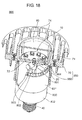
- FIG. 1 is a perspective view of an appearance configuration of an illumination light source according to the embodiment.
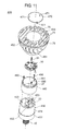
- FIG. 2 is an exploded perspective view of the illumination light source shown in FIG. 1 .
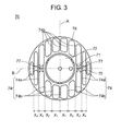
- FIG. 3 is an elevational view of a radiation member shown in FIG. 1 .
- FIG. 4 is a partial cross-sectional view of the illumination light source shown in FIG. 1 .
- FIG. 5A is a view of an exemplified mode of use of the illumination light source shown in FIG. 1 , which illustrates the state before the illumination light source is attached to a lighting fixture.
- FIG. 5B is a view of the exemplified mode of use of the illumination light source shown in FIG. 1 , which illustrates the state where a base of the illumination light source is being screwed into a socket.
- FIG. 5C is a view of the exemplified mode of use of the illumination light source shown in FIG. 1 , which illustrates the state where the orientation of a plurality of radiation fins is being adjusted.
- FIG. 5D is a view of the exemplified mode of use of the illumination light source shown in FIG. 1 , which illustrates the state after the orientation of the plurality of the radiation fins has been adjusted.
- FIG. 6A is a side-elevational view of the illumination light source shown in FIG. 1 , which illustrates air streams during lighting-up of the light source.
- FIG. 6B is an elevational view of the illumination light source shown in FIG. 1 , which illustrates the air streams during the lighting-up of the light source.
- FIG. 7 is a view of an illumination light source of a Comparative Example, which illustrates air streams during lighting-up of the light source.
- FIG. 8 is a perspective view of another illumination light source according to the embodiment.
- FIG. 9 is a cross-sectional side-elevation view of the another illumination light source shown in FIG. 8 .
- FIG. 10 is a perspective cross-sectional view of further another illumination light source according to the embodiment.
- FIG. 11 is an exploded perspective view of each of members which configure yet further another illumination light source according to the embodiment.
- FIG. 12 is a cross-sectional, side-elevational view of the yet further another illumination light source shown in FIG. 11 .
- FIG. 13 is a perspective view of another illumination light source according to the embodiment.
- FIG. 14 is an elevational view of the another illumination light source shown in FIG. 13 , which illustrates air streams during lighting-up of the light source.
- FIG. 15 is a perspective view of further another illumination light source according to the embodiment.
- FIG. 16 is a perspective view of yet further another illumination light source according to the embodiment.
- FIG. 17A is a side-elevational view of an appearance of the yet further another illumination light source shown in FIG. 16 .
- FIG. 17B is a side-elevational view of the appearance of the yet further another illumination light source shown in FIG. 17A , as viewed from a 90-degree-turned position.
- FIG. 18 is a partial cross-sectional view of an illumination light source of Modified Example 1 according to the embodiment.
- FIG. 19 is a cross-sectional view of the illumination light source shown in FIG. 18 , taken along a plane orthogonal to the center axis of a case.
- FIG. 20 is a partial cross-sectional view of an illumination light source of Modified Example 2 according to the embodiment.
- FIG. 21 is a cross-sectional, side-elevational view of the illumination light source shown in FIG. 20 .
- FIG. 22 is a perspective view of an illumination light source of Modified Example 3 according to the embodiment.
- FIG. 23 is a partial cross-sectional view of an illumination light source according to a related art.
- illumination light source 1100 shown in FIG. 23 heat exchange with outside air is sometimes inefficiently performed depending on the mounting posture of the light source to a lighting fixture and the like. Specifically, when illumination light source 1100 is mounted in a direction either slanting relative to or orthogonal to the vertical direction, air streams flowing vertically upward are less prone to flow due to blockage by plate surfaces of each of radiation fins 1140 . For this reason, the warmed air tends to stagnate inside gaps between radiation fins 1140 , resulting in a reduced efficiency of the heat radiation of each of radiation fins 1140 .
- FIG. 1 is a perspective view of an appearance configuration of illumination light source 1 according to the embodiment.
- the exterior of illumination light source 1 is configured with case 30 , base 40 , radiation member 50 , and cover 60 .
- Case 30 serves as a first housing member.
- Radiation member 50 serves as a second housing member.
- Case 30 has a substantially-cylindrical shape, and its center axis J is agreeing with the rotation axis of illumination light source 1 .
- Radiation member 50 includes a plurality of flat-plate radiation fins 74 .
- light emitting module 10 is accommodated which includes light emitting parts 12 .
- Cover 60 is a disk-like member which covers an opening disposed in the center portion of radiation member 50 .
- FIG. 2 is an exploded perspective view of each of members which configure illumination light source 1 .
- Light emitting module 10 includes mounting substrate 11 , a plurality of light emitting parts 12 disposed on mounting substrate 11 , and first connection terminal 13 a and second connection terminal 13 b (hereinafter, referred to as “connection terminals 13 a and 13 b ”).
- Mounting substrate 11 is a metal-base substrate which is configured with a resin plate and a metal plate, for example.
- a wiring pattern (not shown) is disposed on the upper surface of the substrate.
- Each of light emitting parts 12 is configured with a semiconductor light-emitting element such as an LED.
- Connection terminals 13 a and 13 b are electrically coupled with each of light emitting parts 12 via the wiring pattern.
- Circuit unit 20 includes circuit board 21 and various kinds of electronic components 22 mounted on circuit unit 20 .
- circuit board 21 On circuit board 21 , there are disposed first connection terminal 23 a and second connection terminal 23 b (hereinafter, referred to as “connection terminals 23 a and 23 b ”).
- Connection terminals 23 a and 23 b are electrically coupled with connection terminals 13 a and 13 b of light emitting module 10 , respectively, via lead wires 24 .
- circuit unit 20 is electrically coupled with base 40 via lead wires (not shown).
- Case 30 serving as the first housing member is substantially cylindrical, and includes large-diameter part 31 and small-diameter part 32 . Case 30 is rotationally symmetric about center axis J. In the inside of case 30 , circuit unit 20 is accommodated. Case 30 is formed with an electrical insulating material such as a resin or a ceramic, for example.
- Base 40 is a so-called Edison-type screw base, and is disposed at an opening end part on one end side of case 30 .
- Radiation member 50 serving as the second housing member is an integrally-molded article which is configured with a material excellent in heat conductivity, such as aluminum, copper, or iron. Radiation member 50 is operative to radiate heat to the outside, with the heat being generated from light emitting module 10 and circuit unit 20 . Radiation member 50 is configured with first radiation member 70 and second radiation member 80 , with the first and second members being combined with each other with screws 90 . Radiation member 50 has a rotation mechanism, the rotation axis of which is agreeing with center axis J of the first housing member.
- First radiation member 70 includes tube-like part 71 , bottom plate 72 , a plurality of radiation fins 74 , connection parts 75 , and rim part 76 .
- Tube-like part 71 is substantially cylindrical, and plays a role of a peripheral wall of the hollow part which accommodates light emitting module 10 therein.
- Bottom plate 72 has a substantially disk-like shape, and plays a role of a bottom wall of the hollow part which accommodates light emitting module 10 therein.
- a screw hole is disposed (not shown in FIG. 2 ). Screw 91 is inserted into hole 14 of light emitting module 10 , and then screw 91 is screwed into the screw hole to fix light emitting module 10 to bottom plate 72 .
- Radiation fins 74 each have a flat-plate shape, and are in parallel with one another. Specifically, as shown in the elevational view of FIG. 3 , each of radiation fins 74 is disposed in such a manner that: That is, the fin is in parallel with a virtual plane (hereinafter, referred to as plane A) which contains the rotation axis of tube-like part 71 , and is away from the next fin in the orthogonal direction (hereinafter, referred to as direction B) relative to plane A.
- plane A a virtual plane
- direction B orthogonal direction
- X 1 to X 4 represent gaps between adjacent radiation fins 74 .
- the gaps between adjacent radiation fins 74 are preferably set to become smaller, with increasing distance from the center to the adjacent fins in direction B (X 1 >X 2 >X 3 >X 4 ).
- Radiation fins 74 are preferably configured with first radiation fins 74 a and second radiation fins 74 b .
- First radiation fins 74 a are disposed to be outward away from the outer wall of tube-like part 71 , in direction B.
- Second radiation fins 74 b are disposed on the outer wall of tube-like part 71 .
- connection parts 75 are disposed between tube-like part 71 and first radiation fins 74 a .
- hole 77 is disposed to allow screw 90 to pass therethrough.
- Rim part 76 connects outer edges of radiation fins 74 . Rim part 76 plays a role in enhancing mechanical strength of the plurality of radiation fins 74 . In addition, rim part 76 serves as a hand grip for a user, either in attaching illumination light source 1 to a lighting fixture (not shown) or in rotating radiation member 50 .
- Second radiation member 80 includes rotary ring body 84 , projections 81 , and reduced-inner-diameter ring part 83 (for reduced-inner-diameter ring part 83 , see the inserted cross-sectional view of X-portion in the Figure).
- Rotary ring body 84 is substantially cylindrical. On one end part of rotary ring body 84 , a pair of projections 81 is formed. In each of projections 81 , screw hole 82 is formed. On the other end part of rotary ring body 84 , reduced-inner-diameter ring part 83 is formed which extends toward the center axis.
- Rotary ring body 84 is assembled such that its inner wall surrounds the outer wall of large-diameter part 31 of case 30 .
- the base 40 side of case 30 is first inserted from one end of second radiation member 80 , and then large-diameter part 31 of case 30 is fitted into rotary ring body 84 of second radiation member 80 .
- first radiation member 70 is arranged to overlap with second radiation member 80 , and projections 81 of second radiation member 80 are caused to abut on connection parts 75 of first radiation member 70 .
- screws 90 are passed through holes 77 of connection parts 75 , and then screws 90 are screwed into screw holes 82 of projections 81 .
- first radiation member 70 and second radiation member 80 are combined into a one-piece body, i.e. radiation member 50 .
- Cover 60 is a disk-like member for covering the opening of tube-like part 71 , which is operative to diffuse the light emitted from light emitting module 10 , thereby adjusting light distribution characteristics of illumination light source 1 .
- Cover 60 is formed with a translucent material including, for example, a glass and a resin material such as an acryl or a polycarbonate resin.
- FIG. 4 is a partial cross-sectional view of illumination light source 1 .
- one surface 83 a of reduced-inner-diameter ring part 83 of radiation member 50 is positioned to face end surface 31 a of large-diameter part 31 of case 30 , which thereby prevents case 30 from falling off.
- one surface 72 b of bottom plate 72 of radiation member 50 is positioned to face end surface 31 b of large-diameter part 31 . In this way, large-diameter part 31 is sandwiched between reduced-inner-diameter ring part 83 and bottom plate 72 , which thereby prevents radiation member 50 from moving relative to case 30 in both directions of center axis J.
- both rotary ring body 84 of second radiation member 80 and large-diameter part 31 of case 30 are substantially cylindrical.
- the rotation axis of rotary ring body 84 is agreeing with center axis J of large-diameter part 31 .
- both the inner diameter of rotary ring body 84 and the outer diameter of large-diameter part 31 are set to yield a slight clearance between the inner peripheral surface of rotary ring body 84 and the outer wall of large-diameter part 31 .
- radiation member 50 is rotatably held relative to case 30 . That is, the rotation mechanism is adopted between radiation member 50 and case 30 .
- restriction part 78 is formed to restrict the rotation, as shown in FIG. 4 .
- the outer side part of one end of large-diameter part 31 of case 30 includes stepped part 38 which has an outer diameter slightly smaller than that of large-diameter part 31 .
- stopper 37 is formed to restrict the allowable range of rotation of radiation member 50 .
- Illumination light source 1 is provided with one restriction part 78 and one stepped part 38 . With this configuration, the number of rotation of radiation member 50 relative to case 30 is restricted to be smaller than one.
- FIGS. 5A to 5D are views of an exemplified mode of use of illumination light source 1 .
- the downward direction on the paper sheets of the views refers to the vertically downward direction.
- FIG. 5A shows the state before illumination light source 1 is attached to lighting fixture 95 .
- lighting fixture 95 is mounted to wiring duct 96 installed on a ceiling or the like.
- the orientation of lighting fixture 95 can be freely changed.
- FIG. 5B shows the state where base 40 of illumination light source 1 is being screwed into socket 97 .
- the user grasps rim part 76 of radiation member 50 with user's hand, and applies a clockwise force to radiation member 50 .
- This causes radiation member 50 to rotate relative to case 30 .
- restriction 78 of radiation member 50 comes in contact with stopper 37 of case 30 , which thereby conveys the clockwise force applied to radiation member 50 to case 30 , resulting in the rotation of case 30 together with radiation member 50 as an integral whole.
- base 40 is screwed into socket 97 .
- case 30 may be grasped to directly apply the clockwise force to case 30 , which thereby screws base 40 into socket 97 .
- FIG. 5C shows the state where the orientation of the plurality of radiation fins 74 is being adjusted. After base 40 has been screwed into socket 97 , the user then applies a counterclockwise force to radiation member 50 so as to cause radiation member 50 to rotate relative to case 30 .
- FIG. 5D shows the state after the orientation of the plurality of radiation fins 74 has been adjusted.
- the adjustment is made such that the plate surfaces of all radiation fins 74 are oriented along the vertical direction.
- the plate surfaces of radiation fins 74 can be oriented along the vertical direction, by rotating radiation member 50 about center axis J of case 830 .
- the rotation torque required for the counterclockwise rotation of radiation member 50 relative to case 30 is adjusted to be smaller than the rotation torque required for the counterclockwise rotation of illumination light source 1 to remove the light source from socket 97 of lighting fixture 95 where the light source is mounted to the socket. For this reason, as shown in FIG. 5C , even when radiation member 50 is applied with the counterclockwise force to cause radiation member 50 to rotate relative to case 30 , base 40 does not rotate relative to socket 97 , retaining the state of being mounted to socket 97 .
- the rotation torque required for removing base 40 from socket 97 is larger than 5.0 Nm. Therefore, in this case, the rotation torque required for rotating radiation member 50 relative to case 30 may be set not smaller than 0.5 Nm and not larger than 5.0 Nm.
- the rotation torque required for rotating radiation member 50 relative to case 30 may be set not smaller than 0.5 Nm and not larger than 1.5 Nm. Therefore, in this case, the rotation torque required for rotating radiation member 50 relative to case 30 may be set not smaller than 0.5 Nm and not larger than 1.5 Nm.
- the rotation torque required for rotating radiation member 50 relative to case 30 can be set by adjusting, for example, the coefficient of friction between the outer wall of large-diameter part 31 of case 30 and the inner peripheral surface of rotary ring body 84 of radiation member 50 .
- the coefficient of friction between the outer wall of large-diameter part 31 and the inner peripheral surface of rotary ring body 84 can be changed by adjusting the factors including, for example: The degree of adhesion between the outer wall of large-diameter part 31 and the inner peripheral surface of rotary ring body 84 ; the area where the outer wall of large-diameter part 31 faces the inner peripheral surface of rotary ring body 84 ; the materials of large-diameter part 31 and rotary ring body 84 ; and the material of lubricant applied between the outer wall of large-diameter part 31 and the inner peripheral surface of rotary ring body 84 .
- FIGS. 6A and 6B are views of illumination light source 1 , which illustrate air streams during lighting-up of the light source.
- the downward direction on the paper sheets of the views refers to the vertically downward direction.
- air streams F 0 and F 1 are not interfered with by the outer wall of tube-like part 71 , where air stream F 0 flows through a gap between first radiation fins 74 a and air stream F 1 flows through a gap between first radiation fin 74 a and second radiation fin 74 b .
- the warmed air does not stagnate in the gaps between first radiation fins 74 a and the gaps between first radiation fins 74 a and second radiation fins 74 b .
- FIG. 7 is a view of illumination light source 100 of a Comparative Example, which illustrates air streams during lighting-up of the light source.
- Illumination light source 100 is different from illumination light source 1 in that a plurality of flat-plate radiation fins 140 is radially disposed on the outer wall of tube-like part 71 .
- the downward direction on the paper sheet of the view refers to the vertically downward direction.
- Both radiation fin 140 a and radiation fin 140 b are disposed at locations substantially vertically downward relative to the outer wall of tube-like part 71 .
- Air stream F 4 which flows into a gap between radiation fin 140 a and radiation fin 140 b disposed at the locations, is interfered with by the outer wall of tube-like part 71 . For this reason, the air warmed via the heat exchange with radiation fin 140 a and radiation fin 140 b , is caused to stagnate in the gap between radiation fin 140 a and radiation fin 140 b (Cloud symbol S 2 ).
- illumination light source 1 includes light emitting module 10 , circuit unit 20 , base 40 , case 30 (the first housing member), and radiation member 50 (the second housing member).
- Light emitting parts 12 are electrically coupled with circuit unit 20 .
- Circuit unit 20 is electrically coupled with base 40 .
- Case 30 has a tube-like shape, and accommodates circuit unit 20 .
- Tube-like case 30 includes the openings at both ends thereof, and includes the light emitting module disposed in one of the openings and the base disposed in the other.
- Radiation member 50 includes rotary ring body 84 and the plurality of plate-like radiation fins 74 .
- Rotary ring body 84 has the rotation axis agreeing with center axis J of case 30 .
- Plate-like radiation fins 74 are in parallel with one virtual plane A containing the rotation axis, and are disposed at intervals between each other in direction B orthogonal to plane A.
- radiation member 50 is combined with case 30 such that the inner wall of rotary ring body 84 surrounds the outer wall of case 30 . That is, radiation member 50 is rotatably attached to case 30 , about center axis J.
- the rotation mechanism of radiation member 50 rotatable about center axis J may be adopted between radiation member 50 and case 30 , as in the case of illumination light source 1 .
- the rotation mechanism may be adopted in at least one of case 30 and radiation member 50 .
- the plate surfaces of radiation fins 74 can be oriented along the vertical direction by rotating radiation member 50 about center axis J of case 30 .
- This configuration permits a smooth flow of the warmed air.
- first radiation fins 74 a in particular, the air stream is not interfered with by the outer wall of tube-like part 71 , which results in no stagnation of the warmed air, leading to the efficient heat exchange.
- illumination light source 1 in illumination light source 1 , second radiation fins 74 b are disposed on the outer wall of tube-like part 71 .
- air stream F 2 which passes through a gap between second radiation fins 74 b is interfered with by the outer wall of tube-like part 71 . Therefore, the air warmed via the heat exchange with second radiation fins 74 b is caused to stagnate in the gap between second radiation fins 74 b (Cloud symbol S 1 ).
- illumination light source 1 has a small amount of the space where such air-stagnation occurs, compared to illumination light source 100 of the Comparative Example. For this reason, illumination light source 1 has superiority in heat radiation over illumination light source 100 of the Comparative Example.
- the allowable number of rotation of radiation member 50 is restricted to be smaller than one. This can prohibit radiation member 50 from excessively rotating relative to case 30 , thereby preventing disconnection of lead wires 24 from connection terminals 13 and connection terminals 23 , and preventing breaking of lead wires 24 .
- each of radiation fins 74 is set to become smaller, with increasing the-center-to-fin distance in the direction orthogonal to plane A.
- This configuration renders illumination light source 1 similar in appearance to a halogen lamp (see FIG. 1 ).
- each of the gaps between radiation fins 74 is set to become narrower, with increasing the-center-to-fin distance in direction B orthogonal to plane A. This configuration secures a certain level of the heat radiation performance even at a location far away from plane A, i.e. the location where the areas of radiation fins 74 are small.
- Radiation fins 74 are thermally coupled with each other via connection parts 75 and rim part 76 , which allows heat transfer among radiation fins 74 . Therefore, the heat generated by light emitting module 10 and the like is capable of dispersing over all of radiation fins 74 without uneven distribution in a part of radiation fins 74 , resulting in the efficient heat exchange with outside air.
- the rotation axis of tube-like part 71 is agreeing with center axis J of case 30 .
- the plurality of light emitting parts 12 disposed on the upper surface of mounting substrate 11 is formed in a loop around the center axis of tube-like part 71 .
- On light emitting module 10 it is the loop area that mainly emits light. Accordingly, even if radiation member 50 is rotated about center axis J of case 30 , the area mainly emitting the light remains unchanged, on light emitting module 10 . As a result, before and after the rotation of radiation member 50 , there is no significant difference in light distribution characteristics of the light emitted from illumination light source 1 .
- illumination light source 200 of the embodiment, with reference to FIGS. 8 and 9 .
- radiation member 50 is disposed around the peripheral part of light emitting module 10 .
- radiation member 250 is disposed around the cylindrical part of case 230 which accommodates circuit unit 20 .
- FIG. 8 is a perspective view of an appearance configuration of illumination light source 200 .
- FIG. 9 is a cross-sectional side-elevation view of illumination light source 200 .
- Illumination light source 200 includes light emitting module 10 , circuit unit 20 , case 230 , base 40 , radiation member 250 , and cover 260 .
- Case 230 serves as the first housing member.
- Radiation member 250 serves as the second housing member.
- Illumination light source 200 is slightly different from illumination light source 1 in the structure of case 230 .
- case 230 is a tube-like body with center axis J, and includes light transmission member 231 , first tube-like body 232 , second tube-like body 233 , and mounting plate 234 .
- Light transmission member 231 is configured with a translucent material such as a glass or a plastic material.
- the inner peripheral surface of light transmission member 231 is formed as a dichroic mirror composed with a deposited substance such as titanium.
- the dichroic mirror reflects light with a specific range of wavelengths to the front side of light transmission member 231 on the one hand, and passes light with the other range of wavelengths therethrough to the lateral outside of light transmission member 231 on the other hand.
- Light emitting module 10 is mounted on mounting plate 234 .
- annular ring-like groove 235 is formed to surround light emitting module 10 .
- One-end opening part 236 of light transmission member 231 is inserted into groove 235 to be joined with mounting plate 234 with an adhesive (not shown) charged in groove 235 .
- small-diameter part 237 with a predetermined diameter is formed at the body's end portion located opposite to base 40 . From the end of the small-diameter part, claws 239 protrude in the direction opposite to base 40 . Although only two of claws 239 are shown in FIG. 9 , three claws 239 are actually disposed at regular intervals on the circumference of small-diameter part 237 .
- a plurality of radiation fins 252 which is arranged in parallel with each other is disposed on the outer wall of rotary ring body 251 , i.e. the tube-like part.
- each of radiation fins 252 b is disposed to protrude from the outer wall of rotary ring body 251 .
- Radiation fins 252 a at both ends are disposed on rotary ring body 251 via connection parts 253 , at locations outward away from the circumferential surface of rotary ring body 251 .
- Rotary ring body 251 is rotatably fitted onto small-diameter part 237 of second tube-like body 233 of case 230 .
- first tube-like body 232 Onto small-diameter part 237 , one end of first tube-like body 232 is fitted together with rotary ring body 251 . On the inner peripheral surface of the one end of first tube-like body 232 , projected rim 232 a is formed. Onto projected rim 232 a , claws 239 are fitted to fix first tube-like body 232 to second tube-like body 233 . It is noted, however, that the diameter of projected rim 232 a is smaller than that of small-diameter part 237 , which causes projected rim 232 a to abut on small-diameter part 237 , thereby restricting the rotation of first tube-like body 232 relative to second tube-like body 233 .
- radiation member 250 is disposed around the cylindrical part of case 230 with a substantially cylindrical shape, whereas radiation member 250 is not disposed around the axis of light transmission member 231 . This configuration allows the light having passed through the side surface of light transmission member 231 to travel to the outside.
- illumination light source 200 even when case 230 is attached at an inclination relative to the vertical direction, all radiation fins 252 can be arranged to orient their plate surfaces in the direction along the vertical direction, by rotating radiation member 250 about center axis J of case 230 . It is noted that, in illumination light source 200 , since light emitting module 10 is fixed to case 230 , the rotation of radiation member 250 relative to case 230 does not cause light emitting module 10 to rotate. For this reason, before and after the rotation of radiation member 250 , the distribution characteristics of the light emitted from illumination light source 200 remains unchanged.
- FIG. 10 is a perspective cross-sectional view of illumination light source 300 .
- Case 330 serves as the first housing member.
- Radiation member 350 serves as the second housing member.
- Illumination light source 300 is different from illumination light source 1 , in the location of the rotation mechanism. Specifically, in illumination light source 1 , the rotation mechanism is adopted between radiation member 50 and case 30 that accommodates circuit unit 20 .
- case 330 is configured with two members, i.e. first case member 370 and second case member 380 , and the rotation mechanism is adopted between first case member 370 and second case member 380 . That is, the rotation mechanism is adopted in case 330 .
- case 330 of illumination light source 300 includes cone-shaped first case member 370 and tube-like second case member 380 .
- First case member 370 is mounted to a lighting fixture (not shown) via base 40 that is attached to the end part of the case member.
- second case member 380 Onto the outer periphery of second case member 380 , tube-like rotary ring body 353 is fitted which is formed at one end of radiation member 350 .
- the outer wall of second case member 380 is fastened, with an adhesive, to the inner peripheral surface of rotary ring body 353 , thereby fixing radiation member 350 to case 330 .
- first case member 370 and second case member 380 The connection portion between first case member 370 and second case member 380 is as follows: That is, claws 383 are formed to protrude from a one-end peripheral surface of second case member 380 (Although only two of claws 383 are shown in FIG. 10 , three claws are actually formed). Claws 383 are inserted into reduced-inner-diameter ring part 371 that is formed in a one-end peripheral surface of first case member 370 , thereby locking second case member 380 on first case member 370 . By appropriately forming both the outer diameter of claws 383 and the inner diameter of reduced-inner-diameter ring part 371 , it allows the rotatable coupling between first case member 370 and second case member 380 . With this configuration, both radiation member 350 and second case member 380 are rotatable with respect to first case member 370 that is mounted to the lighting fixture (not shown).
- stopper 372 is formed to restrict the allowable range of rotation of second case member 380 , thereby restricting the allowable range of rotation of radiation member 350 .
- both first case member 370 and second case member 380 of case 330 are configured with a resin to render the both capable of bending flexibly when being coupled with each other, resulting in an increase in ease of the assembling work.
- illumination light source 400 according to the embodiment will be described with reference to FIGS. 11 and 12 .
- Case 430 serves as the first housing member.
- Radiation member 450 serves as the second housing member.
- Illumination light source 400 is different from illumination light source 1 in the mechanism to restrict the movement of radiation member 450 in both directions of center axis J.
- the movement of radiation member 50 in both directions of center axis J is restricted by sandwiching large-diameter part 31 of case 30 by radiation member 50 configured with the first radiation member and the second radiation member.
- the movement of radiation member 450 is restricted in both directions of center axis J, by sandwiching radiation member 450 by both cover 470 and large-diameter part 432 of case 430 .
- FIG. 11 is an exploded perspective view of each of members which configure illumination light source 400 .
- Illumination light source 400 includes light emitting module 10 , circuit unit 20 , case 430 , base 40 , light-source accommodating part 440 , radiation member 450 , and cover 470 .
- radiation member 450 is an integrally-molded article, and tube-like rotary ring body 451 at the center of the radiation member is rotatably fitted onto both case 430 and light-source accommodating part 440 (see FIG. 12 ).
- small-diameter part 431 is formed having a predetermined length starting from the one end opposite to base 40 .
- the outer diameter of small-diameter part 431 is approximately agreeing with the outer diameter of light-source accommodating part 440 .
- Cover 470 is a disk-like member to cover an opening of light-source accommodating part 440 .
- cover 470 On cover 470 , a plurality (three in the embodiment) of locking projections 471 is formed. Locking projections 471 are respectively fitted into recesses 441 that are formed in the inner peripheral surface of light-source accommodating part 440 , thereby fixing cover 470 to light-source accommodating part 440 .
- illumination light source 400 When illumination light source 400 is assembled, firstly, screws 490 are inserted into holes (not shown in FIG. 11 ) that are formed in a peripheral part of the bottom wall of light-source accommodating part 440 . Then, screws 490 are screwed into screw holes 433 that are formed in the end surface of case 430 , thereby fixing light-source accommodating part 440 to case 430 . Then, radiation member 450 is inserted from one end of light-source accommodating part 440 such that radiation member 450 is fitted onto both small-diameter part 431 of case 430 and the outer side of light-source accommodating part 440 . After that, locking projections 471 of cover 470 are fitted into recesses 441 of light-source accommodating part 440 , thereby fixing cover 470 to light-source accommodating part 440 .
- FIG. 12 is a cross-sectional view of illumination light source 400 .
- end surface 451 b of radiation member 450 faces end surface 432 a of large-diameter part 432 of case 430 .
- end surface 451 a of radiation member 450 faces end surface 470 a of cover 470 . In this way, since radiation member 450 is sandwiched between cover 470 and large-diameter part 432 of case 430 , the movement of radiation member 450 is restricted in both directions of center axis J relative to case 430 .
- one restriction part 452 is formed to restrict the rotation.
- one stopper 37 is formed to restrict the allowable range of rotation of radiation member 450 .
- illumination light source 500 according to the embodiment will be described, with reference to FIGS. 13 and 14 .
- Case 30 serves as the first housing member
- radiation member 550 serves as the second housing member.
- Illumination light source 500 is different from illumination light source 1 in that pass-through parts for ventilation are formed in some of the radiation fins.
- FIG. 13 is a perspective view of illumination light source 500 .
- Illumination light source 500 includes first radiation fins 74 a , second radiation fins 74 b , and third radiation fins 74 c .
- third radiation fins 74 c pass-through parts 570 for ventilation are formed to pass air from first principal faces 741 to second principal faces 742 . That is, of the plurality of the radiation fins, at least one of the radiation fins is provided with pass-through part 570 .
- boundary plane C refers to a virtual plane which includes center axis J and is orthogonal to plane A
- third radiation fins 74 c are present only in one of the two regions.
- illumination light source 600 according to the embodiment will be described with reference to FIG. 15 .
- Case 30 serves as the first housing member, while radiation member 650 serves as the second housing member.
- Illumination light source 600 is different from illumination light source 500 in that thicknesses of some of the plurality of the radiation fins are different from those of the other radiation fins.
- FIG. 15 is a perspective view of illumination light source 600 .
- Illumination light source 600 includes first radiation fins 74 a , second radiation fins 74 b , third radiation fins 674 c , and fourth radiation fin 674 b .
- Third radiation fins 674 c are identical to third radiation fins 74 c in illumination light source 500 , except that their thicknesses are made larger.
- fourth radiation fin 674 b is identical to second radiation fin 74 b in illumination light source 500 , except that its thickness is made larger.
- the orientation of the radiation fins is required to be adjusted such that the radiation fins having pass-through parts 570 are located on the vertically lower side.
- pass-through parts 570 are merely formed in the radiation fins, it causes the radiation fins having pass-through parts 570 to become light in weight. This causes a shift of the center of gravity of radiation member 650 out of the center axis, toward the direction opposite to the direction in which pass-through parts 570 are formed.
- the center of gravity of radiation member 650 comes to a location vertically upward from the center axis.
- the thicknesses of third radiation fins 674 c and fourth radiation fin 674 b are made larger, which are located in a region where pass-through parts 570 are formed.
- plane A the position of the center of gravity of radiation member 650 is shifted from rotation axis J toward the direction in which fourth radiation fin 674 b with the larger thickness is located. That is, the center of gravity of radiation member 650 is located in a region on one side away from rotation axis J, in plane A. For this reason, after a user has adjusted the orientation of the radiation fins such that third radiation fins 674 c are located on the vertically lower side, there is a remote possibility that the radiation fins will change the orientation on their own accord.
- a bearing may be disposed between radiation member 650 and case 30 to reduce the coefficient of friction between radiation member 650 and case 30 .
- illumination light source 700 according to the embodiment will be described with reference to FIGS. 16 to 17B .
- Case 30 serves as the first housing member
- radiation member 750 serves as the second housing member.
- Illumination light source 700 is different from illumination light source 1 in the structure of the radiation member. Specifically, in the plates of some of the radiation fins, light-through holes are formed to pass the light emitted from the light emitting module.
- FIG. 16 is a perspective view of illumination light source 700 .
- first tube-like part 701 of radiation member 750 a plurality of first light-through holes 702 a is formed to pass the light emitted from light emitting module 10 .
- translucent cap 703 is fitted into first tube-like part 701 .
- Cap 703 covers light emitting module 10 to prevent the entry of foreign substances including water into emitting module 10 .
- a plurality of second light-through holes 702 b is formed to pass the light emitted from light emitting module 10 , after the light has passed through first light-through holes 702 a of first tube-like part 701 .
- first light-through holes 702 a of first tube-like part 701 can be observed through between second radiation fins 74 b .
- first light-through holes 702 a of first tube-like part 701 are shielded by the plate surfaces of first radiation fins 74 a , thereby being unable to be observed when viewed from the direction perpendicular to the radiation fins, unless any action is taken against the problem. Therefore, the light emitted from light emitting part 12 is blocked by the plate surfaces of first radiation fins 74 a.
- illumination light source 700 there is formed a plurality of light-through parts 704 in the plates of first radiation fins 74 a so as to pass the light emitted from light emitting module 10 .
- first light-through holes 702 a of first tube-like part 701 can be observed. Consequently, it makes it possible to allow the light, emitted in the direction in which first radiation fins 74 a are disposed, to travel to the outside. As a result, it is possible to increase the amount of the light emitted from the side surface of illumination light source 700 to the outside. That is, in first radiation fins 74 a located in direction B from the rotation axis, second light-through holes 702 b are formed in the direction of traveling of the light emitted from light emitting part 12 .
- illumination light source 1 is obviously not limited to the various embodiments.
- the following cases are also within the scope of the present disclosure. Note, however, that constituent elements common to illumination light source 1 are designated by the same numerals and symbols as those of illumination light source 1 , and their descriptions will be simplified or omitted.
- a mechanism instead of the aforementioned mechanism to restrict the allowable range of the rotation, a mechanism may be adopted which restricts the rotational direction of the radiation member to one-way only.
- FIG. 18 is a partial cross-sectional view of illumination light source 800 of Modified Example 1.
- gear 801 is disposed in an end part of large-diameter part 831 of case 830 .
- the tooth flank of each of the teeth of gear 801 includes slope part 802 and step part 803 .
- FIG. 19 is a cross-sectional view of illumination light source 800 , taken along a plane orthogonal to center axis J of case 30 .
- pawl part 804 is disposed which is configured with an elastic body such as resin.
- recess 851 is formed in the inner peripheral surface of second member 880 .
- Fit-in piece 805 of pawl part 804 is fastened, with an adhesive, with the fit-in piece fitting into recess 851 , which results in the fixation of pawl part 804 to second member 880 .
- Projection piece 806 of pawl part 804 is disposed at an inclination, in a plan view, relative to the direction orthogonal to the inner peripheral surface of second member 880 .
- Projection piece 806 of pawl part 804 is disposed at an inclination, in a plan view, relative to the direction orthogonal to the inner peripheral surface of second member 880 .
- a counterclockwise force arrow K
- projection piece 806 comes in contact with slope part 802 of gear 801 to bend toward the direction of arrow L, thereby climbing over slope part 802 of gear 801 . Therefore, radiation member 850 can move in the counterclockwise direction.
- projection piece 806 engages with step part 803 of gear 801 .
- radiation member 850 cannot move in the clockwise direction. That is, in the rotation mechanism, gear 801 and pawl part 804 serve as the restriction part to restrict the rotation.
- the present disclosure is not necessarily limited to the examples.
- a slip-ring mechanism may be adopted to provide the electrical coupling between the connection terminals of the light emitting module and the connection terminals of the circuit unit.
- FIG. 20 is a partial cross-sectional view of illumination light source 900 of Modified Example 2.
- FIG. 21 is a cross-sectional, side-elevational view of illumination light source 900 .
- electric connecting plates 921 a and 921 b are disposed, respectively.
- First conduction paths 922 a and 922 b each have a round shape, and are respectively disposed on the centers of the electric connecting plates.
- Second conduction paths 923 a and 923 b each have an annular-ring shape, and are respectively disposed concentrically about the centers of the electric connecting plates.
- a pair of third conduction paths 924 a and 924 b is formed, respectively, and a pair of fourth conduction paths 925 a and 925 b is formed, respectively.
- Third conduction paths 924 a and 924 b each have a round shape, and are electrically connected with the pair of conduction paths 922 a and 922 b , respectively.
- Fourth conduction paths 925 a and 925 b each have a round shape, and are electrically connected with the pair of second conduction paths 923 a and 923 b , respectively.
- Third conduction path 924 a of electric connecting plate 921 a is coupled with first connection terminal 23 a of circuit unit 20 .
- fourth conduction path 925 a of electric connecting plate 921 a is coupled with second connection terminal 23 b of circuit unit 20 .
- first connection terminal 23 a is a negative pole
- second connection terminal 23 b is a positive pole.
- third conduction path 924 b of electric connecting plate 921 b is coupled with first connection terminal 13 a of light emitting module 10 .
- fourth conduction path 925 b of electric connecting plate 921 b is coupled with second connection terminal 13 b of light emitting module 10 .
- first connection terminal 13 a is a negative pole
- second connection terminal 13 b is a positive pole.
- Electric connecting plates 921 a and 921 b are disposed to face each other.
- first conduction path 922 a is in contact with first conduction path 922 b
- second conduction path 923 a is in contact with second conduction path 923 b.
- illumination light source 900 because of the adoption of the slip-ring mechanism described above, there is no possibility of disconnection and breakage of the lead wires, even when radiation member 50 is rotated relative to case 30 . Accordingly, light emitting module 10 can stably receive power supply from circuit unit 20 .
- FIG. 22 is a perspective view of illumination light source 1000 of Modified Example 3.
- marks 1000 and 1002 to indicate the direction in which radiation fins 74 are preferably oriented are disposed in rim part 76 .
- U means the vertically upward direction (UP)
- D means the vertically downward direction (DOWN).
- Marks 1000 and 1002 let the user know the direction in which radiation fins 74 are preferably oriented.
- the pass-through parts are disposed in a specific plurality of the fins, among the plurality of the radiation fins. That is, the specific plurality of the fins are ones that are disposed on the outer wall of the tube-like part and that are present in one of the two regions partitioned by boundary plane C.
- the present disclosure is not necessarily limited to the examples.
- the pass-through parts may be disposed in the radiation fins present on plane A. Moreover, the pass-through parts may be disposed in the radiation fins present in the other of the two regions partitioned by boundary plane C.
- the present disclosure is not necessarily limited to the examples.
- the location of the center of gravity of the second housing member may be adjusted to be out of the center axis, in plane A, by changing the weights or the like of the other parts of the second housing member.
- the bases are Edison-type screw bases.
- the present disclosure is not necessarily limited to the examples.
- the base may be a bayonet base including GU5.3, G4, P28s, and B22d.
- the mounting substrate is not limited to the metal-base substrate, and may be an already-available substrate, such as a resin substrate and a ceramic substrate, other than the metal-base substrate.
- the light source is not limited to the source using LEDs, and may be one which uses semiconductor light-emitting elements other than LEDs, such as LDs (Laser Diodes) or EL-elements (Electroluminescence elements), for example.
- the light source is not limited to the source that emits white light, and may be one that emits light of any other color.
- the LEDs may employ any structure type, including a shell type, an SMD (Surface Mounted Device) type, a COB (Chip On Board) type, and a power LED type.
Landscapes
- Engineering & Computer Science (AREA)
- General Engineering & Computer Science (AREA)
- Physics & Mathematics (AREA)
- Microelectronics & Electronic Packaging (AREA)
- Optics & Photonics (AREA)
- Non-Portable Lighting Devices Or Systems Thereof (AREA)
- Arrangement Of Elements, Cooling, Sealing, Or The Like Of Lighting Devices (AREA)
Abstract
Description
Claims (12)
Applications Claiming Priority (2)
| Application Number | Priority Date | Filing Date | Title |
|---|---|---|---|
| JP2013157479 | 2013-07-30 | ||
| JP2013-157479 | 2013-07-30 |
Publications (2)
| Publication Number | Publication Date |
|---|---|
| US20150036361A1 US20150036361A1 (en) | 2015-02-05 |
| US9194574B2 true US9194574B2 (en) | 2015-11-24 |
Family
ID=52427511
Family Applications (1)
| Application Number | Title | Priority Date | Filing Date |
|---|---|---|---|
| US14/444,302 Expired - Fee Related US9194574B2 (en) | 2013-07-30 | 2014-07-28 | Illumination light source |
Country Status (2)
| Country | Link |
|---|---|
| US (1) | US9194574B2 (en) |
| JP (1) | JP2015046384A (en) |
Families Citing this family (8)
| Publication number | Priority date | Publication date | Assignee | Title |
|---|---|---|---|---|
| US9939144B2 (en) * | 2013-11-25 | 2018-04-10 | Lg Electronics Inc. | Light emitting module |
| JP2017047052A (en) * | 2015-09-04 | 2017-03-09 | 株式会社大都技研 | Game machine |
| JP2017103112A (en) * | 2015-12-02 | 2017-06-08 | 東芝ライテック株式会社 | Vehicle lighting device |
| CN205208491U (en) * | 2015-12-08 | 2016-05-04 | 东莞祥龙五金制品有限公司 | LED maize lamp heat dissipation module |
| CN108474529A (en) * | 2015-12-21 | 2018-08-31 | 飞利浦照明控股有限公司 | Radiator and lamps and lanterns |
| JP6827211B2 (en) * | 2016-08-15 | 2021-02-10 | パナソニックIpマネジメント株式会社 | Laser light emitting device and lighting device |
| US11300280B2 (en) | 2018-11-15 | 2022-04-12 | Signify Holding B.V. | Lamp |
| CN217154103U (en) * | 2022-03-25 | 2022-08-09 | 宁波晶辉光电有限公司 | Folding lamp |
Citations (7)
| Publication number | Priority date | Publication date | Assignee | Title |
|---|---|---|---|---|
| JP2011258372A (en) | 2010-06-08 | 2011-12-22 | Toshiba Lighting & Technology Corp | Bulb-shaped lamp and lighting fixture |
| US20130016511A1 (en) * | 2009-07-02 | 2013-01-17 | Matthew Arthur Mansfield | Cooling for led illumination device |
| US8534875B1 (en) * | 2012-05-03 | 2013-09-17 | Shiyong Zhang | Customizable heat sink formed of sheet material for a lamp |
| US8628218B2 (en) * | 2011-11-17 | 2014-01-14 | Champ Tech Optical (Foshan) Corporation | Lamp incorporating supporting body for easily mounting to a support |
| US20140204594A1 (en) | 2013-01-22 | 2014-07-24 | Panasonic Corporation | Illumination light source and lighting apparatus |
| US8816575B2 (en) * | 2012-08-23 | 2014-08-26 | Toshiba Lighting & Technology Corporation | Socket and lamp engagement configurations for a luminaire |
| US8894254B2 (en) * | 2011-01-31 | 2014-11-25 | Toshiba Lighting & Technology Corporation | Luminaire and lamp apparatus housing |
-
2014
- 2014-07-25 JP JP2014152131A patent/JP2015046384A/en active Pending
- 2014-07-28 US US14/444,302 patent/US9194574B2/en not_active Expired - Fee Related
Patent Citations (7)
| Publication number | Priority date | Publication date | Assignee | Title |
|---|---|---|---|---|
| US20130016511A1 (en) * | 2009-07-02 | 2013-01-17 | Matthew Arthur Mansfield | Cooling for led illumination device |
| JP2011258372A (en) | 2010-06-08 | 2011-12-22 | Toshiba Lighting & Technology Corp | Bulb-shaped lamp and lighting fixture |
| US8894254B2 (en) * | 2011-01-31 | 2014-11-25 | Toshiba Lighting & Technology Corporation | Luminaire and lamp apparatus housing |
| US8628218B2 (en) * | 2011-11-17 | 2014-01-14 | Champ Tech Optical (Foshan) Corporation | Lamp incorporating supporting body for easily mounting to a support |
| US8534875B1 (en) * | 2012-05-03 | 2013-09-17 | Shiyong Zhang | Customizable heat sink formed of sheet material for a lamp |
| US8816575B2 (en) * | 2012-08-23 | 2014-08-26 | Toshiba Lighting & Technology Corporation | Socket and lamp engagement configurations for a luminaire |
| US20140204594A1 (en) | 2013-01-22 | 2014-07-24 | Panasonic Corporation | Illumination light source and lighting apparatus |
Also Published As
| Publication number | Publication date |
|---|---|
| US20150036361A1 (en) | 2015-02-05 |
| JP2015046384A (en) | 2015-03-12 |
Similar Documents
| Publication | Publication Date | Title |
|---|---|---|
| US9194574B2 (en) | Illumination light source | |
| CN102168817B (en) | Bulb lamp and lighting equipment | |
| JP4917697B2 (en) | Lamp and lighting device | |
| JP5296122B2 (en) | Lighting device | |
| US9964257B2 (en) | Illumination device for preventing a removal of a module substrate and suppressing generation of a crack in the module substrate | |
| US20120250335A1 (en) | Illumination apparatus and fan unit for illumination apparatus | |
| US20100327751A1 (en) | Self-ballasted lamp and lighting equipment | |
| WO2012029711A1 (en) | Lens, lighting system, bulb-shaped lamp, and lighting fixture | |
| JP5379278B2 (en) | lamp | |
| US20150098229A1 (en) | Illumination device | |
| JP3182121U (en) | LED lighting device | |
| JP5257627B2 (en) | Light bulb shaped lamp and lighting equipment | |
| TWI577240B (en) | Lamp and lighting apparatus | |
| CN103672496A (en) | Led luminaire | |
| TW201317498A (en) | Rotatable illumination device | |
| JP5505672B2 (en) | Light bulb shaped lamp and lighting equipment | |
| TWM412304U (en) | Light emitting diodes light source module having adjustable light position | |
| CN205424543U (en) | Lamp device and lighting device | |
| JP5494966B2 (en) | Light bulb shaped lamp and lighting equipment | |
| JP6590737B2 (en) | Lighting device | |
| JP2014120412A (en) | LED lamp | |
| JP2016058364A (en) | Lamp device and luminaire | |
| JP2014137897A (en) | Lamp | |
| TWI564507B (en) | Rotatable lamp cap structure and rotatable lamp tube | |
| JP2014146566A (en) | Lamp and illumination device |
Legal Events
| Date | Code | Title | Description |
|---|---|---|---|
| AS | Assignment |
Owner name: PANASONIC CORPORATION, JAPAN Free format text: ASSIGNMENT OF ASSIGNORS INTEREST;ASSIGNORS:WATANABE, KENTA;MOTOYA, ATSUSHI;REEL/FRAME:033673/0293 Effective date: 20140707 |
|
| AS | Assignment |
Owner name: PANASONIC INTELLECTUAL PROPERTY MANAGEMENT CO., LTD., JAPAN Free format text: ASSIGNMENT OF ASSIGNORS INTEREST;ASSIGNOR:PANASONIC CORPORATION;REEL/FRAME:034194/0143 Effective date: 20141110 Owner name: PANASONIC INTELLECTUAL PROPERTY MANAGEMENT CO., LT Free format text: ASSIGNMENT OF ASSIGNORS INTEREST;ASSIGNOR:PANASONIC CORPORATION;REEL/FRAME:034194/0143 Effective date: 20141110 |
|
| STCF | Information on status: patent grant |
Free format text: PATENTED CASE |
|
| FEPP | Fee payment procedure |
Free format text: MAINTENANCE FEE REMINDER MAILED (ORIGINAL EVENT CODE: REM.); ENTITY STATUS OF PATENT OWNER: LARGE ENTITY |
|
| LAPS | Lapse for failure to pay maintenance fees |
Free format text: PATENT EXPIRED FOR FAILURE TO PAY MAINTENANCE FEES (ORIGINAL EVENT CODE: EXP.); ENTITY STATUS OF PATENT OWNER: LARGE ENTITY |
|
| STCH | Information on status: patent discontinuation |
Free format text: PATENT EXPIRED DUE TO NONPAYMENT OF MAINTENANCE FEES UNDER 37 CFR 1.362 |
|
| FP | Expired due to failure to pay maintenance fee |
Effective date: 20191124 |
|
| AS | Assignment |
Owner name: PANASONIC INTELLECTUAL PROPERTY MANAGEMENT CO., LTD., JAPAN Free format text: CORRECTIVE ASSIGNMENT TO CORRECT THE ERRONEOUSLY FILED APPLICATION NUMBERS 13/384239, 13/498734, 14/116681 AND 14/301144 PREVIOUSLY RECORDED ON REEL 034194 FRAME 0143. ASSIGNOR(S) HEREBY CONFIRMS THE ASSIGNMENT;ASSIGNOR:PANASONIC CORPORATION;REEL/FRAME:056788/0362 Effective date: 20141110 |