US9190823B2 - Wind energy plant having a twistable nacelle cable guide - Google Patents
Wind energy plant having a twistable nacelle cable guide Download PDFInfo
- Publication number
- US9190823B2 US9190823B2 US13/257,857 US201013257857A US9190823B2 US 9190823 B2 US9190823 B2 US 9190823B2 US 201013257857 A US201013257857 A US 201013257857A US 9190823 B2 US9190823 B2 US 9190823B2
- Authority
- US
- United States
- Prior art keywords
- cables
- wind energy
- energy installation
- guide ring
- loop
- Prior art date
- Legal status (The legal status is an assumption and is not a legal conclusion. Google has not performed a legal analysis and makes no representation as to the accuracy of the status listed.)
- Active, expires
Links
Images




Classifications
-
- H—ELECTRICITY
- H02—GENERATION; CONVERSION OR DISTRIBUTION OF ELECTRIC POWER
- H02G—INSTALLATION OF ELECTRIC CABLES OR LINES, OR OF COMBINED OPTICAL AND ELECTRIC CABLES OR LINES
- H02G11/00—Arrangements of electric cables or lines between relatively-movable parts
- H02G11/003—Arrangements of electric cables or lines between relatively-movable parts using gravity-loaded or spring-loaded loop
-
- F03D11/00—
-
- F03D11/0066—
-
- F—MECHANICAL ENGINEERING; LIGHTING; HEATING; WEAPONS; BLASTING
- F03—MACHINES OR ENGINES FOR LIQUIDS; WIND, SPRING, OR WEIGHT MOTORS; PRODUCING MECHANICAL POWER OR A REACTIVE PROPULSIVE THRUST, NOT OTHERWISE PROVIDED FOR
- F03D—WIND MOTORS
- F03D80/00—Details, components or accessories not provided for in groups F03D1/00 - F03D17/00
-
- F—MECHANICAL ENGINEERING; LIGHTING; HEATING; WEAPONS; BLASTING
- F03—MACHINES OR ENGINES FOR LIQUIDS; WIND, SPRING, OR WEIGHT MOTORS; PRODUCING MECHANICAL POWER OR A REACTIVE PROPULSIVE THRUST, NOT OTHERWISE PROVIDED FOR
- F03D—WIND MOTORS
- F03D80/00—Details, components or accessories not provided for in groups F03D1/00 - F03D17/00
- F03D80/70—Bearing or lubricating arrangements
-
- F—MECHANICAL ENGINEERING; LIGHTING; HEATING; WEAPONS; BLASTING
- F03—MACHINES OR ENGINES FOR LIQUIDS; WIND, SPRING, OR WEIGHT MOTORS; PRODUCING MECHANICAL POWER OR A REACTIVE PROPULSIVE THRUST, NOT OTHERWISE PROVIDED FOR
- F03D—WIND MOTORS
- F03D80/00—Details, components or accessories not provided for in groups F03D1/00 - F03D17/00
- F03D80/80—Arrangement of components within nacelles or towers
- F03D80/82—Arrangement of components within nacelles or towers of electrical components
- F03D80/85—Cabling
-
- Y—GENERAL TAGGING OF NEW TECHNOLOGICAL DEVELOPMENTS; GENERAL TAGGING OF CROSS-SECTIONAL TECHNOLOGIES SPANNING OVER SEVERAL SECTIONS OF THE IPC; TECHNICAL SUBJECTS COVERED BY FORMER USPC CROSS-REFERENCE ART COLLECTIONS [XRACs] AND DIGESTS
- Y02—TECHNOLOGIES OR APPLICATIONS FOR MITIGATION OR ADAPTATION AGAINST CLIMATE CHANGE
- Y02E—REDUCTION OF GREENHOUSE GAS [GHG] EMISSIONS, RELATED TO ENERGY GENERATION, TRANSMISSION OR DISTRIBUTION
- Y02E10/00—Energy generation through renewable energy sources
- Y02E10/70—Wind energy
- Y02E10/72—Wind turbines with rotation axis in wind direction
-
- Y02E10/722—
-
- Y02E10/726—
Definitions
- the invention relates to a wind energy installation having a tower and a nacelle which is arranged at the top on the tower such that it can swivel.
- a plurality of cables lead from there into the tower, to be precise in the form of a loop.
- the cables allow the nacelle to swivel in the azimuth direction, by twisting.
- the cable itself is used as a transmitter by being guided in a hanging loop from the tower into the nacelle.
- the loop allows the cable to be twisted well, although without an unlimited rotation capability.
- star-shaped spacers In order to avoid such damage, it is known for star-shaped spacers to be provided for the cables (WO 00/36724 A2).
- the cables are clamped thereon and are therefore fixed in their relative position.
- a loop In order to allow the cable run to twist, a loop is formed, whose upper end is held on the nacelle, and whose other end is held on the tower.
- intermediate spacers are provided which are each attached to the tower via a guide which can swivel, and guide the cable run such that it can move partially.
- the guides require a large amount of physical space, and are complex.
- the invention is based on the object of improving a wind energy installation of the type mentioned initially by providing improved cable transmission between the tower and the nacelle, which is less complex.
- the invention provides that the holders comprise a lower rotationally fixed guide ring and an aligning upper loose guide ring and a loop guide is formed such that the loop is subdivided by means of the rotationally fixed lower guide ring into a curved untwisted area and an extended twisted area.
- the essence of the invention is the idea of not only controlling the relative position of the individual cables with respect to one another by means of the holders, but also to control the nature of the movement of the cable run in its entirety, as made possible by the loop guide, thus creating a functional separation between twisting and shortening (length compensation).
- This is based on the discovery that, when the nacelle is swiveled, only the twisted area of the cable is shortened, to be precise because of the helical deformation of the individual cables.
- the twisting extends into the curved area of the loop as well, however, as a result of which the curved area is also shortened. This area is therefore subject to a double load, specifically twisting and shortening. The wear in this area is therefore high.
- the invention therefore achieves an enormous reduction in the cable wear, particularly in the critical curved area of the loop. This was not protected against twisting in the design according to the prior art, but participated in it in an uncontrolled manner.
- Aligned means that the guide rings lie on a line. This does not require coaxiality, but it should be sufficient for the center of the area which is circumscribed by the loose guide ring to be located within the area which is circumscribed by the fixed guide ring.
- a guide ring is rotationally fixed which does not change its angular orientation during swiveling.
- loose means that the guide ring changes its angle orientation in a corresponding manner during swiveling (this may but need not be a complete rotation at the same time).
- a loop means a cable guide between the tower and the nacelle, which extends from a curved area (which frequently forms a semicircle) and a stretched area, which extends essentially in a straight line in the direction of the orientation of the loop.
- the orientation of a loop is in this case governed by the direction which the open side of the curved area faces.
- An opposing loop is a cable section which runs in the form of a loop and is oriented in the opposite direction to the loop which runs between the nacelle and the tower.
- Compensation means compensation which does not necessarily need to be complete, but which should be at least half complete.
- the length compensation device is in the form of a variable-travel direction changing element, around which the loop is placed. During twisting, the loop is made smaller by raising the direction changing element, thus shortening the effective cable length while, during untwisting, the loop is enlarged again by lowering, thus once again increasing the effective cable length.
- the length compensation device may be designed to be passive or active. In this case, passive means that it reacts automatically to the shortening of the effective cable length.
- passive means that it reacts automatically to the shortening of the effective cable length.
- One preferred embodiment is the arrangement of the loop direction change on a rocker, as a result of which the loop size is decreased or increased, as described above, by raising or lowering the rocker. In order to relieve the rocker of the weight force of the hanging section, it is preferable to provide a separate direction change, which forms an opposing loop. This allows the rocker to react more sensitively to length shortening resulting from twisting. Alternatively or additionally, it is also possible for the rocker to be provided with a counterweight, in order to at least partially compensate for the effect of the weight force of the hanging section.
- a control device which governs the effective shortening of the cable resulting from the twisting and operates an actuator such that the loop is correspondingly made smaller or larger.
- the effective shortening can be determined directly or indirectly. It is therefore possible to provide a sensor which determines the tensile force acting on the loop as a result of the twisting; it is also possible for the twisting to be determined—by means of dedicated sensors or by calculations—and for the expected effective shortening to be determined from this on the basis of the cable parameters.
- the latter offers the advantage that no additional sensors are required, and instead the data value, which is generally available in any case in the operating control system for the twisting state, can be used for this purpose.
- a two-sided bearing is preferably provided for the lower guide ring. This can securely stabilize the lower guide ring even when subject to high twisting moments, therefore protecting the curved area of the loop against the undesirable load from twisting.
- a diametrically opposite arrangement of the bearing is particularly expedient.
- the bearing preferably allows tilting about a horizontal axis, for example by use of diametrically opposite bearing journals. Tilting allows advantageous guidance of the cables in the loop independently of the shortening resulting from twisting and the corresponding position of the length compensation device. It therefore makes a further contribution to load reduction.
- two guide rings are sufficient, one at the top and one at the bottom.
- the additional guide rings are arranged loosely, in order that they can also rotate to a different extent, depending on their positioning, between the upper and lower guide rings.
- the individual cables are arranged at approximately equal intervals on the envelope surface of the guide rings.
- the separation minimizes the risk of excessive heating resulting from the current-carrying cables being concentrated.
- Individual positions may remain free in order in this way to provide space for accommodation of components for attachment or bearing of the guide rings.
- the cables are advantageously arranged on the inner and outer envelope surfaces. This allows a space-saving arrangement with the cables, and therefore the use of guide rings with a smaller diameter. It may be expedient to provide the same angle separation for the arrangement of the cables on the inner and outer envelope surfaces. This allows cable pairs to be formed, for example from two arranged on the outside and one on the inside, which have a particularly advantageous field line profile.
- the guide ring expediently has a circumference which is greater than the added thickness of the cables arranged along the circumference, to be precise by a factor of 1.7 to 2.2. It has been found that this circumferential size results in an optimum ratio of the space required and an adequate separation between the individual cables in the event of severe twisting.
- flexible strain relief is provided on the nacelle for the cables which are hanging into the tower.
- This is advantageously in the form of a mesh which surrounds the cable and has a suspension device at its upper end.
- the mesh allows flexibility for angle deflections such as those which occur during twisting and in the process also tolerates twisting of the cable section within the mesh.
- the mesh offers the advantage that it tightens when subjected to heavy load, thus providing a self-securing effect. It is also particularly suitable for large and heavy cables.
- the cables it has been found to be particularly advantageous for the cables also to be continued separated when routed further in the nacelle.
- the cables it is preferable for the cables to be arranged by means of metallic supports such that they are combined on the basis of phase systems, and the respective phase systems are guided separately by metallic supports, in order to avoid inductive heating of the support.
- An arrangement such as this increases the current load capacity of the cables, because of the reduced heating of the cables.
- the cable reduction factor may be increased from about 0.55 to about 0.75, while continuation of the cable run in the area of the nacelle in a harness leads to an increase in the reduction factor by about 10% (see also DIN VDE 0298—Part 4).
- the higher current load capacity of the cables allows the choice and number of the cables in this area to be optimized for the load level and/or costs.
- signal cables with a small diameter may, however, be guided freely suspended in a harness in the interior of the guide rings. This has the advantage that, when the tower is caused to oscillate, the signal cables cannot carry out such severe oscillations because of the limiting by the guide ring, and are therefore less severely mechanically loaded.
- FIG. 1 shows a schematic illustration of a wind energy installation according to one exemplary embodiment of the invention
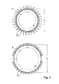
- FIG. 2 shows a perspective view of the guide rings
- FIG. 3 shows a first cable arrangement on the guide rings
- FIG. 4 shows a second cable arrangement on the guide rings
- FIG. 5 a )- c ) show a geometric illustration relating to cable twisting
- FIG. 6 shows strain relief for the cables
- FIG. 7 shows an enlarged partial view of the loop guide and length compensation device
- FIG. 8 shows another partial view with optional accessories.
- One exemplary embodiment of a wind energy installation according to the invention comprises a tower 10 with a nacelle 11 at its upper end. This is arranged such that it can swivel in the azimuth direction, by means of a motor or bearing, and has a rotatable wind rotor 12 on its end face. Via a drive shaft (not illustrated), it drives a generator 13 , which is arranged in the nacelle and has a converter 14 , converting the mechanical drive power of the wind rotor 12 to electrical power.
- a cable is arranged in the tower 10 , comprising a plurality of cables 21 , 22 for connection to the stator or rotor of the generator 13 (and possibly further signal cables 24 to an operating control system 17 for the wind energy installation), and a section 23 , which hangs downward in the tower 10 .
- the cables 21 , 22 are guided from the nacelle 11 into the tower 10 by means of a loop 20 and an opposing loop 30 .
- the loop guide 3 comprises an upper and a lower guide ring 31 , 32 , which are arranged one above the other coaxially, separated by about 3 m.
- the lower guide ring 32 is arranged in a rotationally fixed manner on a rocker 41 of the length compensation device 4 , to be precise via a journal bearing 43 , which acts on both sides and in which the individual bearing journals are diametrically opposite. This allows the lower guide ring to carry out a tilting movement, although it is secured against rotation about its center axis.
- the upper guide ring 31 is in contrast arranged loosely, that is to say it is attached only to the cables 21 , 22 . It can therefore freely follow the twisting of the cables as the nacelle 11 swivels, thus, from the rotational point of view, forming a loose bearing. This therefore allows the stretched area to be twisted.
- the rocker 41 is attached to the inside of the tower 10 via a swiveling bearing 42 .
- the rocker 41 can move up and down in the tower 10 , as a result of which the lower guide ring 32 , which is arranged at its free end, is moved to and fro with respect to the upper guide ring 31 . Because of this change in the separation between the two guide rings 31 , 32 , the size of the loop 20 which is formed by the cables 21 , 22 changes. Furthermore, a direction change 35 is provided, over which the opposing loop 30 is passed and from where it merges into the section 23 which hangs into the tower 10 .
- the direction change 35 holds the weight of the hanging section, and therefore keeps the loop together with the length compensation device 4 largely free of negative influences from the weight force of the hanging section.
- the direction change 35 can be provided with a coating 36 which increases the friction, or this can be ensured by attachment devices for providing adequately firm pressure on the cable harness 23 .
- the loop guide 3 and the length compensation device 4 are preferably arranged between two intermediate floors 16 , 16 ′. This ensures good access for maintenance. Because of the space-saving design according to the invention, an intermediate space with a height of about 5 m is sufficient even for tall wind energy installations with towers with a height of more than 70 m.
- FIG. 2 illustrates details relating to the upper and lower guide rings 31 , 32 . These have different diameters, with the upper having a diameter d 1 and the lower having a diameter d 2 . These comprise a multiplicity of radial holes, which are used as receptacles 34 for commercially available attachment devices for the individual cables 21 , 22 . The receptacles 34 are arranged at equal intervals on the respective ring, with a free space 33 for accommodation of the bearing journal 43 existing on the lower guide ring 32 .
- the separations between the receptacles 34 on the upper and lower guide rings 31 , 32 are matched to one another such that the angle separation ⁇ 1 on the upper guide ring 31 is equal to the angle separation ⁇ 2 on the lower guide ring 32 .
- the cables 21 to the rotor and the cables 22 to the stator are arranged grouped on the outer envelope surface of the upper and lower guide rings 31 , 32 ( FIG. 3 ). It is also possible for the cables 21 , 22 to be arranged on both sides, that is to say on the inner and outer envelope surfaces ( FIG. 4 ).
- FIG. 5 a illustrates the cable section which forms the loop 20 in the untwisted state, that is to say the nacelle 11 is in its normal position of 0° with respect to the tower 10 .
- the cable section which forms the loop has a length a of 7 m.
- the individual cables 21 , 22 are illustrated schematically via elongated lines in the cable section; in the untwisted state, they run parallel to the axis.
- FIG. 5 b illustrates the same cable section in the twisted state, to be precise for maximum permissible twisting of 1080°, corresponding to three complete revolutions in either direction.
- the individual cables 21 , 22 are now at an angle ⁇ , because of the twisting (the illustration in FIG. 5 b is schematic; the idealized position corresponds to that of an elongated “thread pitch” on a screw, with each cable 21 , 22 representing one screw thread).
- the relationship between the stretches and angles is illustrated in FIG. 5 c .
- the amount of space required at the side for the individual cables 21 , 22 is increased because of the angled position, to be precise being increased by the reciprocal of cos ⁇ .
- the length a is 7 m and the maximum twist is 1080°.
- the diameter of the (smaller) guide ring is 400 mm (circumference 1370 mm) and the diameter of the individual cables is 36 mm.
- the individual cable 21 , 22 has therefore been moved through a radial distance of 4.1 m when twisted to the maximum extent.
- Flexible strain relief is provided for the suspension of the individual cables 21 , 22 on the nacelle, in order to ensure that they are held securely and that they have adequate freedom of mobility.
- This flexible strain relief comprises a piece of mesh 51 , which is looped tightly around the individual cables 21 , 22 .
- the cable 21 , 22 is secured against sliding out, by means of the friction force. Because of the mesh structure, the mesh contracts as a result of the tension being exerted by the cable 21 , 22 , thus resulting in a self-securing effect. This therefore ensures that even large and heavy cables are held securely. In this case, the mesh retains its flexibility, as a result of which it has an adequate deformation capability to hold the cable even under the influence of the twisting.
- a cable eye 52 is provided for attachment at the upper end, and is attached to the nacelle 11 by means of a screw, hook or similar attachment element.
- FIG. 8 shows an overview of the loop guide 3 and the length compensation device 4 in the tower 10 .
- a number of options are additionally illustrated.
- a plurality of intermediate rings 37 are illustrated between the upper guide ring 31 and the lower guide ring 32 . These are arranged loosely, in the same manner as the upper guide ring 31 . While the upper guide ring 31 in general rotates with the nacelle 11 , the intermediate rings 37 rotate only partially therewith, with the extent to which they rotate therewith decreasing from top to bottom. The intermediate rings 37 ensure that the position of the cables 21 , 22 with respect to one another is maintained even in the case of relatively large loops.
- a counterweight 44 is illustrated for the length compensation device 4 . Its mass is designed to compensate for at least half of the weight force of the cable, taking account of the lever effect.
- the length compensation device 4 can therefore be operated largely freely of negative influences caused by the weight of the cables 21 , 22 .
- active compensation can be provided (illustrated by dashed lines).
- This comprises a control device 45 which uses a signal originating from the operating control system 17 relating to the twist angle to determine the effective shortened cable length b, and correspondingly adjusts the rocker 41 via an actuator 46 , in order to compensate for the shortening A.
Landscapes
- Engineering & Computer Science (AREA)
- Life Sciences & Earth Sciences (AREA)
- Sustainable Development (AREA)
- Sustainable Energy (AREA)
- Chemical & Material Sciences (AREA)
- Combustion & Propulsion (AREA)
- Mechanical Engineering (AREA)
- General Engineering & Computer Science (AREA)
- Wind Motors (AREA)
- Bridges Or Land Bridges (AREA)
Applications Claiming Priority (4)
| Application Number | Priority Date | Filing Date | Title |
|---|---|---|---|
| DE102009013728A DE102009013728A1 (de) | 2009-03-20 | 2009-03-20 | Windenergieanlage mit verdrillbarer Gondel-Kabelführung |
| DE102009013728.9 | 2009-03-20 | ||
| DE102009013728 | 2009-03-20 | ||
| PCT/EP2010/001789 WO2010105852A2 (de) | 2009-03-20 | 2010-03-22 | Windenergieanlage mit verdrillbarer gondel-kabelführung |
Publications (2)
| Publication Number | Publication Date |
|---|---|
| US20120006578A1 US20120006578A1 (en) | 2012-01-12 |
| US9190823B2 true US9190823B2 (en) | 2015-11-17 |
Family
ID=42663912
Family Applications (1)
| Application Number | Title | Priority Date | Filing Date |
|---|---|---|---|
| US13/257,857 Active 2032-11-05 US9190823B2 (en) | 2009-03-20 | 2010-03-22 | Wind energy plant having a twistable nacelle cable guide |
Country Status (6)
| Country | Link |
|---|---|
| US (1) | US9190823B2 (de) |
| EP (1) | EP2409031B1 (de) |
| DE (1) | DE102009013728A1 (de) |
| DK (1) | DK2409031T3 (de) |
| ES (1) | ES2435251T3 (de) |
| WO (1) | WO2010105852A2 (de) |
Cited By (2)
| Publication number | Priority date | Publication date | Assignee | Title |
|---|---|---|---|---|
| US10047727B2 (en) | 2013-07-30 | 2018-08-14 | Wobben Properties Gmbh | Wind turbine comprising a transport unit |
| US11415114B2 (en) * | 2017-11-15 | 2022-08-16 | Siemens Gamesa Renewable Energy A/S | Offshore structure and method for attaching a tube or cable to an appliance of an offshore structure |
Families Citing this family (15)
| Publication number | Priority date | Publication date | Assignee | Title |
|---|---|---|---|---|
| US9022739B2 (en) * | 2011-02-07 | 2015-05-05 | Vestas Wind Systems A/S | Wind turbine generator with a lifting device |
| EP2505832B1 (de) * | 2011-03-30 | 2018-08-08 | Vestas Wind Systems A/S | Windturbinenanordnung |
| DK177337B1 (en) | 2011-10-26 | 2013-01-21 | Envision Energy Denmark Aps | Wind Turbine Including a Cable Loop |
| FR2987467B1 (fr) * | 2012-02-27 | 2016-12-09 | Somfy Sas | Procedes de commande et de parametrage d’une installation domotique et installation domotique mettant en œuvre ces procedes |
| US10678279B2 (en) * | 2012-08-01 | 2020-06-09 | Tendril Oe, Llc | Optimization of energy use through model-based simulations |
| DE102012113058A1 (de) * | 2012-12-21 | 2014-06-26 | 2-B Energy B.V. | Verfahren und Vorrichtung zur Ermittlung und/oder Beseitigung der Verdrillung eines Kabelbaumes einer Windenergieanlage |
| DE102013210969A1 (de) * | 2013-06-12 | 2014-12-18 | Siemens Aktiengesellschaft | Elektrische Kupplung |
| DE102013011952A1 (de) | 2013-07-18 | 2015-01-22 | Ssb Wind Systems Gmbh & Co. Kg | Rotor einer Windkraftanlage |
| US9831653B2 (en) * | 2015-05-19 | 2017-11-28 | Ge Energy Power Conversion Technology Ltd | Cable twist allowance system for power system |
| DE202017105194U1 (de) * | 2017-07-27 | 2017-09-05 | Hans Benkert | Kabelstrumpf, insbesondere für Windkraftanlagen |
| DE102017008893A1 (de) | 2017-09-22 | 2019-03-28 | Senvion Gmbh | Kabelsattel zum Stützen von Kabeln in einer Kabelschlaufe einer Windkraftanlage |
| DE102019115861A1 (de) * | 2019-06-11 | 2020-12-17 | Nordex Energy Gmbh | Vorrichtung zur elektromagnetischen Abschirmung in einem Turm einer Windenergieanlage |
| EP4119793B1 (de) * | 2021-07-15 | 2026-01-21 | General Electric Renovables España S.L. | Kabelführungsstruktur für einen turm einer windturbine, verfahren zur montage einer kabelführungsstruktur und windturbine |
| CN115706398B (zh) * | 2021-08-13 | 2025-04-08 | 中国三峡建工(集团)有限公司 | 风力发电机组及其偏航扭缆结构 |
| EP4234925A1 (de) * | 2022-02-24 | 2023-08-30 | Siemens Gamesa Renewable Energy A/S | Windturbine und verfahren zum herstellen einer windturbine |
Citations (6)
| Publication number | Priority date | Publication date | Assignee | Title |
|---|---|---|---|---|
| US4070083A (en) * | 1977-01-31 | 1978-01-24 | Dipalma Joseph | Electrical power line extension |
| WO2000036724A2 (en) | 1998-12-17 | 2000-06-22 | Dan-Control Engineering A/S | Wind mill with a suspension for cables and the like, such suspension for cables and the like and a holder for such suspension |
| DE20116756U1 (de) | 2001-10-16 | 2002-01-24 | Brehm, Bernhardt, 75365 Calw | Dreh-Durchführung zur Stromübertragung |
| JP2005137097A (ja) | 2003-10-29 | 2005-05-26 | Ryokeiso Kk | ケーブル設置装置及び方法 |
| EP1921311A1 (de) | 2006-11-09 | 2008-05-14 | Winwind Oy | Windkraftanlage |
| JP2008298051A (ja) | 2007-06-04 | 2008-12-11 | Ebara Corp | 風力発電装置 |
Family Cites Families (1)
| Publication number | Priority date | Publication date | Assignee | Title |
|---|---|---|---|---|
| US6786306B2 (en) * | 2002-04-17 | 2004-09-07 | James L. Tiner | Elevator mechanism |
-
2009
- 2009-03-20 DE DE102009013728A patent/DE102009013728A1/de not_active Withdrawn
-
2010
- 2010-03-22 WO PCT/EP2010/001789 patent/WO2010105852A2/de not_active Ceased
- 2010-03-22 US US13/257,857 patent/US9190823B2/en active Active
- 2010-03-22 ES ES10710552T patent/ES2435251T3/es active Active
- 2010-03-22 EP EP10710552.0A patent/EP2409031B1/de active Active
- 2010-03-22 DK DK10710552.0T patent/DK2409031T3/da active
Patent Citations (6)
| Publication number | Priority date | Publication date | Assignee | Title |
|---|---|---|---|---|
| US4070083A (en) * | 1977-01-31 | 1978-01-24 | Dipalma Joseph | Electrical power line extension |
| WO2000036724A2 (en) | 1998-12-17 | 2000-06-22 | Dan-Control Engineering A/S | Wind mill with a suspension for cables and the like, such suspension for cables and the like and a holder for such suspension |
| DE20116756U1 (de) | 2001-10-16 | 2002-01-24 | Brehm, Bernhardt, 75365 Calw | Dreh-Durchführung zur Stromübertragung |
| JP2005137097A (ja) | 2003-10-29 | 2005-05-26 | Ryokeiso Kk | ケーブル設置装置及び方法 |
| EP1921311A1 (de) | 2006-11-09 | 2008-05-14 | Winwind Oy | Windkraftanlage |
| JP2008298051A (ja) | 2007-06-04 | 2008-12-11 | Ebara Corp | 風力発電装置 |
Non-Patent Citations (1)
| Title |
|---|
| International Search Report and Written Opinion mailed Nov. 30, 2010, directed to International Application No. PCT/EP2010/001789; 8 pages. |
Cited By (2)
| Publication number | Priority date | Publication date | Assignee | Title |
|---|---|---|---|---|
| US10047727B2 (en) | 2013-07-30 | 2018-08-14 | Wobben Properties Gmbh | Wind turbine comprising a transport unit |
| US11415114B2 (en) * | 2017-11-15 | 2022-08-16 | Siemens Gamesa Renewable Energy A/S | Offshore structure and method for attaching a tube or cable to an appliance of an offshore structure |
Also Published As
| Publication number | Publication date |
|---|---|
| EP2409031B1 (de) | 2013-08-28 |
| DE102009013728A1 (de) | 2010-09-30 |
| EP2409031A2 (de) | 2012-01-25 |
| ES2435251T3 (es) | 2013-12-17 |
| WO2010105852A3 (de) | 2011-02-24 |
| DK2409031T3 (da) | 2013-12-02 |
| US20120006578A1 (en) | 2012-01-12 |
| WO2010105852A2 (de) | 2010-09-23 |
Similar Documents
| Publication | Publication Date | Title |
|---|---|---|
| US20120006578A1 (en) | Wind energy plant having a twistable nacelle cable guide | |
| CN103114973B (zh) | 含有电缆环的风力涡轮机 | |
| US4217501A (en) | Mounting for windmills | |
| US9051920B2 (en) | Development of a new tower cabling | |
| CN102265030B (zh) | 风力发电装置及使用于该装置的电缆支承结构 | |
| US20150260166A1 (en) | Cable support arrangement | |
| US10625993B2 (en) | Crane of a wind turbine | |
| AU2011260249A1 (en) | Tower for a wind turbine | |
| JP2008298051A (ja) | 風力発電装置 | |
| US11603293B2 (en) | Assembly for rotating a suspended load | |
| CN103850888A (zh) | 风力涡轮机塔架中的电缆扭转系统 | |
| WO2009061209A1 (en) | Wind turbine with electrical swivel | |
| US11453576B2 (en) | System, device and method for lifting and controlling the horizontal orientation and/or position of components | |
| EP4077935B1 (de) | Selbstklemmender kabelschutz zum klemmen von stromkabeln eines stromkabelbündels einer kabelhalteranordnung in einer windturbine, kabelhalter und windturbine | |
| EP2478215B1 (de) | Übertragungs- und führungssystem mit knickschutz für kabel | |
| AU2014298724A1 (en) | Wind turbine | |
| US9845785B2 (en) | Connection systems | |
| EP3322893B1 (de) | Kabelführung für windturbinensystem mit mehreren rotoren | |
| CN107850038B (zh) | 用于具有多个转子的风轮机系统的线缆布设 | |
| CN203932295U (zh) | 一种直筒式电缆卷绕装置 | |
| JP2000274347A (ja) | 風力発電装置 | |
| JP2011214422A (ja) | 風力発電装置 | |
| DK201770976A1 (en) | LIFTING AND CONTROLLING THE HORIZONTAL ORIENTATION OF COMPONENTS |
Legal Events
| Date | Code | Title | Description |
|---|---|---|---|
| AS | Assignment |
Owner name: REPOWER SYSTEMS SE, GERMANY Free format text: ASSIGNMENT OF ASSIGNORS INTEREST;ASSIGNOR:SCHUBERT, MATTHIAS;REEL/FRAME:027523/0864 Effective date: 20111130 |
|
| AS | Assignment |
Owner name: REPOWER SYSTEMS SE, GERMANY Free format text: CHANGE OF NAME;ASSIGNOR:REPOWER SYSTEMS AG;REEL/FRAME:034786/0585 Effective date: 20101025 |
|
| AS | Assignment |
Owner name: SENVION SE, GERMANY Free format text: CHANGE OF NAME;ASSIGNOR:REPOWER SYSTEMS SE;REEL/FRAME:034806/0074 Effective date: 20140120 |
|
| STCF | Information on status: patent grant |
Free format text: PATENTED CASE |
|
| FEPP | Fee payment procedure |
Free format text: SURCHARGE FOR LATE PAYMENT, LARGE ENTITY (ORIGINAL EVENT CODE: M1554); ENTITY STATUS OF PATENT OWNER: LARGE ENTITY |
|
| MAFP | Maintenance fee payment |
Free format text: PAYMENT OF MAINTENANCE FEE, 4TH YEAR, LARGE ENTITY (ORIGINAL EVENT CODE: M1551); ENTITY STATUS OF PATENT OWNER: LARGE ENTITY Year of fee payment: 4 |
|
| MAFP | Maintenance fee payment |
Free format text: PAYMENT OF MAINTENANCE FEE, 8TH YEAR, LARGE ENTITY (ORIGINAL EVENT CODE: M1552); ENTITY STATUS OF PATENT OWNER: LARGE ENTITY Year of fee payment: 8 |
|
| AS | Assignment |
Owner name: SENVION AG, GERMANY Free format text: CHANGE OF NAME;ASSIGNOR:SENVION SE;REEL/FRAME:069849/0638 Effective date: 20150622 |
|
| AS | Assignment |
Owner name: SENVION GMBH, GERMANY Free format text: CHANGE OF NAME;ASSIGNOR:SENVION AG;REEL/FRAME:069924/0352 Effective date: 20150626 |
|
| AS | Assignment |
Owner name: SENVION DEUTSCHLAND GMBH, GERMANY Free format text: CHANGE OF NAME;ASSIGNOR:SENVION GMBH;REEL/FRAME:069986/0450 Effective date: 20190911 |
|
| AS | Assignment |
Owner name: SIEMENS GAMESA RENEWABLE ENERGY SERVICE GMBH, GERMANY Free format text: CHANGE OF NAME;ASSIGNOR:SENVION DEUTSCHLAND GMBH;REEL/FRAME:070031/0577 Effective date: 20200624 |
|
| AS | Assignment |
Owner name: SIEMENS GAMESA RENEWABLE ENERGY SERVICE GMBH, GERMANY Free format text: REQUEST FOR ASSIGNEE ADDRESS CHANGE;ASSIGNOR:SIEMENS GAMESA RENEWABLE ENERGY SERVICE GMBH;REEL/FRAME:072597/0865 Effective date: 20230831 |