US916590A - Amusement apparatus. - Google Patents
Amusement apparatus. Download PDFInfo
- Publication number
- US916590A US916590A US42135408A US1908421354A US916590A US 916590 A US916590 A US 916590A US 42135408 A US42135408 A US 42135408A US 1908421354 A US1908421354 A US 1908421354A US 916590 A US916590 A US 916590A
- Authority
- US
- United States
- Prior art keywords
- truck
- horse
- wheel
- amusement apparatus
- frame
- Prior art date
- Legal status (The legal status is an assumption and is not a legal conclusion. Google has not performed a legal analysis and makes no representation as to the accuracy of the status listed.)
- Expired - Lifetime
Links
- 230000008933 bodily movement Effects 0.000 description 7
- 230000033001 locomotion Effects 0.000 description 6
- 241000283086 Equidae Species 0.000 description 4
- 238000010276 construction Methods 0.000 description 2
- 230000000881 depressing effect Effects 0.000 description 2
- 230000032683 aging Effects 0.000 description 1
- 238000010586 diagram Methods 0.000 description 1
- 230000000630 rising effect Effects 0.000 description 1
Images
Classifications
-
- A—HUMAN NECESSITIES
- A63—SPORTS; GAMES; AMUSEMENTS
- A63H—TOYS, e.g. TOPS, DOLLS, HOOPS OR BUILDING BLOCKS
- A63H18/00—Highways or trackways for toys; Propulsion by special interaction between vehicle and track
- A63H18/12—Electric current supply to toy vehicles through the track
Definitions
- the horse is mounted on a rocking bar or frame, mounted on cranks connected to or supported by leading andtrailing wheels, adapted to run on a mono-rail preferably laid below the surface of the ground in the bottom of a groove and guided in a suitable manner.
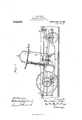
- Figure 1 is a side elevation of the trolley or running gear on which the mechanical horse is mounted
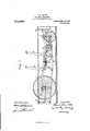
- Fig. 2 is a-similar View to Fig. 1, showing a slightly modified form of gear
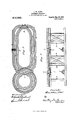
- Fig. 3 is a diagram of the track or railway on which the horses are intended to run
- Fig. 4 is a transverse section on a larger scale through the track conduits.
- the horse which is only partly shown at a is mounted on a frame I) supported between a track wheel 0 of comparatively large diameter, and a smaller wheel (Z.
- the smaller wheel d supports a frame or bracket 6 on which a crank shaft f is mounted to rotate, while the large wheel has a crank axle g fixed therein, so as to be driven by the wheel 0.
- the supporting frame I) is constructed of two longitudinal side members with distance pieces between them and the ends of the side members are connected to the cranks of the shaft f and axle g in such a manner that as the wheels travel along the track the connecting bar or frame I) has a rocking motion imparted to it being actuated from the axle of the leadingtrack wheel.
- the frame I) and. the smaller wheel are inclosed in the groove or conduit hereinafter described in which the track is laid.
- the saddle is connected with the large track wheel 0 through a plunger frame 'i, crank lever j, connecting link is and fork Z which is pivotally supported on the axle g and carries on each arm a pawl m engaging with a ratchet n on the hub of the wheel 0.
- the lever j is fulcrumed on a frame Q suspended between the track wheels and carries grooved rollers T which couple the lever to the lower bar i of the plunger frame i enabling the vertical component of the movement of the plunger frame produced by the rider depressing the saddle to be fully utilized for assisting the propulsion.
- Springs 0 located in the tubes h bear against the collars 0 on the lunger frame i and raise the saddle after grav depression.
- a guide wheel p is mounted on the frame I) which supports the horse and bears against the sides of the groove at the top of the conduit to keep the horse upright.
- Guide wheels 29 p are also arranged at the front and rear ends of the trolley.
- the track with which my invention is used is preferably laid in the form shown in plan in Fig. 3 in which each line represents a conduit. By this arrangement the distances to be traversed by each horse covering the complete course are approximately equal. If A be the starting platform the course taken by each horse from start to finish is indicated by shown in Fig. 2 the pawl and ratchet mechthe arrows. Bridges are constructed at the points of intersection of the tracks 0.
- conduit for the rail i may be adopted. As shown in 4 the conduit is fitted with rails it through which current is supplied from any suitable source to the motor a.
- A11 amusement apparatus comprising in combination, a single track truck provided with wheels, a horse supporting frame mounted on and oscillated by said truck, and means operated solely by movement of the rider for propelling sain truck,
- An amusement apparatus comprising in combination, a trur Y provided with wheels, a horse supporting irammounted on and oscillated by said truck, and means operated solely by movement of the rider for propelling said truck.
- An amusement apparatus comprising in combination, a single track truck provided with wheels, a horse supporting frame mounted on said truck, and means operated solely by bodily movement of the rider for propelling said truck.
- An amusement apparatus comprising in combination, a single track truck provided with wheels, means for maintaining said truck in an upright position, a horse supporting framemounted on and operated by said truck, and means operated solely by bodily movement of the rider for propelling said truck at different rates of speed.
- An amusement apparatus comprising in combination, a single track truck provided with wheels, a horse supporting frame mounted on and oscillated by said truck, and means adapted for connection with a horse saddle for propelling said truck solely by bodily movement of the rider,
- An amusement apparatus comprising in combination, a single track truck provided with wheels, a horse supporting frame mounted on and oscillated by said truck, and yieldingly acting means adapted for connection With the saddle of the horse and operated solely by bodily movement of the rider for propelling said truck '7.
- An amusement apparatus comprising in combination, a single track truck provided ith a driving and trailer wheel, a horse supporting frame movably mounted on said truck and oscillated by said driving wheel, and means connected with said driving wheel and operated solely by bodily movement of the rider fol-propelling said truck.
- An amusement apparatus comprising in combination, a single track truck provided with a driving and a trailer wheel, a centrally disposed frame supporting member for said truck, a crank for one end of said truck and a crank connected with said driving wheel, a horse supporting frame movably mounted on said member and connected with said crank, and means including a ball and ratchet wheel operated solely by bodily movement of the rider for propelling the truck.
- An amusement apparatus comprising in combination, a single track truck provided with a propelling and a trailing wheel, an axle for said propelling wheel provided with a crank and a ratchet Wheel, an idler crank for said truck, a centrally disposed supporting member for said truck, means for maintaining said truck in an upright position, a horse supporting frame provided with a roller movable on said member, said framebeing connected with said idler crank and axle crank and oscillated by the latter, a hollow support extending upwardly from said frame for supporting the horse, a pawl device op erativeiy en aging said ratchet wheel, means extending through said support and adapted for connection with the saddle for operation by bodily movement of the rider, and a roller connection between said means and said. pawl device substantially as described.
Landscapes
- Motorcycle And Bicycle Frame (AREA)
Description
T. W. POTTS.
AMUSEMENT APPARATUS.
APPLICATION FILED MAR. 16, 190B.
Patented Mar. 30, 1909.
3 SHEETS-SHEET 1.
Inz/nZU r.
rul- NORRIS Pnmu m, wAsHmawM-D. t
T. W. POTTS.
AMUSEMENT APPARATUS.
APPLIOATION I'ILED MAR-16, 190a.
' 916,590. Patented Mar. 30, 1909.
3 SHEETS-SHEET 2.
may:
1n: nonlus rlruu cm, \uanmmon, b. c.
T. W. POTTS.
AMUSEMENT APPARATUS.
APPLIOATION PILBDMAR. 10, 1909.
Patented Mar. 30, 1909.-
8 SHEETS-SHEET B.
QV W101i Irzuenfin 161%"??? e ss e s, I
1n: NoRRIs PETERS ca, wAsnmnroN, c. c.
THOMAS WILLIAM POTTS, OF LONDON, ENGLAND.
AMUSEMENT APPARATUS.
Specification of Letters Patent.
Patented March 30, 1909.
Application filed March 16, 1908. Serial No. 421,35
To all whom it may concern:
Be it known that I, THOMAS VVILLIAM Po'rrs, asubject of the King of Great Britain and Ireland, residing at 30 Chesilton road, Fulham, London, England, have invented certain new and useful Improvements in Amusement Apparatus; and I do hereby declare the following to be a full, clear, and exact description of the invention, such as will enable others skilled in the art to which it appertainsto make and use the same.
This invention for improvements in velocipede or similar horses for recreation or amusementrelates to horses of the type in which the horse is connected to the wheels in such a manner that a rising and falling motion is imparted to the horse, and the speed may be accelerated by the movement of the rider, and has for its object to enable such horses to travel on a single rail track.
According to this invention the horse is mounted on a rocking bar or frame, mounted on cranks connected to or supported by leading andtrailing wheels, adapted to run on a mono-rail preferably laid below the surface of the ground in the bottom of a groove and guided in a suitable manner.
In the accompanying drawings Figure 1 is a side elevation of the trolley or running gear on which the mechanical horse is mounted, Fig. 2 is a-similar View to Fig. 1, showing a slightly modified form of gear, Fig. 3 is a diagram of the track or railway on which the horses are intended to run, and Fig. 4 is a transverse section on a larger scale through the track conduits.
The horse which is only partly shown at a is mounted on a frame I) supported between a track wheel 0 of comparatively large diameter, and a smaller wheel (Z. The smaller wheel d supports a frame or bracket 6 on which a crank shaft f is mounted to rotate, while the large wheel has a crank axle g fixed therein, so as to be driven by the wheel 0.
The supporting frame I) is constructed of two longitudinal side members with distance pieces between them and the ends of the side members are connected to the cranks of the shaft f and axle g in such a manner that as the wheels travel along the track the connecting bar or frame I) has a rocking motion imparted to it being actuated from the axle of the leadingtrack wheel. The frame I) and. the smaller wheel are inclosed in the groove or conduit hereinafter described in which the track is laid.
Above the surface of the ground but as near thereto as possible I support the horse by means of pillars or tubes it fixed at their upper ends in the body a of the horse, and at their lower ends which pass into the track groove, to the rocking bar I).
In order that the rider may assist in propelling the horse the saddle is connected with the large track wheel 0 through a plunger frame 'i, crank lever j, connecting link is and fork Z which is pivotally supported on the axle g and carries on each arm a pawl m engaging with a ratchet n on the hub of the wheel 0. The lever j is fulcrumed on a frame Q suspended between the track wheels and carries grooved rollers T which couple the lever to the lower bar i of the plunger frame i enabling the vertical component of the movement of the plunger frame produced by the rider depressing the saddle to be fully utilized for assisting the propulsion. Springs 0 located in the tubes h bear against the collars 0 on the lunger frame i and raise the saddle after caci depression.
A guide wheel p is mounted on the frame I) which supports the horse and bears against the sides of the groove at the top of the conduit to keep the horse upright. Guide wheels 29 p are also arranged at the front and rear ends of the trolley.
In the modified form of construction anism is replaced by an electric motor 8 in which the speed is adapted to be varied by introducing more or less of a resistance or by altering the reluctance of the field magnet system. The speed varying device of whatever type, is operatively connected with the lever j which corresponds to the lever in Fig. 1 and is similarly actuated by depressing the saddle. Thus the rider by his own exertions can accelerate the speed and mechanical horse racing is made possible.
The track with which my invention is used is preferably laid in the form shown in plan in Fig. 3 in which each line represents a conduit. By this arrangement the distances to be traversed by each horse covering the complete course are approximately equal. If A be the starting platform the course taken by each horse from start to finish is indicated by shown in Fig. 2 the pawl and ratchet mechthe arrows. Bridges are constructed at the points of intersection of the tracks 0.
Any suitable construction of conduit for the rail i may be adopted. As shown in 4 the conduit is fitted with rails it through which current is supplied from any suitable source to the motor a.
l Vhat I claim as my invention and desire to secure by Letters Patent is 1. A11 amusement apparatus comprising in combination, a single track truck provided with wheels, a horse supporting frame mounted on and oscillated by said truck, and means operated solely by movement of the rider for propelling sain truck,
2. An amusement apparatus comprising in combination, a trur Y provided with wheels, a horse supporting irammounted on and oscillated by said truck, and means operated solely by movement of the rider for propelling said truck.
3. An amusement apparatus comprising in combination, a single track truck provided with wheels, a horse supporting frame mounted on said truck, and means operated solely by bodily movement of the rider for propelling said truck.
4. An amusement apparatus comprising in combination, a single track truck provided with wheels, means for maintaining said truck in an upright position, a horse supporting framemounted on and operated by said truck, and means operated solely by bodily movement of the rider for propelling said truck at different rates of speed.
5. An amusement apparatus comprising in combination, a single track truck provided with wheels, a horse supporting frame mounted on and oscillated by said truck, and means adapted for connection with a horse saddle for propelling said truck solely by bodily movement of the rider,
6. An amusement apparatus comprising in combination, a single track truck provided with wheels, a horse supporting frame mounted on and oscillated by said truck, and yieldingly acting means adapted for connection With the saddle of the horse and operated solely by bodily movement of the rider for propelling said truck '7. An amusement apparatus comprising in combination, a single track truck provided ith a driving and trailer wheel, a horse supporting frame movably mounted on said truck and oscillated by said driving wheel, and means connected with said driving wheel and operated solely by bodily movement of the rider fol-propelling said truck.
8. An amusement apparatus comprising in combination, a single track truck provided with a driving and a trailer wheel, a centrally disposed frame supporting member for said truck, a crank for one end of said truck and a crank connected with said driving wheel, a horse supporting frame movably mounted on said member and connected with said crank, and means including a ball and ratchet wheel operated solely by bodily movement of the rider for propelling the truck.
9. An amusement apparatus comprising in combination, a single track truck provided with a propelling and a trailing wheel, an axle for said propelling wheel provided with a crank and a ratchet Wheel, an idler crank for said truck, a centrally disposed supporting member for said truck, means for maintaining said truck in an upright position, a horse supporting frame provided with a roller movable on said member, said framebeing connected with said idler crank and axle crank and oscillated by the latter, a hollow support extending upwardly from said frame for supporting the horse, a pawl device op erativeiy en aging said ratchet wheel, means extending through said support and adapted for connection with the saddle for operation by bodily movement of the rider, and a roller connection between said means and said. pawl device substantially as described.
In testimony whereof I have affixed my signature, in presence of two Witnesses.
THOMAS W'ILLIAM POTTS. lVitnesses:
JOHN W. MAcKENzIE, ALBERT JoNEs.
Priority Applications (1)
| Application Number | Priority Date | Filing Date | Title |
|---|---|---|---|
| US42135408A US916590A (en) | 1908-03-16 | 1908-03-16 | Amusement apparatus. |
Applications Claiming Priority (1)
| Application Number | Priority Date | Filing Date | Title |
|---|---|---|---|
| US42135408A US916590A (en) | 1908-03-16 | 1908-03-16 | Amusement apparatus. |
Publications (1)
| Publication Number | Publication Date |
|---|---|
| US916590A true US916590A (en) | 1909-03-30 |
Family
ID=2985025
Family Applications (1)
| Application Number | Title | Priority Date | Filing Date |
|---|---|---|---|
| US42135408A Expired - Lifetime US916590A (en) | 1908-03-16 | 1908-03-16 | Amusement apparatus. |
Country Status (1)
| Country | Link |
|---|---|
| US (1) | US916590A (en) |
-
1908
- 1908-03-16 US US42135408A patent/US916590A/en not_active Expired - Lifetime
Similar Documents
| Publication | Publication Date | Title |
|---|---|---|
| US858624A (en) | Pleasure-railway. | |
| US916590A (en) | Amusement apparatus. | |
| US583109A (en) | Daniels | |
| US958160A (en) | Gravity-automobile. | |
| US511862A (en) | Electric locomotive for elevated tracks | |
| US1462560A (en) | Mechanical racing course | |
| US566926A (en) | Bicycle-railway | |
| US1527893A (en) | Pleasure railway | |
| US526984A (en) | Mechanically-propelled figure | |
| US1632092A (en) | Velocipede | |
| US551814A (en) | Man-motor | |
| US259411A (en) | Velocipede | |
| US1370385A (en) | Amusement device | |
| US886627A (en) | Amusement device. | |
| US455288A (en) | Apparatus for producing illusory dramatic effects | |
| US689599A (en) | Velocipede. | |
| US125224A (en) | Improvement in propelling street-cars | |
| US832459A (en) | Merry-go-round. | |
| US645579A (en) | Velocipede. | |
| US868564A (en) | Mechanical animal. | |
| US1379604A (en) | Velocipede | |
| US207240A (en) | Improvement in velocipedes | |
| US488200A (en) | Elevated railway | |
| US399997A (en) | Elevated railway | |
| US1561538A (en) | Velocipede |