US583109A - Daniels - Google Patents
Daniels Download PDFInfo
- Publication number
- US583109A US583109A US583109DA US583109A US 583109 A US583109 A US 583109A US 583109D A US583109D A US 583109DA US 583109 A US583109 A US 583109A
- Authority
- US
- United States
- Prior art keywords
- horse
- truck
- rider
- wheel
- daniels
- Prior art date
- Legal status (The legal status is an assumption and is not a legal conclusion. Google has not performed a legal analysis and makes no representation as to the accuracy of the status listed.)
- Expired - Lifetime
Links
- 241000283086 Equidae Species 0.000 description 14
- 230000036633 rest Effects 0.000 description 8
- 241000777300 Congiopodidae Species 0.000 description 4
- 210000003128 Head Anatomy 0.000 description 2
- 101700078171 KNTC1 Proteins 0.000 description 2
- 230000001276 controlling effect Effects 0.000 description 2
- 230000003292 diminished Effects 0.000 description 2
- 230000005611 electricity Effects 0.000 description 2
- 150000002500 ions Chemical class 0.000 description 2
- JVTAAEKCZFNVCJ-UHFFFAOYSA-N lactic acid Chemical compound CC(O)C(O)=O JVTAAEKCZFNVCJ-UHFFFAOYSA-N 0.000 description 2
- 230000001105 regulatory Effects 0.000 description 2
Images


Classifications
-
- A—HUMAN NECESSITIES
- A63—SPORTS; GAMES; AMUSEMENTS
- A63G—MERRY-GO-ROUNDS; SWINGS; ROCKING-HORSES; CHUTES; SWITCHBACKS; SIMILAR DEVICES FOR PUBLIC AMUSEMENT
- A63G19/00—Toy animals for riding
- A63G19/20—Toy animals for riding motor-driven
Definitions
- My invention relates to improvements in carousels or merry go-rounds for racing purposes, in which the horse or other figure is under control of the rider as to speed and stopping and starting; and the objects of myimprovements are, first, to provide an electrical motor for operating all of the horses simultaneously from a single battery; second, to provide an independent motor mechanism for each horse, and, third, to provide means for enabling the rider of each horse to control the starting, stopping, and speed of the horse.
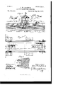
- Figure 1 is a side elevation of a horse and a sectional view of the truck on lines 0 D of Fig. 3.
- Fig. 2 is a front representation of the horse and a sectional view of the truck on lines B B of Fig.
- Fig. 3 is a top plan view of the truck with the horse removed; and Fig. 4 is a view of the horses head, partly broken away, showing the mechanism for controlling the flow of electricity to the motor mechanism.
- Fig. 5 is a perspective view of the apparatus, showing the slotted platform and the figures with their riders mounted thereon.
- This apparatus consists of the ordinary slotted platform, builtin circular or elliptical form, underneath which are trucks mounted upon railway-tracks in the usual manner.
- the wooden horses are supported on rods 1) and c and are connected in front to an adj ustable gear-crank d and receiving an up-anddown motion therefrom when the tru ck is in motion.
- the back rod 0 rests rigidly on the truck. -The body of the horse rests on the upper end of said rods on hinged brackets c and f.
- the rod 0 is rectangular in cross-see tion and is provided on the top bya hinge f, the upper part of which is attached to the body of the horse, which keeps said horse from lateral motion.
- the rest 9 of the spring his rigidly fixed to the rod 0 by set-screws and supports the coil-spring h, which receives part of the energy of the riders body while in motion on the horses back.
- the lower part of the rod 0 rests on a rigid support i neXt to the top of the truck and has at a certain distance above the platform-slot a roller is, freely revolving between two guards near the slot, thus keeping the rod in vertical position.
- the electric current is fed through one rail, while the other serves to complete the circuit, the positive current enteringthe wheel 19 and axle q, which is insulated from the wheel Z, and through sliding contact .9 on axle enters the cornmutatonbrushes and armature of the motor when the connection is made.
- the mechanism for m akin g and breaking the circuit is shown in Fig. at and rests inside the horses mouth. It is controlled by the riderby pulling on the reins, (clearly shown in said figure,) which are attached to segments a and r, said segments being connected by suitable wires to the electric mechanism. They are normally kept separate by insulated coiled springs, as shown in the drawings.
- a gear-wheel d In the front part of the truck a gear-wheel d is mounted,which meshes with a pinion 2, which vis rigidly attached to the front axle.
- Said gear-Wheel has a wrist-pin m attached near its periphery, upon which is mounted the rod 1), which supports the front part of the horse, by means of a jointed bracket 6.
- the range of up-and-down movement of the horse is regulated by moving the wrist-pin m up or down in the slot at of gear-wheel d.
- the truck receives its primary motion from the electric motor on the rear axle; but by the mechanism just described the motion can be accelerated and the speed increased by action of the rider of the horse.
- By applying skilfully his own weight increases the momentum and enables one rider to get ahead of the others of his racing companions just in proportion to his skill and strength in manipulating the device.
- Another element which increases or diminishes the speed resides in the mechanism in the horses mouth for making and breaking the circuit, which may be increased or diminished at the will of the rider within certain limits by making the connection more or less complete.
- Another resultant object of this mechanism is to enable the rider to stop or start his horse at will by having under his control the circuit-breaking mechanismpulling on the reins making the connection and slacking the reins breaking it, as is obvious from the drawings.
- the four-wheel truck can be superseded by a two-wheel truck built 011 the bicycle system running on one rail only, which is the eurrent-feederto the motorplaccd 011 the back wheel, and the back current can be conducted through the roller 7,: and one of the slot guardrails '2.
- the current is to be supplied from a central station and may be of variable voltage, from seventy-five volts up, not exceeding two hundred volts, carried by carefullyinsulated wires to the switch a and r in Fig. 4.
- the motor may be either a reduction-gear motor or a direct axle motor.
- I11 a carousel a series of horses or other figures adapted for riding and mounted upon suitable mechanisms carrying independent motors said motors deriving their power from a common source and each provided with auxiliary propelling mechanism for increasing its speed at the will of the rider independently of the other mechanisms in the series, substantially as set forth.
- the truck having the standard 0 with the horse or other figu re adapted to be used as a seat for a rider pivot-ally mounted upon said standard, in combination with the standard I) pivotally attached to the forward end of said figure and connected by its lower end to a crank-pin mounted upon a gear-wheel for connecting said gear-wheel to the axle of the truck and provided with mechanism to enable the rider to increase or decrease the speed of the truck independent of the primary moving meehan ism ,substantially as described.
Description
(No Model.) 3 Sheets-Sheet 1.
J. W. DANIELS;
ELECTRIC RAGE HORSE GAROUSEL. No. 583,109. Patented May 25,1897.
L I in uh:
WW! I (N0 Mode l.) 3 SheetsSheet 2. J. W. DANIELS. ELECTRIC RAGE HORSE CAROUSEL.
No. 583,109. Patented Ma 25,1897.
(No Model.) I a Sheets-Sheet a.
J. W. DANIELS. ELECTRIC RACE HORSE ,CAROUSEL.
No. 583,109. Patented May 25,1897.
,LM!iiiHlf hiH lHIHIHIIIIHHIIIII lllllllllll F593 (H ii ii Fries.
ATENT JAMES \VASHINGTON DANIELS, OF PATERSON, NE" JERSEY.
ELECTRIC RACE-HORSE CAROUSEL.
SPECIFICATION forming part of Letters Patent No. 583,109, dated May 25, 1897.
' Application filed October 28,1896. Serial No. 610,282. at, model.)
To all whom it may concern..-
Be it'known that I, JAMES WASHINGTON.
DANIELS, a citizen of the United States, residing at Paterson, in the county of Passaic and State of New Jersey, have invented certain new and useful Electric Race-Horse Carousels, of which the following is a specification.
My invention relates to improvements in carousels or merry go-rounds for racing purposes, in which the horse or other figure is under control of the rider as to speed and stopping and starting; and the objects of myimprovements are, first, to provide an electrical motor for operating all of the horses simultaneously from a single battery; second, to provide an independent motor mechanism for each horse, and, third, to provide means for enabling the rider of each horse to control the starting, stopping, and speed of the horse. I attain these objects by the mechanism illustrated in the accompanying drawings, in which Figure 1 is a side elevation of a horse and a sectional view of the truck on lines 0 D of Fig. 3. Fig. 2 is a front representation of the horse and a sectional view of the truck on lines B B of Fig. 3 and asectional view of the horse and truck on the lines A A of Fig. 3. Fig. 3 is a top plan view of the truck with the horse removed; and Fig. 4 is a view of the horses head, partly broken away, showing the mechanism for controlling the flow of electricity to the motor mechanism. Fig. 5 is a perspective view of the apparatus, showing the slotted platform and the figures with their riders mounted thereon.
Similar letters refer to similar parts through out the several views.
This apparatus consists of the ordinary slotted platform, builtin circular or elliptical form, underneath which are trucks mounted upon railway-tracks in the usual manner.
The trucks in my invent-ion are operated by electric gear-motors a (shown in Figs. 1, 2, and
3) suspended on the rear axle of said trucks. The wooden horses are supported on rods 1) and c and are connected in front to an adj ustable gear-crank d and receiving an up-anddown motion therefrom when the tru ck is in motion. The back rod 0 rests rigidly on the truck. -The body of the horse rests on the upper end of said rods on hinged brackets c and f. The rod 0 is rectangular in cross-see tion and is provided on the top bya hinge f, the upper part of which is attached to the body of the horse, which keeps said horse from lateral motion. The rest 9 of the spring his rigidly fixed to the rod 0 by set-screws and supports the coil-spring h, which receives part of the energy of the riders body while in motion on the horses back. The lower part of the rod 0 rests on a rigid support i neXt to the top of the truck and has at a certain distance above the platform-slot a roller is, freely revolving between two guards near the slot, thus keeping the rod in vertical position. The electric current is fed through one rail, while the other serves to complete the circuit, the positive current enteringthe wheel 19 and axle q, which is insulated from the wheel Z, and through sliding contact .9 on axle enters the cornmutatonbrushes and armature of the motor when the connection is made. The mechanism for m akin g and breaking the circuit is shown in Fig. at and rests inside the horses mouth. It is controlled by the riderby pulling on the reins, (clearly shown in said figure,) which are attached to segments a and r, said segments being connected by suitable wires to the electric mechanism. They are normally kept separate by insulated coiled springs, as shown in the drawings. In the front part of the truck a gear-wheel d is mounted,which meshes with a pinion 2, which vis rigidly attached to the front axle. Said gear-Wheel has a wrist-pin m attached near its periphery, upon which is mounted the rod 1), which supports the front part of the horse, by means of a jointed bracket 6. The range of up-and-down movement of the horse is regulated by moving the wrist-pin m up or down in the slot at of gear-wheel d.
The truck receives its primary motion from the electric motor on the rear axle; but by the mechanism just described the motion can be accelerated and the speed increased by action of the rider of the horse. By applying skilfully his own weight increases the momentum and enables one rider to get ahead of the others of his racing companions just in proportion to his skill and strength in manipulating the device. Another element which increases or diminishes the speed resides in the mechanism in the horses mouth for making and breaking the circuit, which may be increased or diminished at the will of the rider within certain limits by making the connection more or less complete. Another resultant object of this mechanism is to enable the rider to stop or start his horse at will by having under his control the circuit-breaking mechanismpulling on the reins making the connection and slacking the reins breaking it, as is obvious from the drawings.
The four-wheel truck can be superseded by a two-wheel truck built 011 the bicycle system running on one rail only, which is the eurrent-feederto the motorplaccd 011 the back wheel, and the back current can be conducted through the roller 7,: and one of the slot guardrails '2. The current is to be supplied from a central station and may be of variable voltage, from seventy-five volts up, not exceeding two hundred volts, carried by carefullyinsulated wires to the switch a and r in Fig. 4. The motor may be either a reduction-gear motor or a direct axle motor.
Having fully described my invention, what I claim, and desire to secure by letters Pat ent, is-
1. I11 a carousel a series of horses or other figures adapted for riding and mounted upon suitable mechanisms carrying independent motors said motors deriving their power from a common source and each provided with auxiliary propelling mechanism for increasing its speed at the will of the rider independently of the other mechanisms in the series, substantially as set forth.
2. In a race-carousel the truck having the standard 0 with the horse or other figu re adapted to be used as a seat for a rider pivot-ally mounted upon said standard, in combination with the standard I) pivotally attached to the forward end of said figure and connected by its lower end to a crank-pin mounted upon a gear-wheel for connecting said gear-wheel to the axle of the truck and provided with mechanism to enable the rider to increase or decrease the speed of the truck independent of the primary moving meehan ism ,substantially as described.
3. In a race-carousel the combination of the truck having the electric motor attached to the rear axle, the figure or horse mounted upon said truck with a circuit-breaking m echanism or switch mounted in the mouth of the said figure or horse and adapted to be operated by means of the reins, substantially as described.
4:. I11 a race-carousel the combination with the truck of a rocking horse or other figure mounted thereon and adapted to propel said truck when a rocking motion is imparted to said horse, and provided with means to enable the rider to control the speed of said truck independently of the primary motive power normally propelling said truck, as and for the purpose set forth.
5. In a race-carousel the combination of a truck with a primary motive power attached thereto with an auxiliary motive poweradapted to be operated by the rider to increase or decrease the speed of said truck independently of the primary motive power, substantially as described.
In testimony whereof I aflix my signature in presence of two witnesses.
.lA MES WASIIIXG'ION l).\ XIELS.
\Vitnesses:
THOMSON JAY IIUDsoN, GEORGE W. Cox, Jr.
Publications (1)
| Publication Number | Publication Date |
|---|---|
| US583109A true US583109A (en) | 1897-05-25 |
Family
ID=2651783
Family Applications (1)
| Application Number | Title | Priority Date | Filing Date |
|---|---|---|---|
| US583109D Expired - Lifetime US583109A (en) | Daniels |
Country Status (1)
| Country | Link |
|---|---|
| US (1) | US583109A (en) |
Cited By (6)
| Publication number | Priority date | Publication date | Assignee | Title |
|---|---|---|---|---|
| US3680487A (en) * | 1970-02-20 | 1972-08-01 | Salvatore Cirami | Walking robot amusement ride |
| US3793962A (en) * | 1971-12-01 | 1974-02-26 | R Sights | Amusement ride |
| US20030018663A1 (en) * | 2001-05-30 | 2003-01-23 | Cornette Ranjita K. | Method and system for creating a multimedia electronic book |
| US6715425B1 (en) * | 2002-10-29 | 2004-04-06 | David J. Dore | Race observation rail system |
| US8313389B2 (en) | 2010-08-30 | 2012-11-20 | Disney Enterprises, Inc. | Ring carousel ride |
| US11517828B2 (en) | 2019-06-19 | 2022-12-06 | Universal City Studios Llc | Choreographed ride systems and methods |
-
0
- US US583109D patent/US583109A/en not_active Expired - Lifetime
Cited By (8)
| Publication number | Priority date | Publication date | Assignee | Title |
|---|---|---|---|---|
| US3680487A (en) * | 1970-02-20 | 1972-08-01 | Salvatore Cirami | Walking robot amusement ride |
| US3793962A (en) * | 1971-12-01 | 1974-02-26 | R Sights | Amusement ride |
| US20030018663A1 (en) * | 2001-05-30 | 2003-01-23 | Cornette Ranjita K. | Method and system for creating a multimedia electronic book |
| US6715425B1 (en) * | 2002-10-29 | 2004-04-06 | David J. Dore | Race observation rail system |
| US8313389B2 (en) | 2010-08-30 | 2012-11-20 | Disney Enterprises, Inc. | Ring carousel ride |
| US8517848B2 (en) | 2010-08-30 | 2013-08-27 | Disney Enterprises, Inc. | Ring carousel ride |
| US11517828B2 (en) | 2019-06-19 | 2022-12-06 | Universal City Studios Llc | Choreographed ride systems and methods |
| US11918925B2 (en) | 2019-06-19 | 2024-03-05 | Universal City Studios Llc | Choreographed ride systems and methods |
Similar Documents
| Publication | Publication Date | Title |
|---|---|---|
| US1591566A (en) | Amusement device | |
| US566182A (en) | Inclined railway and water tobogganing apparatus | |
| US583121A (en) | Amusement-wheel | |
| US1320124A (en) | Amusement device | |
| US583109A (en) | Daniels | |
| US872253A (en) | Amusement apparatus. | |
| US1201206A (en) | Delivery apparatus. | |
| US1527893A (en) | Pleasure railway | |
| US717798A (en) | Amusement apparatus. | |
| US1449643A (en) | Velocipede | |
| US737257A (en) | Electric field game. | |
| US309689A (en) | Tramway and car | |
| US253557A (en) | Hobby-horse or rocker motive | |
| US789973A (en) | Pleasure-railway. | |
| US832459A (en) | Merry-go-round. | |
| US863563A (en) | Recreation-vehicle. | |
| US604998A (en) | william f | |
| US473970A (en) | Waldo v | |
| US916590A (en) | Amusement apparatus. | |
| US1150245A (en) | Roundabout. | |
| US527666A (en) | Vehicle | |
| US217241A (en) | Improvement in velocipedes | |
| US1462560A (en) | Mechanical racing course | |
| US1474335A (en) | Amusement apparatus | |
| US408634A (en) | Velocipede |