US9163833B2 - Reduced wear and self cleaning stoker seal - Google Patents
Reduced wear and self cleaning stoker seal Download PDFInfo
- Publication number
- US9163833B2 US9163833B2 US12/916,983 US91698310A US9163833B2 US 9163833 B2 US9163833 B2 US 9163833B2 US 91698310 A US91698310 A US 91698310A US 9163833 B2 US9163833 B2 US 9163833B2
- Authority
- US
- United States
- Prior art keywords
- leg
- sealing
- flange
- sealing portion
- edge
- Prior art date
- Legal status (The legal status is an assumption and is not a legal conclusion. Google has not performed a legal analysis and makes no representation as to the accuracy of the status listed.)
- Expired - Fee Related, expires
Links
Images


Classifications
-
- F—MECHANICAL ENGINEERING; LIGHTING; HEATING; WEAPONS; BLASTING
- F23—COMBUSTION APPARATUS; COMBUSTION PROCESSES
- F23H—GRATES; CLEANING OR RAKING GRATES
- F23H11/00—Travelling-grates
- F23H11/18—Details
-
- F—MECHANICAL ENGINEERING; LIGHTING; HEATING; WEAPONS; BLASTING
- F23—COMBUSTION APPARATUS; COMBUSTION PROCESSES
- F23H—GRATES; CLEANING OR RAKING GRATES
- F23H11/00—Travelling-grates
- F23H11/18—Details
- F23H11/24—Removal of ashes; Removal of clinker
-
- F—MECHANICAL ENGINEERING; LIGHTING; HEATING; WEAPONS; BLASTING
- F23—COMBUSTION APPARATUS; COMBUSTION PROCESSES
- F23H—GRATES; CLEANING OR RAKING GRATES
- F23H15/00—Cleaning arrangements for grates; Moving fuel along grates
Definitions
- the present disclosure relates generally to a seal for sealing a gap between stationary and moving portions of a traveling grate stoker, and more particularly, to a seal configured for reduced wear and self-cleaning.
- Stokers can be used to feed a fuel such as coal or biomass to and/or through a furnace for combustion on a traveling grate in an interior area of the furnace. Combustion of the fuel creates heat, pressure and combustion byproducts such as ash in the interior area of the furnace.
- the stokers generally include a stationary base secured to the floor beneath the furnace.
- Typical stokers include a seal defined by a sealing portion of the base which sealingly engages a plurality of plates that move with the traveling grate, for example on a chain conveyor system. The purpose of the seal is to ensure that a proper amount of air passes into the furnace to aid in the combustion of the fuel on the plurality of plates. Improper amounts of air can cause non-uniform combustion of the fuel and create hot spots, causing deterioration and premature failure of the plurality of plates that move with the traveling grate.
- the seal is subject to mechanical wear because the plates move relative to the sealing portion of the base.
- the combustion byproducts are typically abrasive and can migrate into the seal. The abrasiveness of the combustion byproducts can accelerate wear of the seal, which will increase the gap through which an improper amount of combustion air can enter the furnace.
- a sealing apparatus for use with a traveling grate stoker used for the delivery of fuel to an interior area of a boiler for combustion.
- the sealing apparatus includes a base and one or more legs extending upwardly from the base.
- the sealing apparatus also includes at least one flange extending outwardly from one or more of the legs.
- the flange includes a surface extending between the leg and one or more edges of the flange.
- the surface includes a sealing portion adjacent to the leg and one or more discharge portions sloped downwardly from the sealing portion to one or more of the edges, for a self cleaning discharge of wear materials therefrom.
- the sealing portion is positioned proximate to a portion of the traveling grate and defines a gap therebetween. The gap is configured to mitigate flow therethrough.
- the seal is useful in preventing abrasive combustion byproducts from entering into and mitigating wear between the flange and the portion of the traveling grate.
- each of the legs includes an extension projecting from an end thereof.
- Each of the extensions defines an outwardly facing side sealing surface.
- Each of the side sealing surfaces are positioned proximate to an edge of the travelling grate and define another gap therebetween, which is configured to mitigate flow therethrough.
- a portion of the traveling grate defines an upwardly facing conveying surface and each of the at least one legs includes an extension projecting from an end thereof.
- Each of the extensions has an edge, which is approximately flush with the conveying surface. The extensions serve as a dam to prevent byproducts from entering the gap between the sealing portion of the flange and a portion of the traveling grate.
- one of the discharge portions is a side-discharge portion that is sloped downwardly from the sealing portion to a lateral edge of the flange.
- the side-discharge portion is configured for self cleaning of combustion byproducts therefrom.
- another one or more of the discharge portions is an end-discharge portion that is sloped downwardly from the sealing portion to a distal end of the flange.
- the end-discharge portion is configured for self cleaning of combustion byproducts therefrom and also prevents carryover of the byproducts from one flange to another downstream flange.
- one or more gusset members are disposed between the legs and the base. A portion of the gusset member extends from the base to a position below a conveying surface of the traveling grate and serves as a support member between the legs.
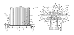
- FIG. 1 is a side view of a stoker fired boiler with a traveling grate stoker
- FIG. 2 is a cross sectional view of a seal for a traveling grate stoker
- FIG. 3 is a side view of two of the seals of FIG. 2 ;
- FIG. 4 is a top view of portions of two of the stationary seal portions of FIG. 2 .
- a stoker fired boiler 10 includes an interior area 12 defined by a plurality of water wall tubes 14 having external portions thereof connected to one another.
- the boiler 10 includes multiple fuel inlets 16 for conveying fuel such as coal or biomass into the interior area 12 for combustion therein.
- the boiler 10 also includes a traveling grate stoker 18 disposed in a bottom portion 21 of the boiler and mounted to a foundation underneath the boiler.
- the traveling grate stoker 18 conveys fuel on a conveying surface 32 of the traveling grate stoker.
- the traveling grate stoker 18 also regulates the flow of air from an undergrate portion 20 of the boiler 10 thereby ensuring that a sufficient amount of the air is available for combustion of the fuel in the boiler and on the traveling grate surface 32 .
- the traveling grate stoker 18 includes a seal 22 defined by a stationary seal portion 24 which sealingly cooperates with a plurality of plate assemblies 26 as the plate assemblies successively travel over the stationary seal portion.
- each of the plate assemblies 26 include end key plates (not shown) with a plurality of grate bars 30 disposed therebetween.
- the grate bars 30 and the end key plates cooperate with each other to define conveying surfaces 32 for conveying a fuel 34 disposed thereon, such as coal or biomass, into the interior area 12 of the boiler 10 for combustion.
- the grate bars 30 communicate with a drive mechanism 29 , such as a chain conveyor, for movement of the plate assemblies 26 and fuel 34 through the interior area 12 in a travel direction T.
- the stationary seal portion 24 and the plate assemblies 26 define gaps G 1 and G 2 therebetween.
- the fuel 34 is combusted on the conveying surfaces 32 in an oxygen rich area 38 of the interior area 18 of the boiler 10 , located generally above the conveying surface.
- the combustion process creates byproducts 40 , such as ash and other abrasive materials, some of which can accumulate on the stationary seal portion 24 adjacent to the gap G 1 .
- the seal 22 has utility in mitigating the introduction of the byproducts 40 into the gaps G 1 and G 2 and between the stationary seal portion 24 and the plate assemblies 26 , reducing wear and thereby prolonging the life of the seal.
- the stationary seal portion 24 is defined by two generally parallel legs 42 and an integral base portion 44 .
- the stationary seal portion 24 is secured to the stationary base by suitable fasteners (not shown) communicating with the base portion 44 .
- the legs 42 and the base portion 44 collectively define a channel 46 therebetween.
- the channel 46 has a generally U-shaped configuration and terminates at an opening 48 between free ends 50 of the legs 42 .
- the channel 46 can be of any suitable size or shape.
- the legs 42 while being shown and described as being integral with the base 44 , are not limited in this regard as the legs can also be secured to the base and/or another stationary element by suitable fasteners, welding or a combination thereof.
- the legs 42 are shown and described as being parallel, the illustrated embodiment is not limited in this regard as any number of legs, of any configuration can be employed including but not limited to curvilinear legs and more than two legs.
- Each of the legs 42 includes a flange 52 extending outwardly from a distal end 42 E of each leg.
- Each of the flanges 52 define a surface 53 extending from the respective leg 42 to a lateral edge 52 L and extending between leading 52 A and trailing edges 52 B (i.e., distal edges or distal ends) of the flange 52 .
- the lateral edge 52 L is generally parallel to the leg 42 ; and the leading 52 A and trailing 52 B edges are generally perpendicular to the lateral edge 52 L.
- Each of the surfaces 53 include a sealing portion 55 positioned adjacent to the leg 42 .
- the surface 53 and in particular the sealing portion 55 of the flange 52 is positioned in close proximity to an underside 26 U of the plate assemblies 26 to seal the gap G 2 therebetween.
- Each of the legs 42 includes an extension 36 projecting upwardly from the distal end 42 E of each leg and having an edge 36 E that is approximately flush with the conveying surface 32 of the traveling grate 18 .
- the extensions 36 includes an outwardly facing side portion which defines a sealing surface 59 which is generally parallel to and positioned in close proximity to an edge 26 E of each of the plurality of plate assemblies 26 to seal the gap G 1 therebetween.
- the extension 36 serves as a dam to prevent the combustion byproducts 40 from migrating laterally into the gap G 2 , from the channel 46 .
- the sealing portion 55 of the surface 53 of the flange 42 is positioned adjacent to the extension 36 .
- the surface 53 of the flange 52 is sloped downwardly from a junction between the sealing portion 55 and the extension 36 at an angle S of about eight degrees with respect to a horizontal reference line H.
- Such a configuration defines a progressively increasing opening 56 between the flange 52 and the underside 26 U of each of the plate assemblies 26 .
- the opening 56 defines an outlet or side-discharge portion for discharge of the byproducts 40 which may have been introduced into the opening through the gaps G 1 and G 2 .
- the slope of the flange 52 facilitates gravity forced movement and/or self cleaning of the byproducts 40 off the flange and out of the opening. Removal of the byproducts 40 from the flange 26 reduces wear and extends the life of the seal.
- upwardly facing surface 53 is shown in the illustrated embodiment at an angle sloped downwardly eight degrees from the horizontal, the slope is not limited in this regard as other configurations including but not limited to any downwardly sloped angle, surfaces having multiple slopes, portions being horizontal, portions having curved surfaces and combinations thereof can be employed without departing from the broader aspects disclosed herein.
- a peripheral portion of the surface 53 of the flange 52 is downwardly curved to the leading 52 A and the trailing 52 B edges of each of the flanges 52 .
- the downward curvature creates a gravity driven path Q (i.e., end-discharge portion) for discharge or self cleaning of the byproducts 40 away from the bearing surface 55 .
- Q gravity driven path
- carryover of the byproducts 40 from one flange 52 to an adjacent downstream flange and seal 22 is mitigated, thereby reducing the potential for wear of the seal.
- peripheral portion of the surface 53 of the flange 52 is shown and described as being downwardly curved towards both the leading 52 A and the trailing 52 B edges, other embodiments can be employed including but not limited to the peripheral portion of the surface 53 being curved and/or linearly sloped downwardly to only one of the leading 52 A and the trailing 52 B edges, while the other end is horizontal.
- each of the stationary seal portions 24 include two gusset members 60 disposed in the channel 46 and integral with the legs 42 and base 44 .
- Each of the gusset members 60 extends from the base 44 to a distal end 60 E positioned below a conveying surface 32 of the traveling grate 18 and serves as a support member between the legs 42 .
- the channel 46 Prior to operation, the channel 46 is filled with sand for insulating purposes.
- the gussets members 60 create local dams to maintain the sand in and serve to stiffen the channel 46 . While the stationary seal portions 24 are shown and described as having two gusset members 60 it is contemplated that any number of gusset members can be employed.
- the gusset members are shown and described as being integral with the legs 42 and base 44 , the present embodiment is not limited in this regard as separate gusset members can be employed and installed with fasteners and/or by welding. While the gusset members are shown and described as extending from the base 44 to a distal end 60 E positioned below a conveying surface 32 of the traveling grate, the present invention is not limited in this regard as gusset members of other lengths can be employed including but not limited to those which protrude out of the channel 46 beyond the extensions 36 and those which are about flush with the conveying surface 32 .
- the byproducts 40 swirl around in the interior area 12 in multiple directions A. A portion of the byproducts 40 settles on top of the sand in channel 46 and between the extensions 36 . After a period of operation, as a result of a damming action by the extensions 36 , the byproducts 40 form a pile P above the channel 46 and the conveying surface 32 . After a further period of operation, the byproducts 40 fall off the pile P as shown by arrow B, onto the plate assemblies 26 , which carry the byproducts away from the gaps G 1 .
- the extensions 36 provide a dam or barrier mitigating lateral movement of the byproducts 40 into the gaps G 1 and G 2 , the pile P protrudes above the conveying surface 32 and the byproducts 40 fall onto and are carried away by the plate assemblies 26 . Therefore, migration of the byproducts 40 into the seal 22 is mitigated. Reducing the migration of the byproducts 40 into the seal 22 reduces wear and increases life of the seal.
- a male connector 70 extends laterally from and is integral with an inside portion 42 C of each leg 42 .
- each of the male connectors 70 protrude into a female mating portion 46 F defined by opposing inside portions 42 D of each leg 42 .
- the male connectors 70 and female mating portions 46 F are sized to accommodate thermal expansion of the stationary seal portions 24 .
- Use of the stationary seal portions 24 with the integral male connectors reduces manufacturing costs and facilitates assembly. While the stationary seal portions 24 are shown and described as having two male connectors 70 , it is contemplated that the any number of connectors located on inner, outer and/or bottom surfaces of the stationary seal portions can be employed.
Landscapes
- Engineering & Computer Science (AREA)
- Chemical & Material Sciences (AREA)
- Combustion & Propulsion (AREA)
- Mechanical Engineering (AREA)
- General Engineering & Computer Science (AREA)
- Incineration Of Waste (AREA)
Abstract
Description
Claims (13)
Priority Applications (2)
| Application Number | Priority Date | Filing Date | Title |
|---|---|---|---|
| US12/916,983 US9163833B2 (en) | 2010-11-01 | 2010-11-01 | Reduced wear and self cleaning stoker seal |
| CA2756515A CA2756515C (en) | 2010-11-01 | 2011-10-26 | Reduced wear and self cleaning stoker seal |
Applications Claiming Priority (1)
| Application Number | Priority Date | Filing Date | Title |
|---|---|---|---|
| US12/916,983 US9163833B2 (en) | 2010-11-01 | 2010-11-01 | Reduced wear and self cleaning stoker seal |
Publications (2)
| Publication Number | Publication Date |
|---|---|
| US20120103236A1 US20120103236A1 (en) | 2012-05-03 |
| US9163833B2 true US9163833B2 (en) | 2015-10-20 |
Family
ID=45995251
Family Applications (1)
| Application Number | Title | Priority Date | Filing Date |
|---|---|---|---|
| US12/916,983 Expired - Fee Related US9163833B2 (en) | 2010-11-01 | 2010-11-01 | Reduced wear and self cleaning stoker seal |
Country Status (2)
| Country | Link |
|---|---|
| US (1) | US9163833B2 (en) |
| CA (1) | CA2756515C (en) |
Families Citing this family (1)
| Publication number | Priority date | Publication date | Assignee | Title |
|---|---|---|---|---|
| CN106196616A (en) * | 2016-06-29 | 2016-12-07 | 无锡锡能锅炉有限公司 | A kind of boiler plant automatically controlled |
Citations (4)
| Publication number | Priority date | Publication date | Assignee | Title |
|---|---|---|---|---|
| US1660217A (en) * | 1924-03-11 | 1928-02-21 | Bennis Alfred William | Chain-grate stoker |
| US2806439A (en) * | 1952-11-08 | 1957-09-17 | Detroit Stoker Co | Grate |
| US3665668A (en) * | 1970-03-03 | 1972-05-30 | Orville Lee Maddan Jr | Construction joint for buildings and the like |
| US8070004B2 (en) * | 2008-11-24 | 2011-12-06 | Institute Of International Container Lessors | Container flooring system |
-
2010
- 2010-11-01 US US12/916,983 patent/US9163833B2/en not_active Expired - Fee Related
-
2011
- 2011-10-26 CA CA2756515A patent/CA2756515C/en not_active Expired - Fee Related
Patent Citations (4)
| Publication number | Priority date | Publication date | Assignee | Title |
|---|---|---|---|---|
| US1660217A (en) * | 1924-03-11 | 1928-02-21 | Bennis Alfred William | Chain-grate stoker |
| US2806439A (en) * | 1952-11-08 | 1957-09-17 | Detroit Stoker Co | Grate |
| US3665668A (en) * | 1970-03-03 | 1972-05-30 | Orville Lee Maddan Jr | Construction joint for buildings and the like |
| US8070004B2 (en) * | 2008-11-24 | 2011-12-06 | Institute Of International Container Lessors | Container flooring system |
Also Published As
| Publication number | Publication date |
|---|---|
| CA2756515C (en) | 2015-08-11 |
| CA2756515A1 (en) | 2012-05-01 |
| US20120103236A1 (en) | 2012-05-03 |
Similar Documents
| Publication | Publication Date | Title |
|---|---|---|
| US8707876B2 (en) | Stepped floor for solid fuel boilers | |
| US7886457B2 (en) | Cooler for bulk material having a sealing device between adjoining conveying planks | |
| JP6260058B2 (en) | Stoker-type incinerator | |
| US6263837B1 (en) | Grate construction of a fluidized bed boiler | |
| US9163833B2 (en) | Reduced wear and self cleaning stoker seal | |
| EP2480830A2 (en) | System for extraction and transport of light ashes by means of a steel belt conveyor | |
| JP2010139176A (en) | Inverted low nox boiler | |
| AU721298B2 (en) | Boundary layer coal nozzle assembly for steam generation apparatus | |
| US20180142955A1 (en) | Clinker inlet distribution of a cement clinker cooler | |
| US4475468A (en) | Incinerator with moving-bed stoker | |
| US7146916B2 (en) | Starved air inclined hearth combustor | |
| US20120180708A1 (en) | Boiler grate and a boiler | |
| US4774908A (en) | Dry ash handling system | |
| KR200429257Y1 (en) | Grate for incinerator | |
| CN107664307B (en) | Alternately moving fire grate garbage incinerator | |
| CN102815504B (en) | Anti-scattering structure for bulk material conveying device | |
| KR101059543B1 (en) | Pulverized coal inflow prevention device for conveying air duct in bowl mill | |
| KR101672444B1 (en) | Self cooling type high efficiency stoker equipment | |
| KR101054561B1 (en) | Grate structure to prevent clinker attachment | |
| KR960004892Y1 (en) | Grate | |
| CN206637615U (en) | CFBB N-type returning charge valve | |
| RU2231714C2 (en) | Furnace for burning solid fuel in fluidized bed | |
| JP5243884B2 (en) | Sintering machine pallet | |
| EP0087531B1 (en) | Grate assembly in solid fuel combustion equipments | |
| RU2456511C1 (en) | Coal-fired boiler |
Legal Events
| Date | Code | Title | Description |
|---|---|---|---|
| AS | Assignment |
Owner name: ALSTOM TECHNOLOGY LTD., SWITZERLAND Free format text: ASSIGNMENT OF ASSIGNORS INTEREST;ASSIGNORS:GIBOWSKI, STEVEN R.;SEMYANKO, IVAN;REEL/FRAME:025228/0194 Effective date: 20101029 |
|
| AS | Assignment |
Owner name: ALSTOM TECHNOLOGY LTD, SWITZERLAND Free format text: ASSIGNMENT OF ASSIGNORS INTEREST;ASSIGNOR:CABAN, ISRAEL;REEL/FRAME:026604/0562 Effective date: 20110622 |
|
| AS | Assignment |
Owner name: ALSTOM TECHNOLOGY LTD., SWITZERLAND Free format text: ASSIGNMENT OF ASSIGNORS INTEREST;ASSIGNOR:ZAK, JEFFREY M.;REEL/FRAME:027113/0610 Effective date: 20111007 |
|
| FEPP | Fee payment procedure |
Free format text: PAYOR NUMBER ASSIGNED (ORIGINAL EVENT CODE: ASPN); ENTITY STATUS OF PATENT OWNER: LARGE ENTITY |
|
| STCF | Information on status: patent grant |
Free format text: PATENTED CASE |
|
| AS | Assignment |
Owner name: GENERAL ELECTRIC TECHNOLOGY GMBH, SWITZERLAND Free format text: CHANGE OF NAME;ASSIGNOR:ALSTOM TECHNOLOGY LTD;REEL/FRAME:039714/0578 Effective date: 20151102 |
|
| FEPP | Fee payment procedure |
Free format text: MAINTENANCE FEE REMINDER MAILED (ORIGINAL EVENT CODE: REM.); ENTITY STATUS OF PATENT OWNER: LARGE ENTITY |
|
| LAPS | Lapse for failure to pay maintenance fees |
Free format text: PATENT EXPIRED FOR FAILURE TO PAY MAINTENANCE FEES (ORIGINAL EVENT CODE: EXP.); ENTITY STATUS OF PATENT OWNER: LARGE ENTITY |
|
| STCH | Information on status: patent discontinuation |
Free format text: PATENT EXPIRED DUE TO NONPAYMENT OF MAINTENANCE FEES UNDER 37 CFR 1.362 |
|
| FP | Lapsed due to failure to pay maintenance fee |
Effective date: 20191020 |