US9163004B2 - Organic light-emitting device - Google Patents

Organic light-emitting device Download PDF

Info

Publication number
US9163004B2
US9163004B2 US13/164,348 US201113164348A US9163004B2 US 9163004 B2 US9163004 B2 US 9163004B2 US 201113164348 A US201113164348 A US 201113164348A US 9163004 B2 US9163004 B2 US 9163004B2
Authority
US
United States
Prior art keywords
group
layer
organic light
emitting device
electrode
Prior art date
Legal status (The legal status is an assumption and is not a legal conclusion. Google has not performed a legal analysis and makes no representation as to the accuracy of the status listed.)
Active, expires
Application number
US13/164,348
Other versions
US20110309348A1 (en
Inventor
Yoon-Hyun Kwak
Seok-Hwan Hwang
Young-Kook Kim
Hye-jin Jung
Jong-hyuk Lee
Hee-Joo Ko
Current Assignee (The listed assignees may be inaccurate. Google has not performed a legal analysis and makes no representation or warranty as to the accuracy of the list.)
Samsung Display Co Ltd
Original Assignee
Samsung Display Co Ltd
Priority date (The priority date is an assumption and is not a legal conclusion. Google has not performed a legal analysis and makes no representation as to the accuracy of the date listed.)
Filing date
Publication date
Application filed by Samsung Display Co Ltd filed Critical Samsung Display Co Ltd
Assigned to SAMSUNG MOBILE DISPLAY CO., LTD. reassignment SAMSUNG MOBILE DISPLAY CO., LTD. ASSIGNMENT OF ASSIGNORS INTEREST (SEE DOCUMENT FOR DETAILS). Assignors: HWANG, SEOK-HWAN, JUNG, HYE-JIN, KIM, YOUNG-KOOK, KO, HEE-JOO, KWAK, YOON-HYUN, LEE, JONG-HYUK
Publication of US20110309348A1 publication Critical patent/US20110309348A1/en
Assigned to SAMSUNG DISPLAY CO., LTD. reassignment SAMSUNG DISPLAY CO., LTD. MERGER (SEE DOCUMENT FOR DETAILS). Assignors: SAMSUNG MOBILE DISPLAY CO., LTD.
Application granted granted Critical
Publication of US9163004B2 publication Critical patent/US9163004B2/en
Active legal-status Critical Current
Adjusted expiration legal-status Critical

Links

Images

Classifications

    • HELECTRICITY
    • H10SEMICONDUCTOR DEVICES; ELECTRIC SOLID-STATE DEVICES NOT OTHERWISE PROVIDED FOR
    • H10KORGANIC ELECTRIC SOLID-STATE DEVICES
    • H10K85/00Organic materials used in the body or electrodes of devices covered by this subclass
    • H10K85/60Organic compounds having low molecular weight
    • H10K85/649Aromatic compounds comprising a hetero atom
    • H10K85/657Polycyclic condensed heteroaromatic hydrocarbons
    • H10K85/6572Polycyclic condensed heteroaromatic hydrocarbons comprising only nitrogen in the heteroaromatic polycondensed ring system, e.g. phenanthroline or carbazole
    • CCHEMISTRY; METALLURGY
    • C07ORGANIC CHEMISTRY
    • C07DHETEROCYCLIC COMPOUNDS
    • C07D401/00Heterocyclic compounds containing two or more hetero rings, having nitrogen atoms as the only ring hetero atoms, at least one ring being a six-membered ring with only one nitrogen atom
    • C07D401/14Heterocyclic compounds containing two or more hetero rings, having nitrogen atoms as the only ring hetero atoms, at least one ring being a six-membered ring with only one nitrogen atom containing three or more hetero rings
    • CCHEMISTRY; METALLURGY
    • C07ORGANIC CHEMISTRY
    • C07DHETEROCYCLIC COMPOUNDS
    • C07D209/00Heterocyclic compounds containing five-membered rings, condensed with other rings, with one nitrogen atom as the only ring hetero atom
    • C07D209/02Heterocyclic compounds containing five-membered rings, condensed with other rings, with one nitrogen atom as the only ring hetero atom condensed with one carbocyclic ring
    • C07D209/04Indoles; Hydrogenated indoles
    • C07D209/08Indoles; Hydrogenated indoles with only hydrogen atoms or radicals containing only hydrogen and carbon atoms, directly attached to carbon atoms of the hetero ring
    • CCHEMISTRY; METALLURGY
    • C07ORGANIC CHEMISTRY
    • C07DHETEROCYCLIC COMPOUNDS
    • C07D209/00Heterocyclic compounds containing five-membered rings, condensed with other rings, with one nitrogen atom as the only ring hetero atom
    • C07D209/56Ring systems containing three or more rings
    • C07D209/58[b]- or [c]-condensed
    • C07D209/60Naphtho [b] pyrroles; Hydrogenated naphtho [b] pyrroles
    • CCHEMISTRY; METALLURGY
    • C07ORGANIC CHEMISTRY
    • C07DHETEROCYCLIC COMPOUNDS
    • C07D403/00Heterocyclic compounds containing two or more hetero rings, having nitrogen atoms as the only ring hetero atoms, not provided for by group C07D401/00
    • C07D403/02Heterocyclic compounds containing two or more hetero rings, having nitrogen atoms as the only ring hetero atoms, not provided for by group C07D401/00 containing two hetero rings
    • C07D403/10Heterocyclic compounds containing two or more hetero rings, having nitrogen atoms as the only ring hetero atoms, not provided for by group C07D401/00 containing two hetero rings linked by a carbon chain containing aromatic rings
    • CCHEMISTRY; METALLURGY
    • C07ORGANIC CHEMISTRY
    • C07DHETEROCYCLIC COMPOUNDS
    • C07D413/00Heterocyclic compounds containing two or more hetero rings, at least one ring having nitrogen and oxygen atoms as the only ring hetero atoms
    • C07D413/02Heterocyclic compounds containing two or more hetero rings, at least one ring having nitrogen and oxygen atoms as the only ring hetero atoms containing two hetero rings
    • C07D413/10Heterocyclic compounds containing two or more hetero rings, at least one ring having nitrogen and oxygen atoms as the only ring hetero atoms containing two hetero rings linked by a carbon chain containing aromatic rings
    • CCHEMISTRY; METALLURGY
    • C07ORGANIC CHEMISTRY
    • C07DHETEROCYCLIC COMPOUNDS
    • C07D471/00Heterocyclic compounds containing nitrogen atoms as the only ring hetero atoms in the condensed system, at least one ring being a six-membered ring with one nitrogen atom, not provided for by groups C07D451/00 - C07D463/00
    • C07D471/02Heterocyclic compounds containing nitrogen atoms as the only ring hetero atoms in the condensed system, at least one ring being a six-membered ring with one nitrogen atom, not provided for by groups C07D451/00 - C07D463/00 in which the condensed system contains two hetero rings
    • C07D471/04Ortho-condensed systems
    • CCHEMISTRY; METALLURGY
    • C07ORGANIC CHEMISTRY
    • C07DHETEROCYCLIC COMPOUNDS
    • C07D487/00Heterocyclic compounds containing nitrogen atoms as the only ring hetero atoms in the condensed system, not provided for by groups C07D451/00 - C07D477/00
    • C07D487/02Heterocyclic compounds containing nitrogen atoms as the only ring hetero atoms in the condensed system, not provided for by groups C07D451/00 - C07D477/00 in which the condensed system contains two hetero rings
    • C07D487/04Ortho-condensed systems
    • CCHEMISTRY; METALLURGY
    • C07ORGANIC CHEMISTRY
    • C07DHETEROCYCLIC COMPOUNDS
    • C07D519/00Heterocyclic compounds containing more than one system of two or more relevant hetero rings condensed among themselves or condensed with a common carbocyclic ring system not provided for in groups C07D453/00 or C07D455/00
    • H01L51/0067
    • H01L51/0072
    • HELECTRICITY
    • H10SEMICONDUCTOR DEVICES; ELECTRIC SOLID-STATE DEVICES NOT OTHERWISE PROVIDED FOR
    • H10KORGANIC ELECTRIC SOLID-STATE DEVICES
    • H10K50/00Organic light-emitting devices
    • H10K50/10OLEDs or polymer light-emitting diodes [PLED]
    • H10K50/14Carrier transporting layers
    • H10K50/16Electron transporting layers
    • HELECTRICITY
    • H10SEMICONDUCTOR DEVICES; ELECTRIC SOLID-STATE DEVICES NOT OTHERWISE PROVIDED FOR
    • H10KORGANIC ELECTRIC SOLID-STATE DEVICES
    • H10K85/00Organic materials used in the body or electrodes of devices covered by this subclass
    • H10K85/30Coordination compounds
    • H10K85/321Metal complexes comprising a group IIIA element, e.g. Tris (8-hydroxyquinoline) gallium [Gaq3]
    • H10K85/324Metal complexes comprising a group IIIA element, e.g. Tris (8-hydroxyquinoline) gallium [Gaq3] comprising aluminium, e.g. Alq3
    • HELECTRICITY
    • H10SEMICONDUCTOR DEVICES; ELECTRIC SOLID-STATE DEVICES NOT OTHERWISE PROVIDED FOR
    • H10KORGANIC ELECTRIC SOLID-STATE DEVICES
    • H10K85/00Organic materials used in the body or electrodes of devices covered by this subclass
    • H10K85/60Organic compounds having low molecular weight
    • H10K85/649Aromatic compounds comprising a hetero atom
    • H10K85/654Aromatic compounds comprising a hetero atom comprising only nitrogen as heteroatom
    • H01L2251/308
    • H01L51/0081
    • H01L51/5072
    • HELECTRICITY
    • H10SEMICONDUCTOR DEVICES; ELECTRIC SOLID-STATE DEVICES NOT OTHERWISE PROVIDED FOR
    • H10KORGANIC ELECTRIC SOLID-STATE DEVICES
    • H10K2102/00Constructional details relating to the organic devices covered by this subclass
    • HELECTRICITY
    • H10SEMICONDUCTOR DEVICES; ELECTRIC SOLID-STATE DEVICES NOT OTHERWISE PROVIDED FOR
    • H10KORGANIC ELECTRIC SOLID-STATE DEVICES
    • H10K2102/00Constructional details relating to the organic devices covered by this subclass
    • H10K2102/10Transparent electrodes, e.g. using graphene
    • H10K2102/101Transparent electrodes, e.g. using graphene comprising transparent conductive oxides [TCO]
    • H10K2102/103Transparent electrodes, e.g. using graphene comprising transparent conductive oxides [TCO] comprising indium oxides, e.g. ITO

Definitions

  • the present embodiments relate to a heterocyclic compound represented by Formula 1 and an organic light-emitting device including the heterocyclic compound.
  • Organic light-emitting devices are self-emitting display devices and have wide viewing angles, high contrast ratios, and short response times. Due to these characteristics, organic light-emitting devices are drawing more attention.
  • Such light-emitting devices can be roughly classified into inorganic light-emitting devices that include emission layers containing inorganic compounds, and organic light-emitting devices that include emission layers containing organic compounds. Specifically, organic light-emitting devices have higher luminance, lower driving voltages, and shorter response times than inorganic light-emitting devices, and can render multi-colored displays. Thus, much research into such organic light-emitting devices has been conducted.
  • an organic light-emitting device has a stack structure including an anode, a cathode and an organic emission layer between the anode and the cathode.
  • a hole injection layer and/or a hole transport layer may be further stacked between the anode and the organic emission layer, and/or an electron transport layer may be further stacked between the organic emission layer and the cathode.
  • An organic light-emitting device may have an anode/hole transport layer/organic emission layer/cathode structure or an anode/hole transport layer/organic emission layer/electron transport layer/cathode structure.
  • organic emission layer As a material for the organic emission layer, a phenanthrene derivative may be used.
  • organic light-emitting devices including such as known organic emission materials do not have satisfactory life span, efficiency, and power consumption characteristics.
  • the present embodiments provide a heterocyclic compound having improved electrical characteristics, charge transporting capabilities and light-emission capabilities.
  • the present embodiments provide an organic light-emitting device including the heterocyclic compound.
  • the present embodiments provide a flat panel display device including the organic light-emitting device.
  • the present embodiments provide an organic light-emitting device including at least one layer containing the heterocyclic compound, wherein the at least one layer is formed using a wet process.
  • R 1 through R 9 may be each independently a hydrogen atom, a heavy hydrogen atom, a substituted or unsubstituted C 1 -C 50 alkyl group, a substituted or unsubstituted C 3 -C 50 cycloalkyl group, a substituted or unsubstituted C 1 -C 50 alkoxy group, a substituted or unsubstituted C 5 -C 50 aryloxy group, a substituted or unsubstituted C 5 -C 50 arylthio group, a substituted or unsubstituted C 5 -C 60 aryl group, a substituted amino group with a R 5 -R 60 aryl group, a substituted or unsubstituted C 3 -C 60 heteroaryl group, a substituted or unsubstituted C 6 -C 60 condensed polycyclic group, a halogen atom, a cyano group, a nitro group, a hydroxyl
  • R 1 , R 2 , R 3 or R 6 may be an aryl group.
  • R 6 may be an unsubstituted monocyclic to tetracyclic aryl group selected from the group consisting of a phenyl group, a naphthyl group, a biphenyl group, a terphenyl group, an anthracenyl group, a fluorenyl group, a carbazolyl group, and a pyrenyl group; an unsubstituted C 3 -C 60 heteroaryl group; an unsubstituted C 5 -C 50 arylamine group; a substituted monocyclic to tetracyclic aryl group selected from the group consisting of a phenyl group, a naphthyl group, a biphenyl group, a terphenyl group, an anthracenyl group, a fluorenyl group, a carbazolyl group, and a pyrenyl group which are optionally substituted with a C 1 -C 5 alkyl group,
  • R 1 may be an unsubstituted monocyclic to tetracyclic aryl group selected from the group consisting of a phenyl group, a naphthyl group, a biphenyl group, a terphenyl group, an anthracenyl group, a fluorenyl group, a carbazolyl group, and a pyrenyl group; an unsubstituted C 3 -C 60 heteroaryl group; a substituted monocyclic to tetracyclic aryl group selected from the group consisting of a phenyl group, a naphthyl group, a biphenyl group, a terphenyl group, an anthracenyl group, a fluorenyl group, a carbazolyl group, and a pyrenyl group which are optionally substituted with a C 1 -C 5 alkyl group, a C 1 -C 5 alkoxy group, a cyano group,
  • R 2 and R 3 may be each independently a methyl group or a phenyl group.
  • the heterocyclic compound may include one of the compounds below:
  • an organic light-emitting device including: a first electrode; a second electrode; and an organic layer between the first electrode and the second electrode, wherein the organic layer includes at least one layer including the above heterocyclic compound.
  • the organic layer may include an electron injection layer or an electron transport layer.
  • the organic layer may include a single layer having both an electron injection function and an electron transport function.
  • the organic layer may include an emission layer.
  • the organic layer may include an emission layer, and the heterocylic compound may be used as a host for a fluorescent or phosphorescent device.
  • the organic layer may include an emission layer, and the heterocylic compound may be used as a fluorescent dopant.
  • the emission layer, the electron injection layer, or the electron transport layer of the organic light-emitting device may include the heterocyclic compound, wherein the emission layer may include an anthracene compound, or a styryl compound.
  • the electron injection layer or the electron transport layer of the organic light-emitting device may include the heterocyclic compound, and a red emission layer, a green emission layer, a blue emission layer, or a white emission layer may include a phosphorescent compound.
  • the organic layer may include at least one layer selected from the group consisting of a hole injection layer, a hole transport layer, an electron blocking layer, an emission layer, a hole blocking layer, an electron transport layer, and an electron injection layer.
  • the organic light-emitting device may have a first electrode/hole injection layer/emission layer/second electrode structure, a first electrode/hole injection layer/hole transport layer/emission layer/electron transport layer/second electrode structure, or a first electrode/hole injection layer/hole transport layer/emission layer/electron transport structure layer/electron injection layer/second electrode structure.
  • a flat panel display device including the above organic light-emitting device, wherein the first electrode of the organic light-emitting device is electrically connected to a source electrode or a drain electrode of a thin-film transistor.
  • an organic light-emitting device including: a first electrode; a second electrode; and an organic layer between the first electrode and the second electrode, wherein the organic layer includes at least one layer including the above heterocyclic compound, the at least one layer being formed using a wet process.
  • FIG. 1 is a diagram of the structure of an organic light-emitting device according to an embodiment.
  • a heterocyclic compound according to an embodiment is represented by Formula 1 below:
  • R 1 through R 9 are each independently a hydrogen atom, a heavy hydrogen atom (deuterium or tritium), a substituted or unsubstituted C 1 -C 50 alkyl group, a substituted or unsubstituted C 3 -C 50 cycloalkyl group, a substituted or unsubstituted C 1 -C 50 alkoxy group, a substituted or unsubstituted C 5 -C 50 aryloxy group, a substituted or unsubstituted C 5 -C 50 arylthio group, a substituted or unsubstituted C 5 -C 60 aryl group, a substituted amino group with a R 5 -R 60 aryl group, a substituted or unsubstituted C 3 -C 60 heteroaryl group, a substituted or unsubstituted C 6 -C 60 condensed polycyclic group, a halogen atom, a cyano group, a nitro
  • Examples of materials for forming an emission layer or an electron transport layer, which constitute an organic light-emitting device include, but are not limited to, Alq3, 2,2′,2′′-(1,3,5-phenylene)tris-(1-phenyl)-1H-benzimidazol (TPBI), 2-Biphenyl-4-yl-5-(4-tert-butyl-phenyl)-[1,3,4]oxadiazole (PBD), perfluorinated chemical (PF-6P), and 2,5-bis(6′-(2′,2′′-bipyridyl))-1,1-dimethyl-3,4-diphenylsiylol (PyPySPyPy).
  • TPBI Alq3, 2,2′,2′′-(1,3,5-phenylene)tris-(1-phenyl)-1H-benzimidazol
  • PBD 2-Biphenyl-4-yl-5-(4-tert-butyl-phenyl)
  • An organic light-emitting device manufactured using the heterocyclic compound of Formula 1, in which a phenenthrene group and an indole group are fused has excellent durability when stored or operated.
  • a substituent such as a fluorene group or a naphthyl group
  • molecular layers formed as thin films may be maintained in good condition, thereby improving the characteristics of the organic light-emitting device.
  • R 1 , R 2 , R 3 or R 6 may be an aryl group.
  • the aryl group may be substituted with a substituent described later in conjunction with the C 1 -C 50 alkyl group.
  • R 6 may be an unsubstituted monocyclic to tetracyclic aryl group selected from the group consisting of a phenyl group, a naphthyl group, a biphenyl group, a terphenyl group, an anthracenyl group, a fluorenyl group, a carbazolyl group, and a pyrenyl group; an unsubstituted C 3 -C 60 heteroaryl group; an unsubstituted C 5 -C 50 arylamine group; a substituted monocyclic to tetracyclic aryl group selected from the group consisting of a phenyl group, a naphthyl group, a biphenyl group, a terphenyl group, an anthracenyl group, a fluorenyl group, a carbazolyl group, and a pyrenyl group which are optionally substituted with a C 1 -C 5 alkyl group,
  • R 1 may be an unsubstituted monocyclic to tetracyclic aryl group selected from the group consisting of a phenyl group, a naphthyl group, a biphenyl group, a terphenyl group, an anthracenyl group, a fluorenyl group, a carbazolyl group, and a pyrenyl group; an unsubstituted C 3 -C 60 heteroaryl group; a substituted monocyclic to tetracyclic aryl group selected from the group consisting of a phenyl group, a naphthyl group, a biphenyl group, a terphenyl group, an anthracenyl group, a fluorenyl group, a carbazolyl group, and a pyrenyl group which are optionally substituted with a C 1 -C 5 alkyl group, a C 1 -C 5 alkoxy group, a cyano group,
  • R 2 and R 3 may be each independently a methyl group or a phenyl group.
  • the unsubstituted C 1 -C 50 alkyl group used herein may be linear or branched.
  • Examples of the unsubstituted C 1 -C 50 alkyl group include, but are not limited to, a methyl group, an ethyl group, a propyl group, an isobutyl group, a sec-butyl group, a pentyl group, an iso-amyl group, a hexyl group, a heptyl group, an octyl group, a nonanyl group, and a dodecyl group.
  • At least one hydrogen atom of the alkyl group may be substituted with a heavy hydrogen atom, a halogen atom, a hydroxyl group, a nitro group, a cyano group, an amino group, an amidino group, hydrazine, hydrazone, a carboxyl group or a salt thereof, a sulfonic acid group or a salt thereof, a phosphoric acid group or a salt thereof, a C 1 -C 10 alkyl group, a C 1 -C 10 alkoxy group, a C 2 -C 10 alkenyl group, a C 2 -C 10 alkynyl group, a C 6 -C 16 aryl group, or a C 3 -C 16 heteroaryl group.
  • the unsubstituted C 3 -C 50 cycloalkyl group used herein refers to a C 3 -C 50 cyclic alkyl group wherein at least one hydrogen atom in the cycloalkyl group may be substituted with a substituent such as those described above in connection with the C 1 -C 50 alkyl group.
  • the unsubstituted C 1 -C 50 alkoxy group used herein is a group having a structure of —OA wherein A is an unsubstituted C 1 -C 50 alkyl group as described above.
  • Examples of the unsubstituted C 1 -C 50 alkoxy group include, but are not limited to, a methoxy group, an ethoxy group, a propoxy group, an isopropyloxy group, a butoxy group, and a pentoxy group.
  • At least one hydrogen atom of the alkoxy group may be substituted with a substituent such as those described above in conjunction with the alkyl group.
  • the unsubstituted C 5 -C 60 aryl group used herein refers to a carbocyclic aromatic system containing at least one ring. At least two rings may be fused to each other or linked to each other by a single bond.
  • aryl refers to an aromatic system, such as phenyl, naphthyl, or anthracenyl. At least one hydrogen atom in the aryl group may be substituted with substituent such as those described above in conjunction with the C 1 -C 50 alkyl group.
  • Examples of the substituted or unsubstituted C 5 -C 60 aryl group include, but are not limited to, a phenyl group, a C 1 -C 10 alkylphenyl group (for example, an ethylphenyl group), a halophenyl group (for example, o-, m-, and p-fluorophenyl group, a dichlorophenyl group), a cyanophenyl group, dicyanophenyl group, a trifluoromethoxyphenyl group, a biphenyl group, a halobiphenyl group, a cyanobiphenyl group, a C 1 -C 10 alkyl biphenyl group, a C 1 -C 10 alkoxybiphenyl group, an o-, m-, and p-tolyl group, an o-, m-, and p-cumenyl group, a mesityl group, a phen
  • the unsubstituted C 3 -C 60 heteroaryl group used herein includes one, two or three hetero atoms selected from N, O, P and S. At least two rings may be fused to each other or linked to each other by a single bond.
  • Examples of the unsubstituted C 3 -C 60 heteroaryl group may include a pyrazolyl group, an imidazolyl group, an oxazolyl group, a thiazolyl group, a triazolyl group, a tetrazolyl group, an oxadiazolyl group, a pyridinyl group, a pyridazinyl group, a pyrimidinyl group, a triazinyl group, a carbazolyl group, an indolyl group, a quinolinyl group, and an isoquinolinyl group.
  • At least one hydrogen atom in the heteroaryl group may be substituted with a substituent such as those described above
  • the unsubstituted C 5 -C 50 aryloxy group is represented by —OA 1 wherein A 1 may be a C 5 -C 50 aryl group.
  • a 1 may be a C 5 -C 50 aryl group.
  • the aryloxy group may include a phenoxy group but are not limited to.
  • At least one hydrogen atom in the aryloxy group may be substituted with a substituent such as those described above in conjunction with the C 1 -C 50 alkyl group.
  • the unsubstituted C 5 -C 50 arylthio group is represented by —SA 1 where A 1 may be a C 5 -C 50 aryl group.
  • a 1 may be a C 5 -C 50 aryl group.
  • the arylthio group include, but are not limited to, a benzenethio group, and a naphthylthio group.
  • at least one hydrogen atom may be substituted with a substituent such as those described above in conjunction with the unsubstituted C 1 -C 50 alkyl group.
  • the unsubstituted C 6 -C 60 condensed polycyclic group used herein refers to a substituent including at least two rings wherein at least one aromatic ring and/or at least one non-aromatic ring are fused to each other.
  • the C 5 -C 50 arylamine group refers to an amine group with a C 5 -C 50 aryl group as a substituent.
  • Examples of the heterocyclic compound represented by Formula 1 may include Compounds 1 through 55 represented by the following formulae. However, the compounds represented by Formula 1 are not limited thereto.
  • An organic light-emitting device includes a first electrode, a second electrode, and an organic layer disposed between the first electrode and the second electrode, the organic layer including the heterocylic compound of Formula 1 described above.
  • the organic layer which includes the heterocyclic compound of Formula 1
  • the organic layer including the heterocyclic compound of Formula 1 may be an emission layer.
  • the heterocyclic compound of Formula 1 may be used as a host for a fluorescent or phosphorescent device or a fluorescent dopant.
  • the emission layer when the emission layer, the electron injection layer or the electron transport layer includes the heterocyclic compound of Formula 1, the emission layer may include an anthracene compound, an arylamine compound or a styryl compound, wherein the anthracene compound, the arylamine compound or the styryl compound may be unsubstituted or substituted with a substituent described above in conjunction with the C 1 -C 50 alkyl group.
  • a red emission layer, a green emission layer, a blue emission layer or a white emission layer may include a phosphorescent compound.
  • the organic layer of the organic light-emitting device may further include, but is not limited to, a hole injection layer, a hole transport layer, a functional layer having both hole injection and transport functions, an emission layer, a hole blocking layer, an electron transport layer, an electron injection layer, of a combination of at least two of these layers.
  • At least one of the hole injection layer, the hole transport layer, and the functional layer having both hole injection and transport functions may further include, in addition to the heterocylic compound of Formula 1 and widely-known hole injection and transport materials, a charge-generating material for improving conductivity of the layer.
  • the charge-generating material may include, for example, a p-dopant.
  • p-dopant include quinine derivatives, including tetracyanoquinondimethane (TCNQ) and 2,3,5,6-tetrafluoro-tetracyano-1,4-benzoquinonedimethane (F4TCNQ); metal oxides, including tungsten oxide and molybdenium oxide; and cyano group-containing compounds, including a compound represented by Formula 100 below.
  • the hole injection layer, the hole transport layer, or the functional layer having both hole injection and transport functions further includes the charge-generating material
  • the charge-generating material may be uniformly or nonuniformly distributed in the layer.
  • the electron transport layer of the organic light-emitting device may include an electron transporting organic compound and a metal-containing material.
  • the electron transporting organic compound include ADN(9,10-di(naphthalene-2-yl)anthracene); and anthracene-based compounds, including a compound of Formula 101 and a compound of Formula 102 below.
  • the metal-containing material may include a Li complex.
  • Li complex include lithium quinolate (LiQ) and a compound of Foimula 103 below.
  • the first electrode may be an anode, and the second electrode may be a cathode, but the reverse is also possible.
  • the organic layer may further include at least one layer selected from the group consisting of a hole injection layer, a hole transport layer, an electron blocking layer, an emission layer, a hole blocking layer, an electron transport layer and an electron injection layer, if required.
  • the organic light-emitting device may have a first electrode/hole injection layer/emission layer/second electrode structure, a first electrode/hole injection layer/hole transport layer/emission layer/electron transport layer/second electrode structure, or a first electrode/hole injection layer/hole transport layer/emission layer/electron transport layer/electron injection layer/second electrode structure.
  • the organic light-emitting device may have a first electrode/single layer having both hole injection and hole transport capabilities/emission layer/electron transport layer/second electrode structure, or a first electrode/single layer having both hole injection and hole transport capabilities/emission layer/electron transport layer/electron injection layer/second electrode structure.
  • the organic light-emitting device may be either a top-emission organic light-emitting device or a bottom-emission organic light-emitting device.
  • FIG. 1 illustrates the structure of an organic light-emitting device according to an embodiment.
  • the organic light-emitting device according to the present embodiment includes a substrate (not shown), a first electrode (anode), a hole injection layer (HIL), a hole transport layer (HTL), an emission layer (EML), an electron transport layer (ETL), an electron injection layer (EIL), and a second electrode (cathode).
  • HIL hole injection layer
  • HTL hole transport layer
  • EML emission layer
  • ETL electron transport layer
  • EIL electron injection layer
  • the first electrode is formed on the substrate by using a deposition or sputtering method.
  • the first electrode may comprise a first electrode material having a high work function.
  • the first electrode may constitute an anode or a cathode.
  • the substrate may be a substrate conventionally used in organic light-emitting devices, and may include, for example, a glass substrate or a transparent plastic substrate with excellent mechanical strength, thermal stability, transparency, surface smoothness, ease of handling, and water resistance.
  • the first electrode material include materials, such as indium tin oxide (ITO), indium zinc oxide (IZO), tin oxide (SnO 2 ), zinc oxide (ZnO), aluminum (Al), silver (Ag), and magnesium (Mg), which have excellent conductivity.
  • the first electrode may be formed as a transparent or reflective electrode.
  • the HIL may be formed on the first electrode using various methods, for example, vacuum deposition, spin coating, casting, Langmuir-Blodgett (LB) deposition, or the like.
  • the deposition conditions may vary according to the material used to form the HIL, and the structure and thermal characteristics of the HIL.
  • the deposition conditions may include a deposition temperature of about 100 to about 500° C., a vacuum pressure of about 10 ⁇ 8 to about 10 ⁇ 3 torr, and a deposition rate of about 0.01 to about 100 ⁇ /sec.
  • coating conditions may vary according to the material used to faun the HIL, and the structure and thermal properties of the HIL.
  • the coating conditions may include a coating rate of about 2000 rpm to about 5000 rpm, and a thermal treatment temperature of about 80° C. to about 200° C., wherein the thermal treatment serves to remove the solvent after coating.
  • the HIL may comprise any material that is commonly used to form a HIL.
  • the material that can be used to form the HIL include a phthalocyanine compound such as copper phthalocyanine, 4,4′,4′′-tris(3-methylphenylphenylamino) triphenylamine (m-MTDATA), N,N′-di(1-naphthyl)-N,N′-diphenylbenzidine (NPB), TDATA, 2-TNATA, polyaniline/dodecylbenzenesulfonic acid (Pani/DBSA), poly(3,4-ethylenedioxythiophene)/poly(4-styrenesulfonate) (PEDOT/PSS), polyaniline/camphor sulfonic acid (Pani/CSA), and polyaniline)/poly(4-styrenesulfonate (PANI/PSS), but are not limited thereto.
  • a phthalocyanine compound such as copper phthalocyan
  • the HIL may have a thickness of about 100 ⁇ to about 10000 ⁇ . When the thickness of the HIL is within these ranges, the HIL may have good hole injection characteristics without an increase in driving voltage.
  • the HTL may be formed on the HIL using various methods, for example, vacuum deposition, spin coating, casting, LB deposition, or the like.
  • the deposition or coating conditions may be similar to those used to form the HIL, though the deposition or coating conditions may vary according to the material that is used to form the HTL.
  • HTL materials may be used.
  • HTL materials include, but are not limited to, carbazole derivatives such as N-phenylcarbazole or polyvinylcarbazole, and amine derivatives having an aromatic condensed ring, such as NPB, N,N′-bis(3-methylphenyl)-N,N′-diphenyl-[1,1-biphenyl]-4,4′-diamine (TPD), or the like.
  • TCTA may not only transport holes but also inhibit excitons from being diffused from the EML.
  • the HTL may have a thickness of about 50 ⁇ to about 1000 ⁇ , for example, a thickness of about 100 ⁇ to about 600 ⁇ . When the thickness of the HTL is within these ranges, the HTL may have good hole transport characteristics without a substantial increase in driving voltage.
  • the EML may be formed on the HTL using various methods, for example, vacuum deposition, spin coating, casting, LB deposition, or the like.
  • the deposition or coating conditions may be similar to those used to form the HIL, though the deposition or coating conditions may vary according to the material that is used to form the EML.
  • the EML may include the heterocyclic compound of Formula 1 described above.
  • the heterocyclic compound of Formula 1 may be used as a host or a dopant.
  • the EML may be formed using a variety of light-emitting materials, in addition to the heterocyclic compound of Formula 1.
  • the EML may also be formed using a host and a dopant.
  • Dopants that may be used to form the EML may include either a fluorescent dopant or a phosphorescent dopant.
  • Examples of the host may include, but are not limited to, Alq3, 4,4′-N,N′-dicarbazole-biphenyl (CPB), 9,10-di(naphthalen-2-yl)anthracene (ADN), and distyrylarylene (DSA).
  • CB 4,4′-N,N′-dicarbazole-biphenyl
  • ADN 9,10-di(naphthalen-2-yl)anthracene
  • DSA distyrylarylene
  • red dopants include, but are not limited to, platinum(II) octaethylporphyrin (PtOEP), Ir(piq) 3 , Btp 2 Ir(acac), and DCJTB (4-(dicyanomethylene)-2-t-butyl-6(1,1,7,7-tetramethyljulolidyl-9-enyl)-4H-pyran).
  • PtOEP platinum(II) octaethylporphyrin
  • Ir(piq) 3 Ir(piq) 3
  • Btp 2 Ir(acac) Btp 2 Ir(acac
  • DCJTB 4-(dicyanomethylene)-2-t-butyl-6(1,1,7,7-tetramethyljulolidyl-9-enyl)-4H-pyran).
  • green dopants include, but are not limited to, Ir(ppy) 3 (where “ppy” denotes phenylpyridine), Ir(ppy) 2 (acac), Ir(mpyp) 3 , and C545T.
  • blue dopants include, but are not limited to, F 2 Irpic, (F 2 ppy) 2 Ir(tmd), Ir(dfppz) 3 , ter-fluorene, 4,4′-bis(4-diphenylaminostyryl)biphenyl (DPAVBi), and 2,5,8,11-tetra-t-butyl pherylene (TBP).
  • the amount of the dopant may be in a range of about 0.1 to about 20 parts by weight, or about 0.5 to about 12 parts by weight, based on 100 parts by weight of the EML material (which is equivalent to the total weight of the host and the dopant). When the amount of the dopant is within these ranges, concentration quenching may be substantially prevented.
  • the EML may have a thickness of about 100 ⁇ to about 1,000 ⁇ , for example, about 200 ⁇ to about 600 ⁇ . When the thickness of the EML is within these ranges, the EML may have good light-emitting characteristics without a substantial increase in driving voltage.
  • a hole blocking layer (HBL, not shown in FIG. 1 ) may be formed on the EML in order to prevent diffusion of triplet excitons or holes into the ETL.
  • HBL may comprise any material commonly used to form a HBL, without limitation. Examples of such HBL materials include, but are not limited to, oxadiazole derivatives, triazole derivatives, phenathroline derivatives, BAlq, and BCP.
  • the HBL may have a thickness of about 50 ⁇ to about 1,000 ⁇ , for example, about 100 ⁇ to about 300 ⁇ . When the thickness of the HBL is within these ranges, the HBL may have good hole blocking characteristics without a substantial increase in driving voltage.
  • the ETL is formed on the EML (or HBL) using various methods, for example, vacuum deposition, spin coating, casting, or the like.
  • the deposition or coating conditions may be similar to those used to form the HIL, though the deposition or coating conditions may vary according to the material used to form the ETL.
  • the ETL material may include the heterocyclic compound of Formula 1 described above.
  • the ETL may comprise any known material.
  • examples of the ETL material include, but are not limited to, quinoline derivatives, such as tris(8-quinolinolate)aluminum (Alq3), TAZ, and BAlq.
  • the ETL may have a thickness of about 100 ⁇ to about 1,000 ⁇ , for example, about 100 ⁇ to about 500 ⁇ . When the thickness of the ETL is within these ranges, the ETL may have good electron transport characteristics without a substantial increase in driving voltage.
  • the EIL which facilitates injection of electrons from the cathode, may be formed on the ETL.
  • the EIL may include the heterocyclic compound of Formula 1 described above.
  • EIL materials such as LiF, NaCl, CsF, Li 2 O, or BaO, may be used to form the EIL.
  • the deposition or coating conditions for forming the EIL may be similar to those applied to form the HIL, though the deposition and coating conditions may vary according to the material that is used to form the EIL.
  • the EIL may have a thickness of about 1 ⁇ to 100 ⁇ , for example, about 5 ⁇ to about 90 ⁇ . When the thickness of the EIL is within these ranges, the EIL may have good electron injection characteristics without a substantial increase in driving voltage.
  • the second electrode may be formed on the EIL by using, for example, vacuum deposition, sputtering, or the like.
  • the second electrode may be a cathode or an anode.
  • the material for forming the second electrode may include a metal, an alloy, or an electrically conductive compound, which are materials having a low work function, or a mixture thereof Examples of such materials include, but are not limited to, lithium (Li), magnesium (Mg), aluminum (Al), aluminum-lithium (Al—Li), calcium (Ca), magnesium-indium (Mg—In), and magnesium-silver (Mg—Ag).
  • a transparent cathode formed of a transparent material such as ITO or IZO may be used as the second electrode.
  • the organic light-emitting device may be included in various types of flat panel display devices, such as in a passive matrix organic light-emitting display device or in an active matrix organic light-emitting display device.
  • the first electrode on the substrate may function as a pixel electrode, electrically connected to a source electrode or a drain electrode of the thin-film transistor.
  • the organic light-emitting device may also be included in flat panel display devices having double-sided screens.
  • At least one layer of the organic light-emitting device according to the embodiment described above may comprise the heterocyclic compound of Formula 1 by using a deposition method or a wet method of coating a solution of the heterocylic compound of Formula 1.
  • An anode was prepared by cutting a Corning 15 ⁇ cm 2 (1200 ⁇ ) ITO glass substrate to a size of 50 mm ⁇ 50 mm ⁇ 0.7 mm, ultrasonically cleaning the glass substrate using isopropyl alcohol and pure water for 5 minutes each, and then irradiating UV light for 30 minutes and exposing to ozone to clean. Then, the anode was mounted in a vacuum deposition apparatus.
  • 2-TNATA which is an HIL material
  • 2-TNATA which is an HIL material
  • NPB 4,4′-bis[N-(1-naphthyl)-N-phenylamino]biphenyl
  • a green fluorescent host Alq3
  • a green fluorescent dopant C545T
  • Compound 16 was deposited on the EML to form an ETL having a thickness of about 300 ⁇ , and then LiF (which is halogenated alkali metal) was deposited on the ETL to form an EIL having a thickness of about 10 ⁇ . Then, Al was vacuum-deposited on the EIL to a thickness of about 3000 ⁇ to form a LiF/Al electrode (cathode), thereby completing the manufacture of an organic light-emitting device.
  • LiF which is halogenated alkali metal
  • the organic light-emitting device had a driving voltage of 5.97 V at a current density of 50 mA/cm 2 , a high luminosity of 8,454 cd/m 2 , color coordinates of (0.311, 0.642), and a luminescent efficiency of 16.91 cd/A.
  • An organic light-emitting device was manufactured in the same manner as in Example 1, except that Compound 25 was used instead of Compound 16 to form the ETL.
  • the organic light-emitting device had a driving voltage of 5.63 V at a current density of 50 mA/cm 2 , a high luminosity of 8,848 cd/m 2 , color coordinates of (0.310, 0.642), and a luminescent efficiency of 17.70 cd/A.
  • An organic light-emitting device was manufactured in the same manner as in Example 1, except that Compound 27 was used instead of Compound 16 to form the ETL.
  • the organic light-emitting device had a driving voltage of 5.82 V at a current density of 50 mA/cm 2 , a high luminosity of 8,376 cd/m 2 , color coordinates of (0.309, 0.643), and a luminescent efficiency of 16.75 cd/A.
  • An organic light-emitting device was manufactured in the same manner as in Example 1, except that Compound 40 was used instead of Compound 16 to form the ETL.
  • the organic light-emitting device had a driving voltage of 5.58 V at a current density of 50 mA/cm 2 , a high luminosity of 8,651 cd/m 2 , color coordinates of (0.310, 0.642), and a luminescent efficiency of 17.30 cd/A.
  • An organic light-emitting device was manufactured in the same manner as in Example 1, except that Alq3 was used, instead of Compound 16, to form the ETL.
  • the organic light-emitting device had a driving voltage of 7.45 V at a current density of 50 mA/cm 2 , a luminosity of 6,102 cd/m 2 , color coordinates of (0.309, 0.642), which are almost the same as those of Examples 1 through 4, and a luminescent efficiency of 12.2 cd/A.
  • the organic light-emitting devices including the ETL manufactured using the heterocyclic compounds of Formula 1 according to the present embodiments had a driving voltage that was lower by 1V or greater than devices manufactured using Alq3, and thus had higher efficiency and good I-V-L characteristics.
  • lifetime characteristics were markedly improved by 100% or greater in the organic light-emitting devices of Examples 1 through 4, as compared to the organic light-emitting device of Comparative Example 1.
  • novel heterocyclic compounds according to the one or more of the above embodiments have good electrical characteristics, good charge transporting capabilities and good emission characteristics, and may be used to prevent crystallization due to high glass transition temperatures (T g ).
  • the heterocyclic compounds may also be used as electron transporting materials for most color-fluorescent and phosphorescent devices, such as red, green, blue, and white fluorescent and phosphorescent devices, or as red, green, blue or white-light emitting materials.
  • an organic light-emitting device with high-efficiency, low-driving voltage, high luminance and long lifespan may be manufactured using the heterocylic compounds.

Landscapes

  • Chemical & Material Sciences (AREA)
  • Organic Chemistry (AREA)
  • Engineering & Computer Science (AREA)
  • Materials Engineering (AREA)
  • Physics & Mathematics (AREA)
  • Spectroscopy & Molecular Physics (AREA)
  • Inorganic Chemistry (AREA)
  • Optics & Photonics (AREA)
  • Electroluminescent Light Sources (AREA)
  • Plural Heterocyclic Compounds (AREA)

Abstract

A heterocyclic compound represented by Formula 1 below and an organic light-emitting device including the heterocyclic compound:
Figure US09163004-20151020-C00001
    • wherein R1 through R9 are defined as in the specification.

Description

CROSS-REFERENCE TO RELATED APPLICATIONS
This application claims the benefit of Korean Patent Application No. 10-2010-0058622, filed on Jun. 21, 2010, in the Korean Intellectual Property Office, the disclosure of which is incorporated herein in its entirety by reference.
BACKGROUND
1. Field
The present embodiments relate to a heterocyclic compound represented by Formula 1 and an organic light-emitting device including the heterocyclic compound.
2. Description of the Related Technology
Organic light-emitting devices are self-emitting display devices and have wide viewing angles, high contrast ratios, and short response times. Due to these characteristics, organic light-emitting devices are drawing more attention.
Such light-emitting devices can be roughly classified into inorganic light-emitting devices that include emission layers containing inorganic compounds, and organic light-emitting devices that include emission layers containing organic compounds. Specifically, organic light-emitting devices have higher luminance, lower driving voltages, and shorter response times than inorganic light-emitting devices, and can render multi-colored displays. Thus, much research into such organic light-emitting devices has been conducted.
Typically, an organic light-emitting device has a stack structure including an anode, a cathode and an organic emission layer between the anode and the cathode. However, a hole injection layer and/or a hole transport layer may be further stacked between the anode and the organic emission layer, and/or an electron transport layer may be further stacked between the organic emission layer and the cathode. An organic light-emitting device may have an anode/hole transport layer/organic emission layer/cathode structure or an anode/hole transport layer/organic emission layer/electron transport layer/cathode structure.
As a material for the organic emission layer, a phenanthrene derivative may be used. However, organic light-emitting devices including such as known organic emission materials do not have satisfactory life span, efficiency, and power consumption characteristics.
SUMMARY
The present embodiments provide a heterocyclic compound having improved electrical characteristics, charge transporting capabilities and light-emission capabilities.
The present embodiments provide an organic light-emitting device including the heterocyclic compound.
The present embodiments provide a flat panel display device including the organic light-emitting device.
The present embodiments provide an organic light-emitting device including at least one layer containing the heterocyclic compound, wherein the at least one layer is formed using a wet process.
According to an aspect of the present embodiments, there is provided a heterocyclic compound represented by Formula 1 below:
Figure US09163004-20151020-C00002
wherein R1 through R9 may be each independently a hydrogen atom, a heavy hydrogen atom, a substituted or unsubstituted C1-C50 alkyl group, a substituted or unsubstituted C3-C50 cycloalkyl group, a substituted or unsubstituted C1-C50 alkoxy group, a substituted or unsubstituted C5-C50 aryloxy group, a substituted or unsubstituted C5-C50 arylthio group, a substituted or unsubstituted C5-C60 aryl group, a substituted amino group with a R5-R60 aryl group, a substituted or unsubstituted C3-C60 heteroaryl group, a substituted or unsubstituted C6-C60 condensed polycyclic group, a halogen atom, a cyano group, a nitro group, a hydroxyl group, or a carboxyl group, wherein two vicinal substituents among R1 through R9 may be linked to each other to form an aromatic ring.
R1, R2, R3 or R6 may be an aryl group.
R6 may be an unsubstituted monocyclic to tetracyclic aryl group selected from the group consisting of a phenyl group, a naphthyl group, a biphenyl group, a terphenyl group, an anthracenyl group, a fluorenyl group, a carbazolyl group, and a pyrenyl group; an unsubstituted C3-C60 heteroaryl group; an unsubstituted C5-C50 arylamine group; a substituted monocyclic to tetracyclic aryl group selected from the group consisting of a phenyl group, a naphthyl group, a biphenyl group, a terphenyl group, an anthracenyl group, a fluorenyl group, a carbazolyl group, and a pyrenyl group which are optionally substituted with a C1-C5 alkyl group, a C1-C5 alkoxy group, a cyano group, an amine group, a phenoxy group, a phenyl group or a halogen group; a substituted C3-C60 heteroaryl group which is optionally substituted with a C1-C5 alkyl group, a C1-C5 alkoxy group, a cyano group, an amine group, a phenoxy group, a phenyl group, a halogen group or a C3-C10 heteroaryl group; or a substituted C5-C50 arylamine group which is substututed with a C1-C5 alkyl group, a C1-C5 alkoxy group, a cyano group, an amine group, a phenoxy group, a phenyl group or a halogen group.
R1 may be an unsubstituted monocyclic to tetracyclic aryl group selected from the group consisting of a phenyl group, a naphthyl group, a biphenyl group, a terphenyl group, an anthracenyl group, a fluorenyl group, a carbazolyl group, and a pyrenyl group; an unsubstituted C3-C60 heteroaryl group; a substituted monocyclic to tetracyclic aryl group selected from the group consisting of a phenyl group, a naphthyl group, a biphenyl group, a terphenyl group, an anthracenyl group, a fluorenyl group, a carbazolyl group, and a pyrenyl group which are optionally substituted with a C1-C5 alkyl group, a C1-C5 alkoxy group, a cyano group, an amine group, a phenoxy group, a phenyl group or a halogen group; or a substituted C3-C60 heteroaryl group which is optionally substituted with a C1-C5 alkyl group, a C1-C5 alkoxy group, a cyano group, an amine group, a phenoxy group, a phenyl group, a halogen group, or a C3-C10 heteroaryl group.
R2 and R3 may be each independently a methyl group or a phenyl group.
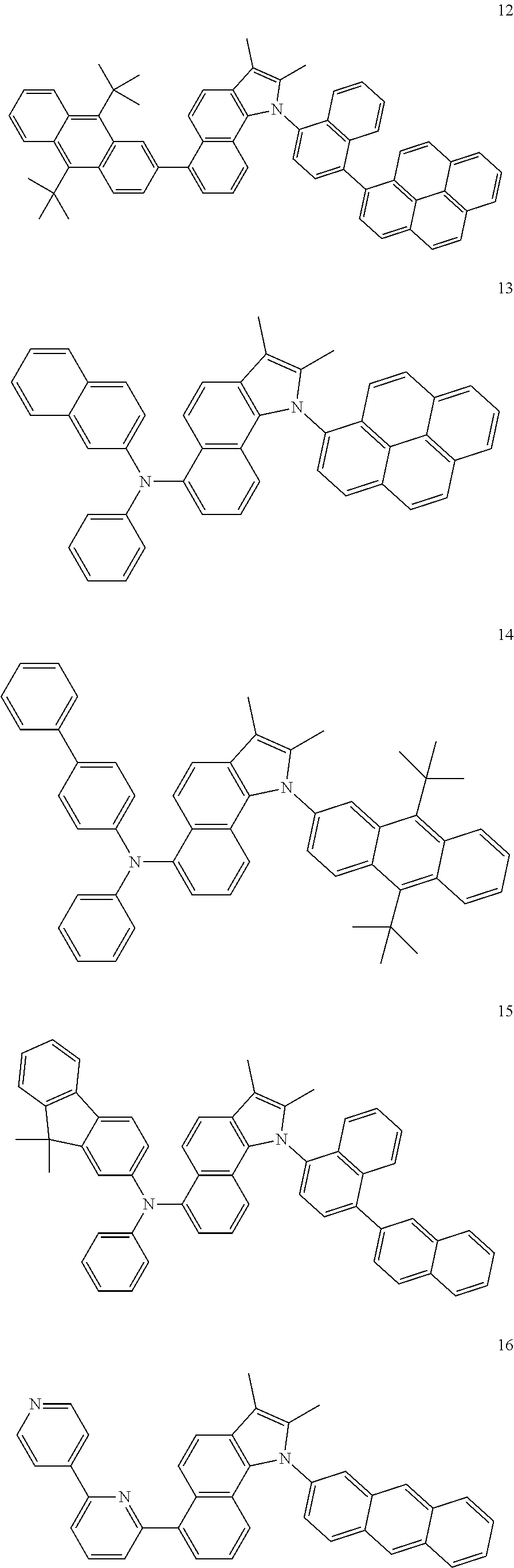
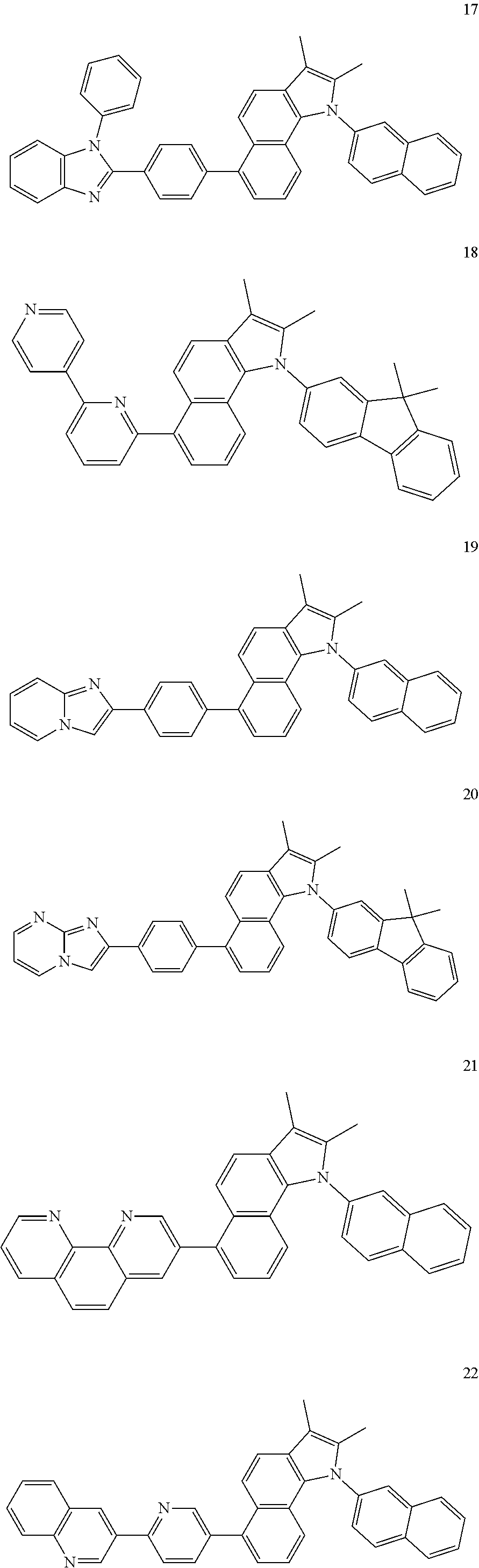
The heterocyclic compound may include one of the compounds below:
Figure US09163004-20151020-C00003
According to another aspect of the present embodiments, there is provided an organic light-emitting device including: a first electrode; a second electrode; and an organic layer between the first electrode and the second electrode, wherein the organic layer includes at least one layer including the above heterocyclic compound.
The organic layer may include an electron injection layer or an electron transport layer.
The organic layer may include a single layer having both an electron injection function and an electron transport function.
The organic layer may include an emission layer.
The organic layer may include an emission layer, and the heterocylic compound may be used as a host for a fluorescent or phosphorescent device.
The organic layer may include an emission layer, and the heterocylic compound may be used as a fluorescent dopant.
The emission layer, the electron injection layer, or the electron transport layer of the organic light-emitting device may include the heterocyclic compound, wherein the emission layer may include an anthracene compound, or a styryl compound.
The electron injection layer or the electron transport layer of the organic light-emitting device may include the heterocyclic compound, and a red emission layer, a green emission layer, a blue emission layer, or a white emission layer may include a phosphorescent compound.
The organic layer may include at least one layer selected from the group consisting of a hole injection layer, a hole transport layer, an electron blocking layer, an emission layer, a hole blocking layer, an electron transport layer, and an electron injection layer.
The organic light-emitting device may have a first electrode/hole injection layer/emission layer/second electrode structure, a first electrode/hole injection layer/hole transport layer/emission layer/electron transport layer/second electrode structure, or a first electrode/hole injection layer/hole transport layer/emission layer/electron transport structure layer/electron injection layer/second electrode structure.
According to another aspect of the present embodiments, there is provided a flat panel display device including the above organic light-emitting device, wherein the first electrode of the organic light-emitting device is electrically connected to a source electrode or a drain electrode of a thin-film transistor.
According to another aspect of the present embodiments, there is provided an organic light-emitting device including: a first electrode; a second electrode; and an organic layer between the first electrode and the second electrode, wherein the organic layer includes at least one layer including the above heterocyclic compound, the at least one layer being formed using a wet process.
BRIEF DESCRIPTION OF THE DRAWINGS
The above and other features and advantages of the present embodiments will become more apparent by describing in detail example embodiments thereof with reference to the attached drawing in which:
FIG. 1 is a diagram of the structure of an organic light-emitting device according to an embodiment.
DETAILED DESCRIPTION
The present embodiments will now be described more fully with reference to the accompanying drawings, in which example embodiments are shown.
A heterocyclic compound according to an embodiment is represented by Formula 1 below:
Figure US09163004-20151020-C00004
wherein R1 through R9 are each independently a hydrogen atom, a heavy hydrogen atom (deuterium or tritium), a substituted or unsubstituted C1-C50 alkyl group, a substituted or unsubstituted C3-C50 cycloalkyl group, a substituted or unsubstituted C1-C50 alkoxy group, a substituted or unsubstituted C5-C50 aryloxy group, a substituted or unsubstituted C5-C50 arylthio group, a substituted or unsubstituted C5-C60 aryl group, a substituted amino group with a R5-R60 aryl group, a substituted or unsubstituted C3-C60 heteroaryl group, a substituted or unsubstituted C6-C60 condensed polycyclic group, a halogen atom, a cyano group, a nitro group, a hydroxyl group, or a carboxyl group, wherein two vicinal substituents among R1 through R9 are linked to each other to form an aromatic ring.
Examples of materials for forming an emission layer or an electron transport layer, which constitute an organic light-emitting device, include, but are not limited to, Alq3, 2,2′,2″-(1,3,5-phenylene)tris-(1-phenyl)-1H-benzimidazol (TPBI), 2-Biphenyl-4-yl-5-(4-tert-butyl-phenyl)-[1,3,4]oxadiazole (PBD), perfluorinated chemical (PF-6P), and 2,5-bis(6′-(2′,2″-bipyridyl))-1,1-dimethyl-3,4-diphenylsiylol (PyPySPyPy).
An organic light-emitting device manufactured using the heterocyclic compound of Formula 1, in which a phenenthrene group and an indole group are fused, has excellent durability when stored or operated. In addition, due to the inclusion of a substituent such as a fluorene group or a naphthyl group, molecular layers formed as thin films may be maintained in good condition, thereby improving the characteristics of the organic light-emitting device.
Substituents in the heterocyclic compound of Formula 1 will now be described in detail.
In Formula 1 above, R1, R2, R3 or R6 may be an aryl group. The aryl group may be substituted with a substituent described later in conjunction with the C1-C50 alkyl group.
R6 may be an unsubstituted monocyclic to tetracyclic aryl group selected from the group consisting of a phenyl group, a naphthyl group, a biphenyl group, a terphenyl group, an anthracenyl group, a fluorenyl group, a carbazolyl group, and a pyrenyl group; an unsubstituted C3-C60 heteroaryl group; an unsubstituted C5-C50 arylamine group; a substituted monocyclic to tetracyclic aryl group selected from the group consisting of a phenyl group, a naphthyl group, a biphenyl group, a terphenyl group, an anthracenyl group, a fluorenyl group, a carbazolyl group, and a pyrenyl group which are optionally substituted with a C1-C5 alkyl group, a C1-C5 alkoxy group, a cyano group, an amine group, a phenoxy group, a phenyl group, a halogen group or a C3-C10 heteroaryl group; a substituted C3-C60 heteroaryl group which is optionally substituted with a C1-C5 alkyl group, a C1-C5 alkoxy group, a cyano group, an amine group, a phenoxy group, a phenyl group or a halogen group; or a substituted C5-C50 arylamine group which is substututed with a C1-C5 alkyl group, a C1-C5 alkoxy group, a cyano group, an amine group, a phenoxy group, a phenyl group or a halogen group.
R1 may be an unsubstituted monocyclic to tetracyclic aryl group selected from the group consisting of a phenyl group, a naphthyl group, a biphenyl group, a terphenyl group, an anthracenyl group, a fluorenyl group, a carbazolyl group, and a pyrenyl group; an unsubstituted C3-C60 heteroaryl group; a substituted monocyclic to tetracyclic aryl group selected from the group consisting of a phenyl group, a naphthyl group, a biphenyl group, a terphenyl group, an anthracenyl group, a fluorenyl group, a carbazolyl group, and a pyrenyl group which are optionally substituted with a C1-C5 alkyl group, a C1-C5 alkoxy group, a cyano group, an amine group, a phenoxy group, a phenyl group or a halogen group; or a substituted C3-C60 heteroaryl group which is substituted with a C1-C5 alkyl group, a C1-C5 alkoxy group, a cyano group, an amine group, a phenoxy group, a phenyl group, a halogen group, or a C3-C10 heteroaryl group.
R2 and R3 may be each independently a methyl group or a phenyl group.
Hereinafter, substituents described with reference to Formula 1 will now be described in detail. In this regard, the numbers of carbons in substituents are presented only for illustrative purposes and do not limit the characteristics of the substituents.
The unsubstituted C1-C50 alkyl group used herein may be linear or branched. Examples of the unsubstituted C1-C50 alkyl group include, but are not limited to, a methyl group, an ethyl group, a propyl group, an isobutyl group, a sec-butyl group, a pentyl group, an iso-amyl group, a hexyl group, a heptyl group, an octyl group, a nonanyl group, and a dodecyl group. At least one hydrogen atom of the alkyl group may be substituted with a heavy hydrogen atom, a halogen atom, a hydroxyl group, a nitro group, a cyano group, an amino group, an amidino group, hydrazine, hydrazone, a carboxyl group or a salt thereof, a sulfonic acid group or a salt thereof, a phosphoric acid group or a salt thereof, a C1-C10 alkyl group, a C1-C10 alkoxy group, a C2-C10 alkenyl group, a C2-C10 alkynyl group, a C6-C16 aryl group, or a C3-C16 heteroaryl group.
The unsubstituted C3-C50 cycloalkyl group used herein refers to a C3-C50 cyclic alkyl group wherein at least one hydrogen atom in the cycloalkyl group may be substituted with a substituent such as those described above in connection with the C1-C50 alkyl group.
The unsubstituted C1-C50 alkoxy group used herein is a group having a structure of —OA wherein A is an unsubstituted C1-C50 alkyl group as described above. Examples of the unsubstituted C1-C50 alkoxy group include, but are not limited to, a methoxy group, an ethoxy group, a propoxy group, an isopropyloxy group, a butoxy group, and a pentoxy group. At least one hydrogen atom of the alkoxy group may be substituted with a substituent such as those described above in conjunction with the alkyl group.
The unsubstituted C5-C60 aryl group used herein refers to a carbocyclic aromatic system containing at least one ring. At least two rings may be fused to each other or linked to each other by a single bond. The term ‘aryl’ refers to an aromatic system, such as phenyl, naphthyl, or anthracenyl. At least one hydrogen atom in the aryl group may be substituted with substituent such as those described above in conjunction with the C1-C50 alkyl group.
Examples of the substituted or unsubstituted C5-C60 aryl group include, but are not limited to, a phenyl group, a C1-C10 alkylphenyl group (for example, an ethylphenyl group), a halophenyl group (for example, o-, m-, and p-fluorophenyl group, a dichlorophenyl group), a cyanophenyl group, dicyanophenyl group, a trifluoromethoxyphenyl group, a biphenyl group, a halobiphenyl group, a cyanobiphenyl group, a C1-C10 alkyl biphenyl group, a C1-C10 alkoxybiphenyl group, an o-, m-, and p-tolyl group, an o-, m-, and p-cumenyl group, a mesityl group, a phenoxyphenyl group, a (α,α-dimethylbenzene)phenyl group, a (N,N′-dimethyl)aminophenyl group, a (N,N′-diphenyl)aminophenyl group, a pentalenyl group, an indenyl group, a naphthyl group, a halonaphthyl group (for example, a fluoronaphthyl group), a C1-C10 alkylnaphthyl group (for example, a methylnaphthyl group), a C1-C10 alkoxynaphthyl group (for example, a methoxynaphthyl group), a cyanonaphthyl group, an anthracenyl group, an azulenyl group, a heptalenyl group, an acenaphthylenyl group, a phenalenyl group, a fluorenyl group, an anthraquinolyl group, a methylanthryl group, a phenanthryl group, a triphenylene group, a pyrenyl group, a chrycenyl group, an ethyl-chrysenyl group, a picenyl group, a perylenyl group, a chloroperylenyl group, a pentaphenyl group, a pentacenyl group, a tetraphenylenyl group, a hexaphenyl group, a hexacenyl group, a rubicenyl group, a coronelyl group, a trinaphthylenyl group, a heptaphenyl group, a heptacenyl group, a pyranthrenyl group, and an ovalenyl group.
The unsubstituted C3-C60 heteroaryl group used herein includes one, two or three hetero atoms selected from N, O, P and S. At least two rings may be fused to each other or linked to each other by a single bond. Examples of the unsubstituted C3-C60 heteroaryl group may include a pyrazolyl group, an imidazolyl group, an oxazolyl group, a thiazolyl group, a triazolyl group, a tetrazolyl group, an oxadiazolyl group, a pyridinyl group, a pyridazinyl group, a pyrimidinyl group, a triazinyl group, a carbazolyl group, an indolyl group, a quinolinyl group, and an isoquinolinyl group. At least one hydrogen atom in the heteroaryl group may be substituted with a substituent such as those described above in conjunction with the C1-C50 alkyl group.
The unsubstituted C5-C50 aryloxy group is represented by —OA1 wherein A1 may be a C5-C50 aryl group. Examples of the aryloxy group may include a phenoxy group but are not limited to. At least one hydrogen atom in the aryloxy group may be substituted with a substituent such as those described above in conjunction with the C1-C50 alkyl group.
The unsubstituted C5-C50 arylthio group is represented by —SA1 where A1 may be a C5-C50 aryl group. Examples of the arylthio group include, but are not limited to, a benzenethio group, and a naphthylthio group. In the arylthio group, at least one hydrogen atom may be substituted with a substituent such as those described above in conjunction with the unsubstituted C1-C50 alkyl group.
The unsubstituted C6-C60 condensed polycyclic group used herein refers to a substituent including at least two rings wherein at least one aromatic ring and/or at least one non-aromatic ring are fused to each other.
The C5-C50 arylamine group refers to an amine group with a C5-C50 aryl group as a substituent.
Examples of the heterocyclic compound represented by Formula 1 may include Compounds 1 through 55 represented by the following formulae. However, the compounds represented by Formula 1 are not limited thereto.
Figure US09163004-20151020-C00005
Figure US09163004-20151020-C00006
Figure US09163004-20151020-C00007
Figure US09163004-20151020-C00008
Figure US09163004-20151020-C00009
Figure US09163004-20151020-C00010
Figure US09163004-20151020-C00011
Figure US09163004-20151020-C00012
Figure US09163004-20151020-C00013
Figure US09163004-20151020-C00014
Figure US09163004-20151020-C00015
Figure US09163004-20151020-C00016
Figure US09163004-20151020-C00017
An organic light-emitting device according to an embodiment includes a first electrode, a second electrode, and an organic layer disposed between the first electrode and the second electrode, the organic layer including the heterocylic compound of Formula 1 described above.
The organic layer, which includes the heterocyclic compound of Formula 1, may be an electron injection layer, an electron transport layer, or a single layer having both the abilities to inject and transport electrons. Alternatively, the organic layer including the heterocyclic compound of Formula 1 may be an emission layer. When the organic layer including the heterocyclic compound of Formula 1 is an emission layer, the heterocyclic compound of Formula 1 may be used as a host for a fluorescent or phosphorescent device or a fluorescent dopant.
In the organic light-emitting device, when the emission layer, the electron injection layer or the electron transport layer includes the heterocyclic compound of Formula 1, the emission layer may include an anthracene compound, an arylamine compound or a styryl compound, wherein the anthracene compound, the arylamine compound or the styryl compound may be unsubstituted or substituted with a substituent described above in conjunction with the C1-C50 alkyl group.
In the organic light-emitting device, when the electron injection layer or the electron transport layer includes the heterocyclic compound of Formula 1, a red emission layer, a green emission layer, a blue emission layer or a white emission layer may include a phosphorescent compound.
In some embodiments, the organic layer of the organic light-emitting device may further include, but is not limited to, a hole injection layer, a hole transport layer, a functional layer having both hole injection and transport functions, an emission layer, a hole blocking layer, an electron transport layer, an electron injection layer, of a combination of at least two of these layers. At least one of the hole injection layer, the hole transport layer, and the functional layer having both hole injection and transport functions, may further include, in addition to the heterocylic compound of Formula 1 and widely-known hole injection and transport materials, a charge-generating material for improving conductivity of the layer.
The charge-generating material may include, for example, a p-dopant. Nonlimiting examples of the p-dopant include quinine derivatives, including tetracyanoquinondimethane (TCNQ) and 2,3,5,6-tetrafluoro-tetracyano-1,4-benzoquinonedimethane (F4TCNQ); metal oxides, including tungsten oxide and molybdenium oxide; and cyano group-containing compounds, including a compound represented by Formula 100 below.
Figure US09163004-20151020-C00018
In some embodiments, when the hole injection layer, the hole transport layer, or the functional layer having both hole injection and transport functions further includes the charge-generating material, the charge-generating material may be uniformly or nonuniformly distributed in the layer.
In one embodiment, the electron transport layer of the organic light-emitting device may include an electron transporting organic compound and a metal-containing material. Nonlimiting examples of the electron transporting organic compound include ADN(9,10-di(naphthalene-2-yl)anthracene); and anthracene-based compounds, including a compound of Formula 101 and a compound of Formula 102 below.
Figure US09163004-20151020-C00019
The metal-containing material may include a Li complex. Nonlimiting examples of the Li complex include lithium quinolate (LiQ) and a compound of Foimula 103 below.
Figure US09163004-20151020-C00020
The first electrode may be an anode, and the second electrode may be a cathode, but the reverse is also possible.
In the organic light-emitting described above, the organic layer may further include at least one layer selected from the group consisting of a hole injection layer, a hole transport layer, an electron blocking layer, an emission layer, a hole blocking layer, an electron transport layer and an electron injection layer, if required.
For example, the organic light-emitting device may have a first electrode/hole injection layer/emission layer/second electrode structure, a first electrode/hole injection layer/hole transport layer/emission layer/electron transport layer/second electrode structure, or a first electrode/hole injection layer/hole transport layer/emission layer/electron transport layer/electron injection layer/second electrode structure. Alternatively, the organic light-emitting device may have a first electrode/single layer having both hole injection and hole transport capabilities/emission layer/electron transport layer/second electrode structure, or a first electrode/single layer having both hole injection and hole transport capabilities/emission layer/electron transport layer/electron injection layer/second electrode structure.
According to some embodiments, the organic light-emitting device may be either a top-emission organic light-emitting device or a bottom-emission organic light-emitting device.
Hereinafter, a method of manufacturing an organic light-emitting device according to an embodiment will be described with reference to FIG. 1. FIG. 1 illustrates the structure of an organic light-emitting device according to an embodiment. Referring to FIG. 1, the organic light-emitting device according to the present embodiment includes a substrate (not shown), a first electrode (anode), a hole injection layer (HIL), a hole transport layer (HTL), an emission layer (EML), an electron transport layer (ETL), an electron injection layer (EIL), and a second electrode (cathode).
First, the first electrode is formed on the substrate by using a deposition or sputtering method. The first electrode may comprise a first electrode material having a high work function. The first electrode may constitute an anode or a cathode. The substrate may be a substrate conventionally used in organic light-emitting devices, and may include, for example, a glass substrate or a transparent plastic substrate with excellent mechanical strength, thermal stability, transparency, surface smoothness, ease of handling, and water resistance. Examples of the first electrode material include materials, such as indium tin oxide (ITO), indium zinc oxide (IZO), tin oxide (SnO2), zinc oxide (ZnO), aluminum (Al), silver (Ag), and magnesium (Mg), which have excellent conductivity. The first electrode may be formed as a transparent or reflective electrode.
Next, the HIL may be formed on the first electrode using various methods, for example, vacuum deposition, spin coating, casting, Langmuir-Blodgett (LB) deposition, or the like.
When the HIL is formed using vacuum deposition, the deposition conditions may vary according to the material used to form the HIL, and the structure and thermal characteristics of the HIL. For example, the deposition conditions may include a deposition temperature of about 100 to about 500° C., a vacuum pressure of about 10−8 to about 10−3torr, and a deposition rate of about 0.01 to about 100 Å/sec.
When the HIL is formed using spin coating, coating conditions may vary according to the material used to faun the HIL, and the structure and thermal properties of the HIL. For example, the coating conditions may include a coating rate of about 2000 rpm to about 5000 rpm, and a thermal treatment temperature of about 80° C. to about 200° C., wherein the thermal treatment serves to remove the solvent after coating.
The HIL may comprise any material that is commonly used to form a HIL. Examples of the material that can be used to form the HIL include a phthalocyanine compound such as copper phthalocyanine, 4,4′,4″-tris(3-methylphenylphenylamino) triphenylamine (m-MTDATA), N,N′-di(1-naphthyl)-N,N′-diphenylbenzidine (NPB), TDATA, 2-TNATA, polyaniline/dodecylbenzenesulfonic acid (Pani/DBSA), poly(3,4-ethylenedioxythiophene)/poly(4-styrenesulfonate) (PEDOT/PSS), polyaniline/camphor sulfonic acid (Pani/CSA), and polyaniline)/poly(4-styrenesulfonate (PANI/PSS), but are not limited thereto.
Figure US09163004-20151020-C00021
The HIL may have a thickness of about 100 Å to about 10000 Å. When the thickness of the HIL is within these ranges, the HIL may have good hole injection characteristics without an increase in driving voltage.
Next, the HTL may be formed on the HIL using various methods, for example, vacuum deposition, spin coating, casting, LB deposition, or the like. When the HTL is formed using vacuum deposition or spin coating, the deposition or coating conditions may be similar to those used to form the HIL, though the deposition or coating conditions may vary according to the material that is used to form the HTL.
Alternatively, known HTL materials may be used. Examples of such HTL materials include, but are not limited to, carbazole derivatives such as N-phenylcarbazole or polyvinylcarbazole, and amine derivatives having an aromatic condensed ring, such as NPB, N,N′-bis(3-methylphenyl)-N,N′-diphenyl-[1,1-biphenyl]-4,4′-diamine (TPD), or the like. For example, TCTA may not only transport holes but also inhibit excitons from being diffused from the EML.
Figure US09163004-20151020-C00022
The HTL may have a thickness of about 50 Å to about 1000 Å, for example, a thickness of about 100 Å to about 600 Å. When the thickness of the HTL is within these ranges, the HTL may have good hole transport characteristics without a substantial increase in driving voltage.
Next, the EML may be formed on the HTL using various methods, for example, vacuum deposition, spin coating, casting, LB deposition, or the like. When the EML is formed using vacuum deposition or spin coating, the deposition or coating conditions may be similar to those used to form the HIL, though the deposition or coating conditions may vary according to the material that is used to form the EML.
The EML may include the heterocyclic compound of Formula 1 described above. For example, the heterocyclic compound of Formula 1 may be used as a host or a dopant. The EML may be formed using a variety of light-emitting materials, in addition to the heterocyclic compound of Formula 1. Alternatively, the EML may also be formed using a host and a dopant. Dopants that may be used to form the EML may include either a fluorescent dopant or a phosphorescent dopant.
Examples of the host may include, but are not limited to, Alq3, 4,4′-N,N′-dicarbazole-biphenyl (CPB), 9,10-di(naphthalen-2-yl)anthracene (ADN), and distyrylarylene (DSA).
Examples of red dopants include, but are not limited to, platinum(II) octaethylporphyrin (PtOEP), Ir(piq)3, Btp2Ir(acac), and DCJTB (4-(dicyanomethylene)-2-t-butyl-6(1,1,7,7-tetramethyljulolidyl-9-enyl)-4H-pyran).
Figure US09163004-20151020-C00023
Examples of green dopants include, but are not limited to, Ir(ppy)3 (where “ppy” denotes phenylpyridine), Ir(ppy)2(acac), Ir(mpyp)3, and C545T.
Figure US09163004-20151020-C00024
Examples of blue dopants include, but are not limited to, F2Irpic, (F2ppy)2Ir(tmd), Ir(dfppz)3, ter-fluorene, 4,4′-bis(4-diphenylaminostyryl)biphenyl (DPAVBi), and 2,5,8,11-tetra-t-butyl pherylene (TBP).
Figure US09163004-20151020-C00025
The amount of the dopant may be in a range of about 0.1 to about 20 parts by weight, or about 0.5 to about 12 parts by weight, based on 100 parts by weight of the EML material (which is equivalent to the total weight of the host and the dopant). When the amount of the dopant is within these ranges, concentration quenching may be substantially prevented.
The EML may have a thickness of about 100 Å to about 1,000 Å, for example, about 200 Å to about 600 Å. When the thickness of the EML is within these ranges, the EML may have good light-emitting characteristics without a substantial increase in driving voltage.
When the EML includes a phosphorescent dopant, a hole blocking layer (HBL, not shown in FIG. 1) may be formed on the EML in order to prevent diffusion of triplet excitons or holes into the ETL. In this case, the HBL may comprise any material commonly used to form a HBL, without limitation. Examples of such HBL materials include, but are not limited to, oxadiazole derivatives, triazole derivatives, phenathroline derivatives, BAlq, and BCP.
The HBL may have a thickness of about 50 Å to about 1,000 Å, for example, about 100 Å to about 300 Å. When the thickness of the HBL is within these ranges, the HBL may have good hole blocking characteristics without a substantial increase in driving voltage.
Next, the ETL is formed on the EML (or HBL) using various methods, for example, vacuum deposition, spin coating, casting, or the like. When the ETL is formed using vacuum deposition or spin coating, the deposition or coating conditions may be similar to those used to form the HIL, though the deposition or coating conditions may vary according to the material used to form the ETL.
The ETL material may include the heterocyclic compound of Formula 1 described above. Alternatively, the ETL may comprise any known material. Examples of the ETL material include, but are not limited to, quinoline derivatives, such as tris(8-quinolinolate)aluminum (Alq3), TAZ, and BAlq.
Figure US09163004-20151020-C00026
The ETL may have a thickness of about 100 Å to about 1,000 Å, for example, about 100 Å to about 500 Å. When the thickness of the ETL is within these ranges, the ETL may have good electron transport characteristics without a substantial increase in driving voltage.
In addition, the EIL, which facilitates injection of electrons from the cathode, may be formed on the ETL.
The EIL may include the heterocyclic compound of Formula 1 described above. Alternatively, EIL materials, such as LiF, NaCl, CsF, Li2O, or BaO, may be used to form the EIL. The deposition or coating conditions for forming the EIL may be similar to those applied to form the HIL, though the deposition and coating conditions may vary according to the material that is used to form the EIL.
The EIL may have a thickness of about 1 Å to 100 Å, for example, about 5 Å to about 90 Å. When the thickness of the EIL is within these ranges, the EIL may have good electron injection characteristics without a substantial increase in driving voltage.
Finally, the second electrode may be formed on the EIL by using, for example, vacuum deposition, sputtering, or the like. The second electrode may be a cathode or an anode. The material for forming the second electrode may include a metal, an alloy, or an electrically conductive compound, which are materials having a low work function, or a mixture thereof Examples of such materials include, but are not limited to, lithium (Li), magnesium (Mg), aluminum (Al), aluminum-lithium (Al—Li), calcium (Ca), magnesium-indium (Mg—In), and magnesium-silver (Mg—Ag). In addition, in order to manufacture a top-emission organic light-emitting device, a transparent cathode formed of a transparent material such as ITO or IZO may be used as the second electrode.
The organic light-emitting device according to some embodiments may be included in various types of flat panel display devices, such as in a passive matrix organic light-emitting display device or in an active matrix organic light-emitting display device. In particular, when the organic light-emitting device is included in an active matrix organic light-emitting display device including a thin-film transistor, the first electrode on the substrate may function as a pixel electrode, electrically connected to a source electrode or a drain electrode of the thin-film transistor. Moreover, the organic light-emitting device may also be included in flat panel display devices having double-sided screens.
At least one layer of the organic light-emitting device according to the embodiment described above may comprise the heterocyclic compound of Formula 1 by using a deposition method or a wet method of coating a solution of the heterocylic compound of Formula 1.
Hereinafter, synthesis examples of Compounds 16, 25, 27, and 40 and examples will be described in detail. However, these examples are for illustrative purposes only, and are not intended to limit the scope of the present embodiments.
Synthesis Examples
Figure US09163004-20151020-C00027
Synthesis of Intermediate C-1
300 mL of toluene was added to a mixture of 28.6 g (100 mmole) of 1,5-dibromonaphthalene, 11.7 g (60 mmole) of benzophenone hydrazone, 330 mg (3 mol %) of Pd(OAc)2, and 7.3 g (75.0 mmole) of KOt-Bu and then heated at 90° C. in a nitrogen atmosphere for 4 hours. The reaction mixture was cooled to room temperature, and 100 mL of water was further added to the reaction mixture and was extracted twice with 500 mL of methylene chloride. The organic phase was dried, filtered, concentrated, and then separated using column chromatography to obtain 16.8 g of Compound C-1 in yellow solid form with a yield of 84%. The structure of Compound C-1 was identified using high-resolution mass spectrometry (HR-MS). (calc.; 400.0575, found; 400.0561)
Synthesis of Intermediate C-2
100 mL of toluene and 50 mL of ethanol were added to a mixture of 20.1 g (50 mmole) of Compound C-1, 38.0 g (200 mmole) of pTSA.H2O and 50 mL of methyl ethyl ketone and then heated at 90° C. for 36 hours. The reaction mixture was cooled to room temperature, and 100 mL of water was further added to the reaction mixture and was extracted twice with 200 mL of methylene chloride. The organic phase was dried, filtered, concentrated, and then separated by column chromatography to obtain 9.3 g of Compound C-2 in light-green solid form with a yield of 68%. The structure of Compound C-2 was identified using high-resolution mass spectrometry (HR-MS). (calc.; 273.0153, found; 273.0148)
Synthesis of Intermediate C-3
30 mL of water and 100 mL of tetrahydrofuran (THF) were added to a mixture of 8.3 g (30 mmole) of Compound C-2, 6.6 g (33 mmole) of bipyridyl boronic acid, 1.7 g (5 mol %) of Pd(PPh3)4, and 4.8 g (120 mmole) of NaOH and then heated at 70° C. in a nitrogen atmosphere for 12 hours. The reaction mixture was cooled to room temperature, and 50 mL of water was further added to the reaction mixture and was extracted twice with 300 mL of methylene chloride. The organic phase was dried, filtered, concentrated, and then separated using column chromatography to obtain 6.07 g of Compound C-3 in pale-yellow solid form with a yield of 58%. The structure of Compound C-3 was identified using high-resolution mass spectrometry (HR-MS). (calc.; 349.1579, found; 349.1568)
Synthesis of Compound 16
100 mL of toluene was added to a mixture of 13.3 g (30.0 mmole) of Compound C-3, 8.07 g (39.0 mmole) of a 2-bromonaphthalene, 4.3 g (45.0 mmole) of NaOtBu, 1.4 g (1.5 mmole) of Pd2(dba)3, and 0.30 g (1.5 mmole) of PtBu3 and then heated at 90° C. in a nitrogen atmosphere for 6 hours. The reaction mixture was cooled to room temperature, and 30 mL of water was further added to the reaction mixture and was extracted twice with 200 mL of methylene chloride. The organic phase was dried, filtered, concentrated, and then separated using column chromatography to obtain 9.2 g of Compound 16 in light-yellow solid form with a yield of 65%. The structure of Compound 16 was identified using nuclear magnetic resonance (NMR) spectroscopy and HR-MS.
1H-NMR (CDCl3, 400 MHz) δ (ppm); 8.12-8.75 (m, 5H), 6.89-7.78 (m, 19H), 2.44 (s, 3H), 2.41 (s, 3H). 13-C NMR (CDCl3, 100 MHz) δ (ppm); 162.2, 160.4, 158.6, 138.8, 138.4, 138.1, 136.7, 134.8, 133.8, 133.0, 132.2, 132.0, 130.7, 129.6, 129.0, 128,2, 127.2, 126.5, 126.2, 124.3, 122.6, 122.0 119.6, 119.2, 118.5, 118.0, 116.7, 116.4, 116.0, 114.2, 112,1, 12.1, 8.1.
HRMS (calc.; 475.2048, found; 475.2040)
Figure US09163004-20151020-C00028
Synthesis of Compound 25
10.0 g of Compound 25 in light-yellow solid was synthesized with a yield of 50% by using 13.3 g (30 mmole) of Compound C-3 and 13.6 g (39 mmole) of 2-(4-bromo-phenyl)-1-phenyl-1H-benzoimidazole in the same manner as used in the synthesis of Compound 16. The structure of Compound 25 was identified using nuclear magnetic resonance (NMR) spectroscopy and HR-MS.
1H-NMR (CDCl3, 400 MHz) δ (ppm); 8.22-8.65 (m, 5H), 6.99-7.65 (m, 20H), 2.40 (s, 3H), 2.31 (s, 3H). 13-C NMR (CDCl3, 100 MHz) δ (ppm); 164.3, 162.3, 159.7, 140.8, 140.4, 139.4, 136.7, 135.8, 134.8, 133.7, 132.6, 132.0, 130.3, 129.1, 128.1, 127.2, 126.6, 126.1, 124.8, 122.1, 119.8, 119.2, 118.5, 118.0, 116.7, 116.4, 116.0, 114.2, 112,1, 15.1, 10.6.
HRMS (calc.; 617.2579, found; 617.2571)
Figure US09163004-20151020-C00029
Synthesis of Compound 27
7.9 g of Compound 27 in light-yellow solid was synthesized with a yield of 43% by using 13.3 g (30 mmole) of Compound C-3 and 9.12 g (39 mmole) of 6-bromo bipyridyl in the same manner as used in the synthesis of Compound 16. The structure of Compound 27 was identified using nuclear magnetic resonance (NMR) spectroscopy and HR-MS.
1H-NMR (CDCl3, 400 MHz) δ (ppm); 8.02-8.43 (m, 4H), 7.02-7.85 (m, 15H), 2.42 (s, 3H), 2.32 (s, 3H). 13-C NMR (CDCl3, 100 MHz) δ (ppm); 160.3, 159.3, 158.3, 150.8, 146.4, 139.8, 138.7, 137.8, 137.1, 136.5, 136.0, 134.3, 131.6, 131.0, 130.3, 129.1, 128.1, 127.4, 126.6, 126.1, 125.4, 124.8, 122.1, 119.8, 119.2, 118.5, 116.7, 116.4, 116.0, 114.2, 14.1, 9.5.
HRMS (calc.; 503.2110, found; 503.2101)
Figure US09163004-20151020-C00030
Synthesis of Intermediate C-4
12.3 g of Compound C-4 in pale-yellow solid form was synthesized with a yield of 62% in the same manner as used in the synthesis of Compound C-2, except that 19.6 g (100 mmole) of benzyl phenyl ketone was used, instead of methyethylketone. The structure of Compound C-4 was identified using high-resolution mass spectrometry (HR-MS). (calc.; 397.0466, found; 397.0456)
Synthesis of Intermediate C-5
10.6 g of Compound C-5 in pale-yellow solid was synthesized with a yield of 75% by using 11.9 g (30 mmole) of Compound C-4 and 6.6 g (33 mmole) of bipyridyl boronic acid in the same manner as used in the synthesis of Compound C-3. The structure of Compound C-5 was identified using high-resolution mass spectrometry (HR-MS). (calc.; 473.1892, found; 473.1883)
Synthesis of Compound 40
8.8 g of Compound 40 in light-yellow solid was synthesized with a yield of 62% by using 13.0 g (30 mmole) of Compound C-5 and 6.8 g (39 mmole) of bromonaphthalene in the same manner as used in the synthesis of Compound 16. The structure of Compound 40 was identified using nuclear magnetic resonance (NMR) spectroscopy and HR-MS.
1H-NMR (CDCl3, 400 MHz) δ (ppm); 8.23-8.53 (m, 5H), 7.06-7.86 (m, 24H). 13-C NMR (CDCl3, 100 MHz) δ (ppm); 158.3, 153.3, 152.3, 139.7, 138.5, 137.5, 137.1, 136.5, 136.2, 135.3, 134.2, 133.5, 132.1, 131.6, 131.0, 130.3, 129.1, 128.1, 127.8, 127.4, 126.6, 126.1, 125.4, 124.8, 122.1, 121.7, 121.0, 119.8, 119.2, 118.5, 116.7, 116.4, 116.0, 114.2.
HRMS (calc.; 599.2361, found; 599.2352)
Example 1
An anode was prepared by cutting a Corning 15 Ωcm2 (1200 Å) ITO glass substrate to a size of 50 mm×50 mm×0.7 mm, ultrasonically cleaning the glass substrate using isopropyl alcohol and pure water for 5 minutes each, and then irradiating UV light for 30 minutes and exposing to ozone to clean. Then, the anode was mounted in a vacuum deposition apparatus.
Then, 2-TNATA (which is an HIL material) was vacuum-deposited on the glass substrate to form a HIL having a thickness of about 600 Å. Then, 4,4′-bis[N-(1-naphthyl)-N-phenylamino]biphenyl (NPB) (which is a hole transporting compound) was vacuum-deposited on the HIL to form a HTL having a thickness of about 300 Å.
Then, a green fluorescent host (Alq3) and a green fluorescent dopant (C545T) were simultaneously deposited in a weight ratio of 98:2 on the HTL, to form an EML having a thickness of about 300 Å.
Then, Compound 16 was deposited on the EML to form an ETL having a thickness of about 300 Å, and then LiF (which is halogenated alkali metal) was deposited on the ETL to form an EIL having a thickness of about 10 Å. Then, Al was vacuum-deposited on the EIL to a thickness of about 3000 Å to form a LiF/Al electrode (cathode), thereby completing the manufacture of an organic light-emitting device.
The organic light-emitting device had a driving voltage of 5.97 V at a current density of 50 mA/cm2, a high luminosity of 8,454 cd/m2, color coordinates of (0.311, 0.642), and a luminescent efficiency of 16.91 cd/A.
Example 2
An organic light-emitting device was manufactured in the same manner as in Example 1, except that Compound 25 was used instead of Compound 16 to form the ETL.
The organic light-emitting device had a driving voltage of 5.63 V at a current density of 50 mA/cm2, a high luminosity of 8,848 cd/m2, color coordinates of (0.310, 0.642), and a luminescent efficiency of 17.70 cd/A.
Example 3
An organic light-emitting device was manufactured in the same manner as in Example 1, except that Compound 27 was used instead of Compound 16 to form the ETL.
The organic light-emitting device had a driving voltage of 5.82 V at a current density of 50 mA/cm2, a high luminosity of 8,376 cd/m2, color coordinates of (0.309, 0.643), and a luminescent efficiency of 16.75 cd/A.
Example 4
An organic light-emitting device was manufactured in the same manner as in Example 1, except that Compound 40 was used instead of Compound 16 to form the ETL.
The organic light-emitting device had a driving voltage of 5.58 V at a current density of 50 mA/cm2, a high luminosity of 8,651 cd/m2, color coordinates of (0.310, 0.642), and a luminescent efficiency of 17.30 cd/A.
Comparative Example 1
An organic light-emitting device was manufactured in the same manner as in Example 1, except that Alq3 was used, instead of Compound 16, to form the ETL.
Figure US09163004-20151020-C00031
The organic light-emitting device had a driving voltage of 7.45 V at a current density of 50 mA/cm2, a luminosity of 6,102 cd/m2, color coordinates of (0.309, 0.642), which are almost the same as those of Examples 1 through 4, and a luminescent efficiency of 12.2 cd/A.
The organic light-emitting devices including the ETL manufactured using the heterocyclic compounds of Formula 1 according to the present embodiments had a driving voltage that was lower by 1V or greater than devices manufactured using Alq3, and thus had higher efficiency and good I-V-L characteristics. In particular, lifetime characteristics were markedly improved by 100% or greater in the organic light-emitting devices of Examples 1 through 4, as compared to the organic light-emitting device of Comparative Example 1.
TABLE 1
Electron Driving Current Luminescent
Transport Voltage Density Luminance Efficiency Color Half Lifespan (hr
Material (V) (mA/cm2) (cd/m2) (cd/A) Coordinates @100 mA/cm2)
Example 1 Compound 16 5.97 50 8,454 16.91 (0.311, 0.642) 495 hr
Example 2 Compound 25 5.63 50 8,848 17.70 (0.310, 0.642) 550 hr
Example 3 Compound 27 5.82 50 8,376 16.75 (0.309, 0.643) 480 hr
Example 4 Compound 40 5.58 50 8,651 17.30 (0.310, 0.642) 523 hr
Comparative Alq3 7.45 50 6,102 12.2 (0.309, 0.642) 237 hr
Example 1
As described above, novel heterocyclic compounds according to the one or more of the above embodiments have good electrical characteristics, good charge transporting capabilities and good emission characteristics, and may be used to prevent crystallization due to high glass transition temperatures (Tg). The heterocyclic compounds may also be used as electron transporting materials for most color-fluorescent and phosphorescent devices, such as red, green, blue, and white fluorescent and phosphorescent devices, or as red, green, blue or white-light emitting materials. Thus, an organic light-emitting device with high-efficiency, low-driving voltage, high luminance and long lifespan may be manufactured using the heterocylic compounds.
While the present embodiments have been particularly shown and described with reference to example embodiments thereof, it will be understood by those of ordinary skill in the art that various changes in form and details may be made therein without departing from the spirit and scope of the present embodiments as defined by the following claims.

Claims (16)

What is claimed is:
1. A heterocyclic compound represented by Formula 1 below:
Figure US09163004-20151020-C00032
wherein R1 is an unsubstituted monocyclic to tetracyclic aryl group selected from the group consisting of a naphthyl group, a biphenyl group, a terphenyl group, an anthracenyl group, a fluorenyl group, and a pyrenyl group; an unsubstituted C3-C60 heteroaryl group; a substituted monocyclic to tetracyclic aryl group selected from the group consisting of a naphthyl group, a biphenyl group, a terphenyl group, an anthracenyl group, a fluorenyl group, and a pyrenyl group which is substituted with a C1-C5 alkyl group, a C1-C5 alkoxy group, a cyano group, an amine group, a phenoxy group, a phenyl group or a halogen group; and a substituted C3-C60 heteroaryl group which is substituted with a C1-C5 alkyl group, a C1-C5 alkoxy group, a cyano group, an amine group, a phenoxy group, a phenyl group, a halogen group, or a C3-C10 heteroaryl group;
R2 and R3 are each independently a methyl group or a phenyl group;
R6 is an unsubstituted monocyclic to tetracyclic aryl group selected from the group consisting of a phenyl group, a naphthyl group, a biphenyl group, a terphenyl group, an anthracenyl group, a fluorenyl group, and a pyrenyl group; an unsubstituted C3-C60 heteroaryl group; an unsubstituted C5-C50 aryl amine group; a substituted monocyclic to tetracyclic aryl group selected from the group consisting of a phenyl group, a naphthyl group, a biphenyl group, a terphenyl group, an anthracenyl group, a fluorenyl group, and a pyrenyl group which is substituted with a C1-C5 alkyl group, a C1-C5 alkoxy group, a cyano group, an amine group, a phenoxy group, a phenyl group or a halogen group; a substituted C3-C60 heteroaryl group which is substituted with a C1-C5 alkyl group, a C1-C5 alkoxy group, a cyano group, an amine group, a phenoxy group, a phenyl group, a halogen group or a C3-C10 heteroaryl group; or a substituted C5-C50 arylamine group which is substituted with a C1-C5 alkyl group, a C1-C5 alkoxy group, a cyano group, an amine group, a phenoxy group, a phenyl group or a halogen group; and
R4, R5, R7, R8 and R9 is each independently a hydrogen or a deuterium.
2. A compound of one of the compounds below:
Figure US09163004-20151020-C00033
3. A compound of one of the compounds below:
Figure US09163004-20151020-C00034
Figure US09163004-20151020-C00035
Figure US09163004-20151020-C00036
Figure US09163004-20151020-C00037
Figure US09163004-20151020-C00038
Figure US09163004-20151020-C00039
Figure US09163004-20151020-C00040
Figure US09163004-20151020-C00041
Figure US09163004-20151020-C00042
Figure US09163004-20151020-C00043
Figure US09163004-20151020-C00044
Figure US09163004-20151020-C00045
Figure US09163004-20151020-C00046
4. An organic light-emitting device comprising:
a first electrode;
a second electrode; and
an organic layer between the first electrode and the second electrode,
wherein the organic layer comprises a first layer including the heterocyclic compound of claim 1.
5. The organic light-emitting device of claim 4, wherein the first layer comprises an electron injection layer, an electron transport layer, or a single layer having both an electron injection function and an electron transport function.
6. The organic light-emitting device of claim 4, wherein the first layer comprises an emission layer.
7. The organic light-emitting device of claim 4, wherein the first layer comprises an emission layer, and the heterocylic compound is a host or a dopant for a fluorescent or phosphorescent device.
8. The organic light-emitting device of claim 4, wherein the organic layer comprises an emission layer, an electron injection layer or an electron transport layer, and the emission layer comprises an anthracene compound, an aryl amine compound, or a styryl compound.
9. The organic light-emitting device of claim 4, wherein the organic layer comprises an emission layer, an electron injection layer or an electron transport layer, and the emission layer comprises a red emission layer, a green emission layer, a blue emission layer or a white emission layer that comprises a phosphorescent compound.
10. The organic light-emitting device of claim 4, wherein the organic layer further comprises a hole injection layer, a hole transport layer, a functional layer having both hole injection and transport functions, an electron blocking layer, an emission layer, a hole blocking layer, an electron transport layer, an electron injection layer and a combination of at least two of these layers.
11. The organic light-emitting device of claim 10, wherein at least one of the hole injection layer, the hole transport layer, and the functional layer having both hole injection and transport functions further comprises a charge-generating material.
12. The organic light-emitting device of claim 9, wherein the electron transport layer comprises an electron transporting organic material and a metal-containing material.
13. The organic light-emitting device of claim 12, wherein the metal-containing material comprises a lithium complex.
14. The organic light-emitting device of claim 4, having a first electrode/hole injection layer/emission layer/second electrode structure, a first electrode/hole injection layer/hole transport layer/emission layer/electron transport layer/second electrode structure, or a first electrode/hole injection layer/hole transport layer/emission layer/electron transport structure layer/electron injection layer/second electrode structure.
15. The organic light-emitting device of claim 4, wherein the first layer is formed using a wet process.
16. A flat panel display device comprising the organic light-emitting device of claim 4, wherein the first electrode of the organic light-emitting device is electrically connected to a source electrode or a drain electrode of a thin-film transistor.
US13/164,348 2010-06-21 2011-06-20 Organic light-emitting device Active 2033-07-29 US9163004B2 (en)

Applications Claiming Priority (2)

Application Number Priority Date Filing Date Title
KR1020100058622A KR101202349B1 (en) 2010-06-21 2010-06-21 Organic light emitting device
KR10-2010-0058622 2010-06-21

Publications (2)

Publication Number Publication Date
US20110309348A1 US20110309348A1 (en) 2011-12-22
US9163004B2 true US9163004B2 (en) 2015-10-20

Family

ID=45327856

Family Applications (1)

Application Number Title Priority Date Filing Date
US13/164,348 Active 2033-07-29 US9163004B2 (en) 2010-06-21 2011-06-20 Organic light-emitting device

Country Status (3)

Country Link
US (1) US9163004B2 (en)
JP (1) JP5823731B2 (en)
KR (1) KR101202349B1 (en)

Cited By (2)

* Cited by examiner, † Cited by third party
Publication number Priority date Publication date Assignee Title
US20160072072A1 (en) * 2014-09-05 2016-03-10 Samsung Display Co., Ltd. Condensed cyclic compound and organic light-emitting device including the same
US10727416B2 (en) 2016-04-08 2020-07-28 Rohm And Haas Electronic Materials Korea Ltd. Organic electroluminescent compound and organic electroluminescent device comprising the same

Families Citing this family (13)

* Cited by examiner, † Cited by third party
Publication number Priority date Publication date Assignee Title
KR101213495B1 (en) * 2010-06-03 2013-01-14 삼성디스플레이 주식회사 Organic light emitting device
KR101944917B1 (en) 2012-02-08 2019-02-08 삼성디스플레이 주식회사 Heterocyclic compound and organic light-emitting diode including the same
KR102026824B1 (en) * 2012-06-27 2019-10-01 삼성디스플레이 주식회사 Novel fused ring compound and organic light-emitting device including the same
KR102086555B1 (en) * 2013-08-14 2020-03-10 삼성디스플레이 주식회사 Anthracene-based compounds and Organic light emitting device comprising the same
KR102167040B1 (en) * 2013-08-14 2020-10-19 삼성디스플레이 주식회사 Heterocyclic compound and organic light emitting device comprising same
KR102251735B1 (en) 2014-04-14 2021-05-13 삼성디스플레이 주식회사 Material for organic light emitting device, organic light emitting device, and display device including the same
KR101638074B1 (en) * 2014-04-21 2016-07-08 (주)피엔에이치테크 Novel compound for organic electroluminescent device and organic electroluminescent device comprising the same
WO2017175986A1 (en) 2016-04-08 2017-10-12 Rohm And Haas Electronic Materials Korea Ltd. Organic electroluminescent compound and organic electroluminescent device comprising the same
WO2018058492A1 (en) * 2016-09-30 2018-04-05 Dow Global Technologies Llc Organic compound and electronic device comprising an organic layer comprising the organic compound
CN109956964B (en) * 2017-12-26 2023-06-02 北京绿人科技有限责任公司 Bipolar organic electroluminescent compound, application thereof and organic electroluminescent device
CN110635053B (en) * 2018-06-21 2022-06-17 上海和辉光电股份有限公司 P-type doped material, hole injection material containing same, hole injection layer and OLED display panel
DE102018118278A1 (en) * 2018-07-27 2020-01-30 Novaled Gmbh Electronic device, display device, method of making the same and a connection
US20210376248A1 (en) * 2020-05-28 2021-12-02 Samsung Display Co., Ltd. Organic light-emitting device

Citations (18)

* Cited by examiner, † Cited by third party
Publication number Priority date Publication date Assignee Title
US5645948A (en) 1996-08-20 1997-07-08 Eastman Kodak Company Blue organic electroluminescent devices
JPH11144866A (en) 1997-11-05 1999-05-28 Toray Ind Inc Electroluminescent element
WO2003059014A1 (en) 2001-12-31 2003-07-17 Canon Kabushiki Kaisha Bis- and tris-(di)benzocarbazole-based materials as hole transport materials for organic light emitting devices
US20040076853A1 (en) * 2002-04-24 2004-04-22 Eastman Kodak Company Organic light-emitting diode devices with improved operational stability
WO2004101767A2 (en) 2003-05-13 2004-11-25 The Scripps Research Institute Cbi analogues of the duocarmycins and cc-1065
JP2005093159A (en) 2003-09-16 2005-04-07 Konica Minolta Holdings Inc Organic electroluminescent element, display device, and lighting device
US20060086938A1 (en) * 2004-10-27 2006-04-27 Samsung Sdi Co., Ltd. Flat panel display and method of fabricating the same
US20060115680A1 (en) 2004-11-29 2006-06-01 Seok-Hwan Hwang Phenylcarbazole-based compound and organic electroluminescent device employing the same
KR20060069442A (en) 2003-08-07 2006-06-21 가부시키가이샤 아데카 Cyanine compounds, optical recording materials and optical recording media
JP2008133225A (en) 2006-11-29 2008-06-12 Toyo Ink Mfg Co Ltd Indole derivative and application thereof
KR20080096733A (en) 2008-09-22 2008-11-03 주식회사 엘지화학 New fused ring compound and organic electronic device using the same
US20090096356A1 (en) * 2005-09-08 2009-04-16 Seiichiro Murase Light-emitting device material and light-emitting device
WO2010021524A2 (en) * 2008-08-22 2010-02-25 주식회사 엘지화학 Material for organic electronic device, and organic electronic device using the same
US20100075260A1 (en) * 2008-09-22 2010-03-25 Tomoya Sasaki Plate making method of lithographic printing plate precursor
US20110049487A1 (en) * 2009-08-28 2011-03-03 Young-Kook Kim Heteroarylamine compound and organic luminescence device using the same
US20110049494A1 (en) 2009-08-28 2011-03-03 Young-Kook Kim Heteroarylamine compound and organic light-emitting device including the same
JP2011219473A (en) 2010-04-06 2011-11-04 Samsung Mobile Display Co Ltd Heterocyclic compound and organic light-emitting device including the same
JP5258846B2 (en) 2009-08-28 2013-08-07 三星ディスプレイ株式會社 Organic light emitting device

Patent Citations (21)

* Cited by examiner, † Cited by third party
Publication number Priority date Publication date Assignee Title
US5645948A (en) 1996-08-20 1997-07-08 Eastman Kodak Company Blue organic electroluminescent devices
JPH11144866A (en) 1997-11-05 1999-05-28 Toray Ind Inc Electroluminescent element
WO2003059014A1 (en) 2001-12-31 2003-07-17 Canon Kabushiki Kaisha Bis- and tris-(di)benzocarbazole-based materials as hole transport materials for organic light emitting devices
US20040076853A1 (en) * 2002-04-24 2004-04-22 Eastman Kodak Company Organic light-emitting diode devices with improved operational stability
WO2004101767A2 (en) 2003-05-13 2004-11-25 The Scripps Research Institute Cbi analogues of the duocarmycins and cc-1065
KR20060069442A (en) 2003-08-07 2006-06-21 가부시키가이샤 아데카 Cyanine compounds, optical recording materials and optical recording media
JP2005093159A (en) 2003-09-16 2005-04-07 Konica Minolta Holdings Inc Organic electroluminescent element, display device, and lighting device
US20060086938A1 (en) * 2004-10-27 2006-04-27 Samsung Sdi Co., Ltd. Flat panel display and method of fabricating the same
US20060115680A1 (en) 2004-11-29 2006-06-01 Seok-Hwan Hwang Phenylcarbazole-based compound and organic electroluminescent device employing the same
KR20060059613A (en) 2004-11-29 2006-06-02 삼성에스디아이 주식회사 Phenylcarbazole-based compound and organic electroluminescence display employing the same
US20090096356A1 (en) * 2005-09-08 2009-04-16 Seiichiro Murase Light-emitting device material and light-emitting device
JP2008133225A (en) 2006-11-29 2008-06-12 Toyo Ink Mfg Co Ltd Indole derivative and application thereof
WO2010021524A2 (en) * 2008-08-22 2010-02-25 주식회사 엘지화학 Material for organic electronic device, and organic electronic device using the same
KR20080096733A (en) 2008-09-22 2008-11-03 주식회사 엘지화학 New fused ring compound and organic electronic device using the same
US20100075260A1 (en) * 2008-09-22 2010-03-25 Tomoya Sasaki Plate making method of lithographic printing plate precursor
US20110049487A1 (en) * 2009-08-28 2011-03-03 Young-Kook Kim Heteroarylamine compound and organic luminescence device using the same
US20110049494A1 (en) 2009-08-28 2011-03-03 Young-Kook Kim Heteroarylamine compound and organic light-emitting device including the same
KR20110023090A (en) 2009-08-28 2011-03-08 삼성모바일디스플레이주식회사 Amine compound and organic luminescence display device using the same
US8399880B2 (en) * 2009-08-28 2013-03-19 Samsung Display Co., Ltd. Heteroarylamine compound and organic light-emitting device including the same
JP5258846B2 (en) 2009-08-28 2013-08-07 三星ディスプレイ株式會社 Organic light emitting device
JP2011219473A (en) 2010-04-06 2011-11-04 Samsung Mobile Display Co Ltd Heterocyclic compound and organic light-emitting device including the same

Non-Patent Citations (14)

* Cited by examiner, † Cited by third party
Title
Chem. Eur. J. (2010), vol. 16, pp. 11707-11711. *
E.E. Baroni and K.A. Kovyrzina, Indole derivatives, Journal Abstract, 1959, vol. 29, Zhurnal Obshchei Khimii.
Fujiwara et al. Nucleophilic Aromatic Substitution by Organoaluminum Reagents. Application to the Synthesis of Indoles. Journal of the American Chemical Society, 1983, vol. 105, No. 24. pp. 7177-7179.
Jose Barluenga, Agustin Jimenez-Aquino, Fernando Aznar and Carlos Valdes, Modular Synthesis of Indoles from Imines and o-Dihaloarenes or o-Chlorosulfonates by a Pd-Catalyzed Cascade Process, Journal Abstract, 2009, 131 (11), American Chemical Society.
Katritzky et al., Journal of Heterocyclic Chemistry, (1986), 23(3), pp. 865-870. *
Korean Official Action issued by the Korean Industrial Property Office dated Mar. 26, 2012 in examination of Korean Patent Application No. 10-2010-0058622, 6 pages.
Office Action dated May 19, 2015, issued in corresponding Japanese Patent Application No. 2011-111515.
Organic Letters, (2010), 12(23). p. 5426-5429. *
Petkova et al., Structure of Photophysics of 2-(2′-Pyridyl)benzidoles: The Role of Intermolecular Hydrogen Bonds, Journal of Physical Chemistry A 2007, vol. 111, pp. 11400-11409.
Petkova et al., Structure of Photophysics of 2-(2'-Pyridyl)benzidoles: The Role of Intermolecular Hydrogen Bonds, Journal of Physical Chemistry A 2007, vol. 111, pp. 11400-11409.
Rawal et al., Tetrahedron Letters, (1985), vol. 26, No. 20, pp. 2423-2426. *
Registration Determination Certificate issued by the Korean Intellectual Property Office dated Oct. 31, 2012, 5 pages.
Richards, Preparation of Substituted Indoles from Benzoin and Secondary Arylamines, Journal of the Chemical Society, Transactions, 1910, vol. 97,pp. 977-980.
Salituro et al., 3-(2-Carboxyindol-3-yl)propionic Acid-Based Antagonists of the N-Methyl-D-aspartic Acid Receptor Associated Glycine Binding Site, Journal of Medicinal Chemistry, 1992, vol. 35 No. 10, pp. 1791-1799.

Cited By (3)

* Cited by examiner, † Cited by third party
Publication number Priority date Publication date Assignee Title
US20160072072A1 (en) * 2014-09-05 2016-03-10 Samsung Display Co., Ltd. Condensed cyclic compound and organic light-emitting device including the same
US10727416B2 (en) 2016-04-08 2020-07-28 Rohm And Haas Electronic Materials Korea Ltd. Organic electroluminescent compound and organic electroluminescent device comprising the same
US10927103B1 (en) 2016-04-08 2021-02-23 Rohm And Haas Electronic Materials Korea Ltd. Organic electroluminescent compound and organic electroluminescent device comprising the same

Also Published As

Publication number Publication date
KR101202349B1 (en) 2012-11-16
JP5823731B2 (en) 2015-11-25
KR20110138622A (en) 2011-12-28
US20110309348A1 (en) 2011-12-22
JP2012001538A (en) 2012-01-05

Similar Documents

Publication Publication Date Title
US9163004B2 (en) Organic light-emitting device
US8203141B2 (en) Organic light-emitting device
US8362470B2 (en) Organic light emitting device
US8344365B2 (en) Organic light emitting device
US20140117329A1 (en) Amine-based compound and organic light emitting device including the same
US9722182B2 (en) Heterocyclic compound and organic light-emitting device including the same
US9067885B2 (en) Organic light-emitting device
US8911885B2 (en) Heteroarylamine compound and organic luminescence device using the same
US8920946B2 (en) Organic light-emitting compound and organic light-emitting device including the same
US9246109B2 (en) Compound and organic light emitting device including the same
US8889267B2 (en) Organic light emitting device
US8927120B2 (en) Heterocyclic compound and organic light-emitting device including the same
US20140225070A1 (en) Compound and organic light-emitting diode including the same
US9172050B2 (en) Compound and organic light emitting device including the same
US20150255723A1 (en) Compound and organic light-emitting device including the same
US8535814B2 (en) Heterocyclic compound and organic light emitting device including the same
US9178162B2 (en) Compound for organic light-emitting device and organic light-emitting device including the same
US8999528B2 (en) Condensation compound and organic light emitting device including the same
US8431241B2 (en) Organic light-emitting device
US9634257B2 (en) Heterocyclic compound and organic light-emitting device including the same
US9196838B2 (en) Organic compound and organic light-emitting device comprising the same
US9825233B2 (en) Heterocyclic compound and organic light-emitting device including the same
US9362507B2 (en) Compound and organic light-emitting diode including the same
US8889270B2 (en) Organic light-emitting device
US9054321B2 (en) Heterocyclic compound and organic light-emitting device containing the same

Legal Events

Date Code Title Description
AS Assignment

Owner name: SAMSUNG MOBILE DISPLAY CO., LTD., KOREA, REPUBLIC

Free format text: ASSIGNMENT OF ASSIGNORS INTEREST;ASSIGNORS:KWAK, YOON-HYUN;HWANG, SEOK-HWAN;KIM, YOUNG-KOOK;AND OTHERS;REEL/FRAME:026491/0588

Effective date: 20110617

AS Assignment

Owner name: SAMSUNG DISPLAY CO., LTD., KOREA, REPUBLIC OF

Free format text: MERGER;ASSIGNOR:SAMSUNG MOBILE DISPLAY CO., LTD.;REEL/FRAME:028921/0334

Effective date: 20120702

FEPP Fee payment procedure

Free format text: PAYOR NUMBER ASSIGNED (ORIGINAL EVENT CODE: ASPN); ENTITY STATUS OF PATENT OWNER: LARGE ENTITY

FEPP Fee payment procedure

Free format text: PAYOR NUMBER ASSIGNED (ORIGINAL EVENT CODE: ASPN); ENTITY STATUS OF PATENT OWNER: LARGE ENTITY

STCF Information on status: patent grant

Free format text: PATENTED CASE

MAFP Maintenance fee payment

Free format text: PAYMENT OF MAINTENANCE FEE, 4TH YEAR, LARGE ENTITY (ORIGINAL EVENT CODE: M1551); ENTITY STATUS OF PATENT OWNER: LARGE ENTITY

Year of fee payment: 4

MAFP Maintenance fee payment

Free format text: PAYMENT OF MAINTENANCE FEE, 8TH YEAR, LARGE ENTITY (ORIGINAL EVENT CODE: M1552); ENTITY STATUS OF PATENT OWNER: LARGE ENTITY

Year of fee payment: 8