US9150132B2 - Vehicle comfort system with efficient coordination of complementary thermal units - Google Patents
Vehicle comfort system with efficient coordination of complementary thermal units Download PDFInfo
- Publication number
- US9150132B2 US9150132B2 US13/158,940 US201113158940A US9150132B2 US 9150132 B2 US9150132 B2 US 9150132B2 US 201113158940 A US201113158940 A US 201113158940A US 9150132 B2 US9150132 B2 US 9150132B2
- Authority
- US
- United States
- Prior art keywords
- temperature
- touchpoint
- cabin
- predetermined
- hvac
- Prior art date
- Legal status (The legal status is an assumption and is not a legal conclusion. Google has not performed a legal analysis and makes no representation as to the accuracy of the status listed.)
- Expired - Fee Related, expires
Links
- 230000000295 complement effect Effects 0.000 title 1
- 238000010438 heat treatment Methods 0.000 claims abstract description 34
- 230000004913 activation Effects 0.000 claims abstract description 18
- 238000001816 cooling Methods 0.000 claims abstract description 17
- 230000004044 response Effects 0.000 claims abstract description 17
- 239000002826 coolant Substances 0.000 claims description 9
- 238000005265 energy consumption Methods 0.000 claims description 6
- 230000003247 decreasing effect Effects 0.000 claims description 4
- 239000003344 environmental pollutant Substances 0.000 claims description 3
- 231100000719 pollutant Toxicity 0.000 claims description 3
- 230000001143 conditioned effect Effects 0.000 claims description 2
- 230000009849 deactivation Effects 0.000 claims description 2
- 238000010926 purge Methods 0.000 claims 1
- 238000000034 method Methods 0.000 abstract description 7
- 230000003213 activating effect Effects 0.000 abstract 1
- CURLTUGMZLYLDI-UHFFFAOYSA-N Carbon dioxide Chemical compound O=C=O CURLTUGMZLYLDI-UHFFFAOYSA-N 0.000 description 6
- 230000008901 benefit Effects 0.000 description 5
- 229910002092 carbon dioxide Inorganic materials 0.000 description 5
- 238000002485 combustion reaction Methods 0.000 description 4
- 238000004378 air conditioning Methods 0.000 description 3
- 238000011109 contamination Methods 0.000 description 3
- 230000007613 environmental effect Effects 0.000 description 3
- 239000000203 mixture Substances 0.000 description 3
- 230000007423 decrease Effects 0.000 description 2
- 230000000153 supplemental effect Effects 0.000 description 2
- 238000010792 warming Methods 0.000 description 2
- 239000002918 waste heat Substances 0.000 description 2
- 238000009825 accumulation Methods 0.000 description 1
- 238000003915 air pollution Methods 0.000 description 1
- 238000013459 approach Methods 0.000 description 1
- 230000005540 biological transmission Effects 0.000 description 1
- 239000001569 carbon dioxide Substances 0.000 description 1
- 230000001010 compromised effect Effects 0.000 description 1
- 238000013461 design Methods 0.000 description 1
- 238000010586 diagram Methods 0.000 description 1
- 230000000694 effects Effects 0.000 description 1
- 239000005357 flat glass Substances 0.000 description 1
- 239000000446 fuel Substances 0.000 description 1
- 230000006870 function Effects 0.000 description 1
- 238000007429 general method Methods 0.000 description 1
- 230000007257 malfunction Effects 0.000 description 1
- 239000000463 material Substances 0.000 description 1
- 230000007246 mechanism Effects 0.000 description 1
- 238000005457 optimization Methods 0.000 description 1
- 230000008447 perception Effects 0.000 description 1
- 238000012545 processing Methods 0.000 description 1
- 230000005855 radiation Effects 0.000 description 1
- 230000009467 reduction Effects 0.000 description 1
- 239000003507 refrigerant Substances 0.000 description 1
- 238000011160 research Methods 0.000 description 1
- 230000035807 sensation Effects 0.000 description 1
Images


Classifications
-
- B—PERFORMING OPERATIONS; TRANSPORTING
- B60—VEHICLES IN GENERAL
- B60H—ARRANGEMENTS OF HEATING, COOLING, VENTILATING OR OTHER AIR-TREATING DEVICES SPECIALLY ADAPTED FOR PASSENGER OR GOODS SPACES OF VEHICLES
- B60H1/00—Heating, cooling or ventilating [HVAC] devices
- B60H1/00642—Control systems or circuits; Control members or indication devices for heating, cooling or ventilating devices
- B60H1/00735—Control systems or circuits characterised by their input, i.e. by the detection, measurement or calculation of particular conditions, e.g. signal treatment, dynamic models
- B60H1/00742—Control systems or circuits characterised by their input, i.e. by the detection, measurement or calculation of particular conditions, e.g. signal treatment, dynamic models by detection of the vehicle occupants' presence; by detection of conditions relating to the body of occupants, e.g. using radiant heat detectors
-
- B—PERFORMING OPERATIONS; TRANSPORTING
- B60—VEHICLES IN GENERAL
- B60H—ARRANGEMENTS OF HEATING, COOLING, VENTILATING OR OTHER AIR-TREATING DEVICES SPECIALLY ADAPTED FOR PASSENGER OR GOODS SPACES OF VEHICLES
- B60H1/00—Heating, cooling or ventilating [HVAC] devices
- B60H1/00271—HVAC devices specially adapted for particular vehicle parts or components and being connected to the vehicle HVAC unit
- B60H1/00285—HVAC devices specially adapted for particular vehicle parts or components and being connected to the vehicle HVAC unit for vehicle seats
-
- B—PERFORMING OPERATIONS; TRANSPORTING
- B60—VEHICLES IN GENERAL
- B60H—ARRANGEMENTS OF HEATING, COOLING, VENTILATING OR OTHER AIR-TREATING DEVICES SPECIALLY ADAPTED FOR PASSENGER OR GOODS SPACES OF VEHICLES
- B60H1/00—Heating, cooling or ventilating [HVAC] devices
- B60H1/00271—HVAC devices specially adapted for particular vehicle parts or components and being connected to the vehicle HVAC unit
- B60H1/00292—HVAC devices specially adapted for particular vehicle parts or components and being connected to the vehicle HVAC unit for steering wheels
-
- B—PERFORMING OPERATIONS; TRANSPORTING
- B60—VEHICLES IN GENERAL
- B60H—ARRANGEMENTS OF HEATING, COOLING, VENTILATING OR OTHER AIR-TREATING DEVICES SPECIALLY ADAPTED FOR PASSENGER OR GOODS SPACES OF VEHICLES
- B60H1/00—Heating, cooling or ventilating [HVAC] devices
- B60H1/00642—Control systems or circuits; Control members or indication devices for heating, cooling or ventilating devices
- B60H1/00735—Control systems or circuits characterised by their input, i.e. by the detection, measurement or calculation of particular conditions, e.g. signal treatment, dynamic models
- B60H1/00764—Control systems or circuits characterised by their input, i.e. by the detection, measurement or calculation of particular conditions, e.g. signal treatment, dynamic models the input being a vehicle driving condition, e.g. speed
-
- B—PERFORMING OPERATIONS; TRANSPORTING
- B60—VEHICLES IN GENERAL
- B60H—ARRANGEMENTS OF HEATING, COOLING, VENTILATING OR OTHER AIR-TREATING DEVICES SPECIALLY ADAPTED FOR PASSENGER OR GOODS SPACES OF VEHICLES
- B60H1/00—Heating, cooling or ventilating [HVAC] devices
- B60H1/00642—Control systems or circuits; Control members or indication devices for heating, cooling or ventilating devices
- B60H1/00735—Control systems or circuits characterised by their input, i.e. by the detection, measurement or calculation of particular conditions, e.g. signal treatment, dynamic models
- B60H1/00785—Control systems or circuits characterised by their input, i.e. by the detection, measurement or calculation of particular conditions, e.g. signal treatment, dynamic models by the detection of humidity or frost
-
- B—PERFORMING OPERATIONS; TRANSPORTING
- B60—VEHICLES IN GENERAL
- B60H—ARRANGEMENTS OF HEATING, COOLING, VENTILATING OR OTHER AIR-TREATING DEVICES SPECIALLY ADAPTED FOR PASSENGER OR GOODS SPACES OF VEHICLES
- B60H1/00—Heating, cooling or ventilating [HVAC] devices
- B60H1/00642—Control systems or circuits; Control members or indication devices for heating, cooling or ventilating devices
- B60H1/00814—Control systems or circuits characterised by their output, for controlling particular components of the heating, cooling or ventilating installation
- B60H1/00821—Control systems or circuits characterised by their output, for controlling particular components of the heating, cooling or ventilating installation the components being ventilating, air admitting or air distributing devices
- B60H1/00835—Damper doors, e.g. position control
- B60H1/00849—Damper doors, e.g. position control for selectively commanding the induction of outside or inside air
-
- B—PERFORMING OPERATIONS; TRANSPORTING
- B60—VEHICLES IN GENERAL
- B60N—SEATS SPECIALLY ADAPTED FOR VEHICLES; VEHICLE PASSENGER ACCOMMODATION NOT OTHERWISE PROVIDED FOR
- B60N2/00—Seats specially adapted for vehicles; Arrangement or mounting of seats in vehicles
- B60N2/002—Seats provided with an occupancy detection means mounted therein or thereon
-
- B—PERFORMING OPERATIONS; TRANSPORTING
- B60—VEHICLES IN GENERAL
- B60N—SEATS SPECIALLY ADAPTED FOR VEHICLES; VEHICLE PASSENGER ACCOMMODATION NOT OTHERWISE PROVIDED FOR
- B60N2/00—Seats specially adapted for vehicles; Arrangement or mounting of seats in vehicles
- B60N2/56—Heating or ventilating devices
- B60N2/5607—Heating or ventilating devices characterised by convection
- B60N2/5621—Heating or ventilating devices characterised by convection by air
- B60N2/5628—Heating or ventilating devices characterised by convection by air coming from the vehicle ventilation system, e.g. air-conditioning system
Definitions
- the present invention relates in general to automotive heating, ventilating, and air conditioning (HVAC) systems, and, more specifically, to a system and method for coordinating multiple heating and cooling devices to provide thermal comfort to vehicle occupants in a manner that optimizes energy expenditure.
- HVAC heating, ventilating, and air conditioning
- Thermal comfort has been provided in conventional automotive vehicles using a forced-air central HVAC system.
- Supplemental devices such as heated seats, cooled seats, heated steering wheels, or partitioned climate zones have become available for increasing comfort.
- Thermal units working by conduction include, without limitation, heated/cooled seats, heated/cooled steering wheels, and heated/cooled transmission shift levers. These are referred to herein as touchpoint devices since they work by direct contact with the occupant. They can have a large impact on the perceived comfort level.
- Thermal units working by convection include the main HVAC air handling system having a blower delivering air through one or more heat exchangers (such as an air conditioning evaporator and/or a heater core).
- Radiative thermal units may include active infrared heaters such as IR diodes or passive devices such as infrared-reflective window glass.
- a method for operating an HVAC comfort system in a cabin of a vehicle.
- a plurality of vehicle status parameters are measured including a cabin temperature and a seat occupancy configuration.
- the method detects whether the vehicle status parameters correspond to a predetermined override state.
- a respective mandated setting is automatically activated.
- one of a plurality of HVAC modes is automatically selected in response to the cabin temperature, wherein the HVAC modes include an extremity heating mode and a panel circulation mode.
- the extremity heating mode is comprised of automatic activation of a touchpoint heated surface in response to the seat occupancy configuration.
- the extremity heating mode may also include convective or radiative heating devices.
- the panel circulation mode is comprised of automatic activation of one or more zones for convective cooling in response to the seat occupancy configuration.
- the panel circulation mode may also include activation of a touchpoint cooled surface and/or the cooling of other surfaces in the vehicle (which would reduce radiative heating of the occupant by those surfaces).
- FIG. 1 is a block diagram of one embodiment of a system of the present invention.
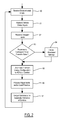
- FIG. 2 is a general flowchart showing one method of the present invention.
- FIG. 3 is a plot showing automatic activation of various thermal devices according to different HVAC modes used in the present invention.
- FIG. 4 is a plot showing the variability of recirculated air in one embodiment.
- an automotive vehicle includes a driver seat 10 , a passenger seat 11 , and a rear seat 12 (which may be a bench seat, rear bucket seats, is or a third row seat).
- a steering wheel 13 located in front of driver seat 10 includes an internal heat source on the surfaces contacted by the driver's hands (i.e., a touchpoint surface).
- a known manner of heating steering wheel 31 may be used such as electrical resistance heating based on a positive temperature coefficient (PTC) material built into the steering wheel.
- PTC positive temperature coefficient
- Additional touchpoint surfaces are preferably included in seats 10 - 12 to conduct heat to or from the occupants.
- seat thermal units 15 - 17 can provide heating and/or cooling using known methods such as integral resistive heating elements, integrated chillers, or thermoelectric devices.
- an auxiliary HVAC 18 could alternatively be used to heat or cool one or more touchpoint surfaces.
- the vehicle includes a forced-air HVAC system having a blower 20 , a cooling heat exchanger 21 such as an evaporator, and a heat exchanger 22 such as a heater core.
- Blower 20 receives air via a blend unit 23 having a door 24 controllably positioned to select relative proportions of either fresh air or inside air. The position of door 24 is known as a recirculation position. It is determined by a controller 25 which also controls a blower motor 26 to determine the blower speed.
- Heat exchangers 21 and 22 may likewise be controlled by controller 25 so that air can be heated or cooled by driving it through heat exchangers 21 and 22 by blower 20 to flow into duct 27 for delivery to various registers.
- the registers include driver registers 30 and 31 .
- the amount of air flow to registers 30 and 31 may be adjusted by a control valve (i.e., damper) 32 under control of controller 25 .
- forced-air can be delivered to a defrost register 33 via a valve 34 .
- Front-seat passenger registers 35 and 36 receive forced air via additional ducts (not shown).
- the ducts include additional dampers (now shown) so that respective zones of forced air 37 and 38 can be selectably controlled by controller 25 . Only some of the registers, inlets, and outlets of a typical climate system are shown in FIG. 1 .
- Forced air zones may also be provided for rear seat passengers including a zone 40 having a register 41 (which may be installed in a floor or ceiling), and a is register 42 which may be installed in a console 43 .
- a second rear seat zone 44 is created using registers 45 and 46 .
- Controller 25 coordinates operation of all the thermal devices by adopting various HVAC modes to efficiently provide comfort for the occupants.
- Controller 25 is coupled to a plurality of sensors 50 which measure a plurality of vehicle status parameters including cabin temperature, cabin humidity, a seat occupancy configuration, outside temperature, outside humidity, cabin pollutant level (such as CO 2 level), sun location, sun intensity, and any other parameters useful for determining occupant comfort.
- a human machine interface (HMI) 51 such as a control panel is connected to controller 25 to allow an occupant to specify a target temperature setting and to generate other commands associated with the HVAC system.
- HMI human machine interface
- an engine 52 In an internal combustion vehicle, an engine 52 generates the energy for operating the thermal units (which may include thermal waste heat or mechanical or electrical energy).
- the thermal units For heating, the thermal units include a supply of heated coolant that circulates from the engine to a heater core.
- the thermal units For cooling, the thermal units include a compressor 53 providing a refrigerant to an evaporator.
- An engine control unit (ECU) 54 controls engine operation and is connected to controller 25 to communicate vehicle status parameters such as a vehicle speed and an engine status.
- a state-of-charge (SOC) circuit 56 provides a battery state-of-charge vehicle status parameter to controller 25 together with other parameters that may be used to define the energy state of battery 55 .
- Controller 25 is configured to operate all the thermal units and associated devices in the HVAC system based on various vehicle status parameters so that the touchpoint heated or cooled surfaces and the forced-air supplied to the occupants achieves optimal comfort and minimal energy consumption.
- controller 25 may preferably operate according to a general method shown in FIG. 2 .
- the method starts in step 60 wherein environmental inputs are received by the controller.
- the environmental inputs may include inside and outside temperature and humidity, solar intensity and position, and others.
- the controller receives vehicle status inputs such as engine coolant temperature, battery state-of-charge, and engine status.
- the controller receives occupant inputs to determine a seat occupancy configuration.
- Seat occupancy sensors may include seat load sensors, seatbelt buckle sensors, manually-operated input switches, and other known means for determining which seats contain an occupant.
- the controller checks to determine whether the vehicle status parameters correspond to an override state.
- the override states correspond to any special cause having some overriding priority that is used to prevent the controller from merely optimizing comfort and economy.
- Overriding priorities may include safety or capability of the vehicle to reach a destination, for example.
- One special cause may be a frosted or fogged windshield or other window pane which must be defrosted or defogged for safe driving.
- Another example may include pollution or contamination in the cabin air such as accumulation of carbon dioxide.
- Another special cause relates to an engine status or battery state-of-charge corresponding with degraded powertrain performance known as a limp-home mode.
- the mandated settings may include forced-air heating being supplied to defrost registers and/or the activation of embedded window-heating elements.
- the mandated settings may include decreasing the recirculation position of the blower input so that increased fresh air is drawn into the passenger cabin. The ratio of fresh air to recirculated air may be increased by a fixed amount or, alternatively, the blend may be set to a predetermined value such as 100% fresh air.
- the mandated settings may include deactivation of at least a portion of the HVAC comfort system, such as turning off of all air conditioning functions.
- step 63 the controller determines a minimum energy configuration to achieve occupant comfort in step 65 .
- those settings would be undisturbed by any configuration commands made in step 65 .
- the automatic selection of an HVAC mode and activation of particular thermal devices are only made if not prevented by any mandated settings.
- the optimum HVAC configuration may be determined by accessing one or more look up tables (LUTs) or by evaluating algorithms correlating various vehicle status parameters to respective commanded values for various control signals used in the HVAC comfort system.
- LUTs look up tables
- FIG. 3 A potential relationship between the vehicle status parameters and the commanded output that can be built into a LUT and/or algorithmic model is shown in FIG. 3 and will be described in more detail below.
- the HVAC configuration including any commanded values determined from the LUTs or models are taken as initial or default values that may be altered by processing adjustments and/or load priorities in step 66 . After the adjustments, commands for automatic activation of various devices are output in step 67 .
- FIG. 3 shows example relationships between adjustable levels of various device settings in response to cabin temperature.
- the cabin temperature may range from ⁇ 40° C. to 80° C. along an axis 70 , for example.
- a predetermined target temperature or a user defined target temperature 71 may be at about 22° C.
- Operation of the HVAC comfort system generally falls into three modes at different cabin temperatures, including an extremity heating mode 72 , a core-plus mode 73 , and a panel circulation mode 74 . At the coldest temperatures in the extremity heating mode 72 , emphasis is on maximum heat delivery via conductive thermal units resulting in sufficient warming of the occupant's extremities.
- all the devices of the comfort system may be operated at relatively low energy in order to thermally condition each occupants' body core plus their extremities.
- the panel circulation mode 74 at the highest temperatures, airflow is the most important element of perceived comfort of the occupant's core plus extremities. Therefore, air circulation via the instrument panel registers is emphasized in panel circulation mode 74 .
- Extremity heating mode 72 is comprised of automatic activation of a touchpoint heated surface in response to the seat occupancy configuration.
- the touchpoint heating surface is activated to a high level as shown by a trace 75 in FIG. 3 .
- a heated steering wheel would also be activated as shown along a trace 76 .
- both the heated seats and heated steering wheel would be activated at 100% power levels as a default value (this would also increase the load on the internal combustion engine to thereby generate more waste heat which can then be used for convective heat).
- the default power levels decrease until the touchpoint heating surfaces are deactivated at a temperature selected for providing comfort according to environmental conditions.
- Other heating devices such as a touchpoint heated shifter or console would be similarly controlled.
- Extremity heating mode 72 may also include convective heating as appropriate.
- Trace 77 illustrates a magnitude of engine coolant flow directed to the heater core in the air handling unit. A maximum flow occurs at the lowest temperatures and decreases to a substantially zero flow at the target comfort temperature.
- a blower speed shown by trace 78 has a default level at a high level (but less than maximum) for the lowest temperatures, and falls off as cabin temperature approaches the target comfort temperature.
- a compressor speed or stroke shown by a trace 80 remains at zero. Across core-plus mode 73 , compressor speed or stroke gradually increases and then reaches a high or maximum level in panel circulation mode 74 .
- the default blower speed may be at a minimum value at the target comfort temperature and throughout most of the core-plus mode 73 . Blower speed increases across panel circulation mode 74 and reaches a maximum at the highest cabin temperatures.
- energy consumption may be reduced by only directing conditioned air to occupied zones. At the highest cabin temperatures, it may be desirable to also supply cooled air to unoccupied zones to better achieve a comfortable temperature in the occupied zones.
- a trace 81 shows activation of cooled seats in the panel circulation mode 74 .
- the touchpoint cooled surfaces of occupied seats may be the last to be activated according to an efficient operation of the HVAC comfort system.
- the curves shown in FIG. 3 are merely examples of desirable levels for the various commands.
- the corresponding levels may be stored in LUT or generated using predetermined algorithms.
- the various adjustments to the default values obtained from FIG. 3 may include certain reprioritization of loads or adjustments that take advantage of opportunities to reduce energy consumption or increase comfort.
- the blower speed could be adjusted in response to vehicle speed. When the vehicle travels over a threshold speed, a ram effect in the outside fresh air intakes may provide sufficient flow to allow a reduction in the blower speed.
- the controller may check for an engine coolant temperature being below a threshold temperature. Before the engine has reached a normal operating temperature, the coolant may contain insufficient heat to heat the cabin quickly. Thus, in response to the engine coolant temperature being below the threshold temperature, default values for operating the touchpoint heated surfaces may be increased while the default blower speed may be reduced.
- FIG. 4 shows another embodiment wherein a commanded recirculation level is determined in response to cabin temperature and/or a temperature-humidity index.
- a 100% recirculation level corresponds to a blend door setting that blocks fresh outside air and a 0% setting corresponds to the blower input receiving only fresh outside air.
- a trace 85 illustrates default levels wherein all internal air is recirculated at 86 when the temperature/humidity index is lowest. With increasing temperature/humidity, recirculation level is gradually decreased at 87 . Around a target comfort range, recirculation may be set to a zero level at 88 when the outside temperature and humidity correspond closely to the desired cabin conditions (which would enable a higher blower setting for increased perception of cooling while consuming less energy to run the blower).
- the recirculation setting is increased at 89 and corresponds to 100% at location 90 in trace 85 .
- the default values obtained from FIG. 4 may be adjusted according to either humidity concerns or pollution concerns.
- the recirculation position may be decreased in proportion to the cabin humidity or in proportion to a cabin pollution level, for example.
- various optimization algorithms may be included wherein inside and outside humidity levels, and inside and outside temperature levels, may indicate that the use of fresh outside air can quickly improve the comfort level inside the passenger cabin regardless of other variables.
- a recirculation position obtaining maximum fresh air may be selected as described above.
Abstract
Description
Claims (5)
Priority Applications (4)
| Application Number | Priority Date | Filing Date | Title |
|---|---|---|---|
| US13/158,940 US9150132B2 (en) | 2011-06-13 | 2011-06-13 | Vehicle comfort system with efficient coordination of complementary thermal units |
| DE102012208593A DE102012208593A1 (en) | 2011-06-13 | 2012-05-23 | VEHICLE COMFORT SYSTEM WITH EFFICIENT COORDINATION OF COMPLEMENTARY THERMAL UNITS |
| CN201210191978.1A CN102826028B (en) | 2011-06-13 | 2012-06-11 | There is the vehicle comfort system efficiently coordinated of auxiliary hot cell |
| US14/837,392 US9758015B2 (en) | 2011-06-13 | 2015-08-27 | Vehicle comfort system with efficient coordination of complementary thermal units |
Applications Claiming Priority (1)
| Application Number | Priority Date | Filing Date | Title |
|---|---|---|---|
| US13/158,940 US9150132B2 (en) | 2011-06-13 | 2011-06-13 | Vehicle comfort system with efficient coordination of complementary thermal units |
Related Child Applications (1)
| Application Number | Title | Priority Date | Filing Date |
|---|---|---|---|
| US14/837,392 Division US9758015B2 (en) | 2011-06-13 | 2015-08-27 | Vehicle comfort system with efficient coordination of complementary thermal units |
Publications (2)
| Publication Number | Publication Date |
|---|---|
| US20120312520A1 US20120312520A1 (en) | 2012-12-13 |
| US9150132B2 true US9150132B2 (en) | 2015-10-06 |
Family
ID=47292151
Family Applications (2)
| Application Number | Title | Priority Date | Filing Date |
|---|---|---|---|
| US13/158,940 Expired - Fee Related US9150132B2 (en) | 2011-06-13 | 2011-06-13 | Vehicle comfort system with efficient coordination of complementary thermal units |
| US14/837,392 Expired - Fee Related US9758015B2 (en) | 2011-06-13 | 2015-08-27 | Vehicle comfort system with efficient coordination of complementary thermal units |
Family Applications After (1)
| Application Number | Title | Priority Date | Filing Date |
|---|---|---|---|
| US14/837,392 Expired - Fee Related US9758015B2 (en) | 2011-06-13 | 2015-08-27 | Vehicle comfort system with efficient coordination of complementary thermal units |
Country Status (3)
| Country | Link |
|---|---|
| US (2) | US9150132B2 (en) |
| CN (1) | CN102826028B (en) |
| DE (1) | DE102012208593A1 (en) |
Cited By (13)
| Publication number | Priority date | Publication date | Assignee | Title |
|---|---|---|---|---|
| US20150360538A1 (en) * | 2011-06-13 | 2015-12-17 | Ford Global Technologies, Llc | Vehicle comfort system with efficient coordination of complementary thermal units |
| US20160068044A1 (en) * | 2013-04-12 | 2016-03-10 | Denso Corporation | Radiant heater air-conditioning system |
| US20160297420A1 (en) * | 2013-12-03 | 2016-10-13 | Renault S.A.S. | Energy management method on a hybrid vehicle comprising a transmission with discrete ratios |
| US20180117992A1 (en) * | 2016-10-27 | 2018-05-03 | Ford Global Technologies, Llc | Method for operating a vehicle air-conditioning system |
| US20180257523A1 (en) * | 2013-09-09 | 2018-09-13 | Faurecia Sieges D'automobile | Motor Vehicle Seat And Method For Managing The Comfort Of Such A Motor Vehicle Seat |
| US10259360B2 (en) * | 2015-09-08 | 2019-04-16 | Ts Tech Co., Ltd. | Seat |
| US10369865B2 (en) | 2014-09-22 | 2019-08-06 | Ford Global Technologies, Llc | Directional climate control system with infrared targeting |
| US10532661B2 (en) | 2017-08-21 | 2020-01-14 | Ford Global Technologies, Llc | System and method for heating electrified vehicle |
| US10556481B2 (en) | 2017-06-26 | 2020-02-11 | Toyota Motor Engineering & Manufacturing North America, Inc. | Systems and methods for providing heating and cooling to a vehicle cabin of autonomous vehicles |
| US10875386B2 (en) | 2016-08-23 | 2020-12-29 | Toyota Motor Engineering & Manufacturing North America, Inc. | Variable compressor control for vehicle air conditioning |
| WO2022197546A1 (en) * | 2021-03-16 | 2022-09-22 | Gentherm Incorporated | Microclimate system for a vehicle occupant and corresponding method |
| US20230025812A1 (en) * | 2021-07-26 | 2023-01-26 | Rivian Ip Holdings, Llc | Cabin climate control based on cabin occupancy |
| US11634005B2 (en) | 2017-12-08 | 2023-04-25 | Ford Global Technologies, Llc | Automatic control of heating and cooling of a vehicle seating assembly pursuant to predictive modeling that recalibrates based on occupant manual control |
Families Citing this family (48)
| Publication number | Priority date | Publication date | Assignee | Title |
|---|---|---|---|---|
| KR101189417B1 (en) * | 2010-11-30 | 2012-10-15 | 기아자동차주식회사 | Temperature Control Apparatus for Vehicle |
| JP5370402B2 (en) * | 2011-03-28 | 2013-12-18 | 株式会社デンソー | Air conditioner for vehicles |
| JP5533812B2 (en) * | 2011-07-28 | 2014-06-25 | 株式会社デンソー | Air conditioner for vehicles |
| US9434235B2 (en) * | 2011-08-29 | 2016-09-06 | Nissan North America, Inc. | Vehicle air handling system |
| DE102012208970A1 (en) * | 2012-05-29 | 2013-12-05 | Manitowoc Crane Group France Sas | Automated cab cabin climate control |
| US9168810B2 (en) * | 2012-10-09 | 2015-10-27 | Delphi Technologies, Inc. | Heating and cooling system for occupants of the rear portion of a vehicle |
| CN105008160B (en) * | 2012-12-28 | 2017-03-15 | 冷王公司 | For controlling the method and system of the operating of condenser fan and evaporator fan |
| US9981578B2 (en) * | 2013-02-22 | 2018-05-29 | Kongsberg Automotive Ab | Vehicle assembly and method of allocating power in the same |
| CN104070959B (en) * | 2013-03-28 | 2017-10-24 | 浙江三花汽车零部件有限公司 | Obtain the method and its control system of environment temperature |
| JP2014240733A (en) * | 2013-06-12 | 2014-12-25 | パナソニックIpマネジメント株式会社 | Environment determination system, environment determination program and apparatus selection device |
| US20150017899A1 (en) * | 2013-07-11 | 2015-01-15 | Kia Motors Corp. | System for mixing cabin air and outside air of air-conditioner for vehicle and method of controlling the same |
| DE102013221516A1 (en) * | 2013-10-23 | 2015-04-23 | Bayerische Motoren Werke Aktiengesellschaft | An air supply device for a vehicle seat and method for operating the air supply device |
| DE102013019305A1 (en) * | 2013-11-16 | 2015-05-21 | Hella Kgaa Hueck & Co. | Method and device for determining at least one control signal for controlling an air conditioning device |
| US20150197135A1 (en) * | 2014-01-13 | 2015-07-16 | GM Global Technology Operations LLC | Systems for improving vehicle occupant climate comfort via steering assembly air delivery |
| CN104251547B (en) * | 2014-09-23 | 2017-03-22 | 中国商用飞机有限责任公司 | Dewatering device for air conditioning system of airplane |
| DE102014219408A1 (en) * | 2014-09-25 | 2016-04-14 | Volkswagen Aktiengesellschaft | Method and device for setting a thermal comfort state |
| DE102014222139A1 (en) * | 2014-10-30 | 2016-05-04 | Bayerische Motoren Werke Aktiengesellschaft | motor vehicle |
| CN107000537B (en) * | 2014-10-31 | 2021-03-12 | 金瑟姆股份有限公司 | Vehicle microclimate system and control method thereof |
| KR101610539B1 (en) * | 2014-11-13 | 2016-04-07 | 현대자동차주식회사 | Apparatus and method for restraining microbial propagation on a surface of an evaporator for vehicle |
| US9849751B2 (en) | 2015-01-14 | 2017-12-26 | Ford Global Technologies, Llc | Adaptive control of automotive HVAC system using crowd-sourcing data |
| US10279650B2 (en) * | 2015-01-27 | 2019-05-07 | Ford Global Technologies, Llc | Adaptive vehicle climate control system and method |
| DE102015205136A1 (en) * | 2015-03-20 | 2016-09-22 | Volkswagen Aktiengesellschaft | Method for deicing a heat exchanger of an air conditioning device of a motor vehicle |
| FR3040658B1 (en) | 2015-09-08 | 2018-12-07 | Valeo Systemes Thermiques | THERMAL MANAGEMENT SYSTEM FOR MOTOR VEHICLE AND THERMAL MANAGEMENT METHOD THEREOF |
| WO2017062025A1 (en) | 2015-10-09 | 2017-04-13 | Volvo Truck Corporation | Managing the energy consumption of a multiple zone heating, ventilating and air conditioning system for a vehicle and method |
| KR20170071013A (en) * | 2015-12-15 | 2017-06-23 | 현대자동차주식회사 | Apparatus and method for air cleaning of vehicle |
| CN106956626A (en) * | 2016-01-11 | 2017-07-18 | 卡孚特能源技术(深圳)有限公司 | A kind of semiconductor seat-air conditioning system |
| JP6358567B2 (en) * | 2016-01-26 | 2018-07-18 | マツダ株式会社 | Seat heater control device using electrostatic sensor |
| CN107234936A (en) * | 2016-03-28 | 2017-10-10 | 福特环球技术公司 | Air pollution reaction system in vehicle |
| CN106042825A (en) * | 2016-05-27 | 2016-10-26 | 乐视控股(北京)有限公司 | Riding comfort regulation system and regulation method |
| DE102016112667A1 (en) * | 2016-07-11 | 2018-01-11 | Bombardier Transportation Gmbh | A method of operating a system for air conditioning an interior of a vehicle |
| DE102016219653A1 (en) * | 2016-10-11 | 2018-04-26 | Continental Automotive Gmbh | Heating arrangement for a vehicle component |
| US10591878B2 (en) * | 2016-12-09 | 2020-03-17 | Ademco Inc. | Providing integrative comfort in a structure |
| US10457200B2 (en) | 2017-06-27 | 2019-10-29 | Michael T. Gage | Abandoned occupant danger alert system |
| US10479163B2 (en) * | 2017-11-14 | 2019-11-19 | GM Global Technology Operations LLC | Method for controlling a thermal comfort control system for ride share vehicles |
| US10640137B2 (en) | 2018-02-20 | 2020-05-05 | Ford Global Technologies, Llc | Automatic control of a heating element in a steering wheel of a vehicle pursuant to predictive modeling that recalibrates based on occupant manual control of the heating element |
| US20190366793A1 (en) * | 2018-05-29 | 2019-12-05 | GM Global Technology Operations LLC | Method and apparatus for control of vehicle ventilation in response to carbon dioxide estimation |
| CN109050198A (en) * | 2018-07-27 | 2018-12-21 | 上海思致汽车工程技术有限公司 | Heat management domain control system in a kind of pure electric automobile cabin |
| CA3132040A1 (en) * | 2019-03-01 | 2020-09-10 | Henry I. Patel | Ptac unit with dynamic intelligent air management system |
| US11433742B2 (en) | 2019-06-11 | 2022-09-06 | Ford Global Technologies, Llc | Automatic control of a heating element in thermal communication with a rear window of a vehicle pursuant to predictive modeling that recalibrates based on occupant manual control of the heating element |
| US11427199B2 (en) | 2019-08-22 | 2022-08-30 | Ford Global Technologies Llc | System for aligning a vehicle hitch location identifier with a trailer coupler |
| DE102019124054A1 (en) * | 2019-09-09 | 2021-03-11 | Hanon Systems | Vehicle air conditioning arrangement and method for operating a vehicle air conditioning arrangement |
| KR20210030553A (en) * | 2019-09-09 | 2021-03-18 | 현대자동차주식회사 | Hvac system of vehicle |
| CN110641250B (en) * | 2019-11-05 | 2022-07-15 | 重庆大学 | Intelligent control method of air conditioning system of electric automobile based on human body thermal comfort theory and fuzzy PID control |
| CN111731070B (en) * | 2020-08-01 | 2020-11-20 | 深圳小木科技有限公司 | Vehicle-mounted air conditioner and carriage air conditioning method |
| FR3125748A1 (en) * | 2021-07-30 | 2023-02-03 | Psa Automobiles Sa | Method for managing an air conditioning installation of a motor vehicle and motor vehicle |
| NL2028983B1 (en) * | 2021-08-17 | 2023-02-23 | Skytree B V | HVAC Recirculation System with Improved Energy Efficiency |
| DE102021125409A1 (en) | 2021-09-30 | 2023-03-30 | Ford Global Technologies, Llc | Controlling the temperature inside a vehicle |
| FR3134349A1 (en) * | 2022-04-06 | 2023-10-13 | Psa Automobiles Sa | process for thermal regulation of a motor vehicle passenger compartment |
Citations (16)
| Publication number | Priority date | Publication date | Assignee | Title |
|---|---|---|---|---|
| US4538760A (en) * | 1982-08-27 | 1985-09-03 | Nissan Shatai Company, Limited | Air conditioner control arrangement for automotive vehicle or the like |
| US5054686A (en) * | 1990-11-05 | 1991-10-08 | Prospect Corporation | Automobile environment management system |
| US5553661A (en) | 1995-10-23 | 1996-09-10 | Delco Electronics Corporation | Solar position correction for climate control system |
| US5878809A (en) * | 1995-07-20 | 1999-03-09 | Mercedes-Benz Ag | Process and system for controlling an air-conditioning system for a vehicle interior |
| US6216956B1 (en) | 1997-10-29 | 2001-04-17 | Tocom, Inc. | Environmental condition control and energy management system and method |
| US6237675B1 (en) * | 1999-06-14 | 2001-05-29 | Ford Global Technolgies, Inc. | Automatic temperature controlled seats |
| US6454178B1 (en) | 2001-05-24 | 2002-09-24 | Ford Global Technologies, Inc. | Adaptive controller for an automotive HVAC system |
| US20030039298A1 (en) * | 2001-08-22 | 2003-02-27 | Lear Corporation | System and method of vehicle climate control |
| US6672085B1 (en) * | 2002-10-24 | 2004-01-06 | Delphi Technologies, Inc. | Hierarchical control method for a motor vehicle HVAC system |
| US6886352B2 (en) * | 2002-09-18 | 2005-05-03 | Denso Corporation | Vehicle air conditioner |
| US6965813B2 (en) | 2000-09-04 | 2005-11-15 | Forskarpatent I Uppsala Ab | Climate control system and method for controlling such |
| US20070114292A1 (en) | 1994-05-09 | 2007-05-24 | Automotive Technologies International, Inc. | Vehicular HVAC Control Systems and Methods |
| US20090000778A1 (en) * | 2007-06-26 | 2009-01-01 | Lear Corporation | Control scheme for an occupant environment conditioning system of a vehicle |
| US20090078781A1 (en) * | 2007-09-20 | 2009-03-26 | Honda Motor Co., Ltd. | Automatic hvac fan operation during warm-up stage |
| US20090301116A1 (en) | 2008-06-09 | 2009-12-10 | Lear Corporation | Climate controlling system |
| US7743651B2 (en) * | 1996-12-17 | 2010-06-29 | Denso Corporation | Method for detecting malfunction of a cooling system based on detected coolant temperature |
Family Cites Families (7)
| Publication number | Priority date | Publication date | Assignee | Title |
|---|---|---|---|---|
| US6675085B2 (en) * | 2000-08-17 | 2004-01-06 | Michael P. Straub | Method and apparatus for storing, accessing, generating and using information about speed limits and speed traps |
| US6857697B2 (en) * | 2002-08-29 | 2005-02-22 | W.E.T. Automotive Systems Ag | Automotive vehicle seating comfort system |
| US7425034B2 (en) * | 2003-10-17 | 2008-09-16 | W.E.T. Automotive Systems Ag | Automotive vehicle seat having a comfort system |
| US7478869B2 (en) * | 2005-08-19 | 2009-01-20 | W.E.T. Automotive Systems, Ag | Automotive vehicle seat insert |
| US7950735B2 (en) * | 2008-04-07 | 2011-05-31 | GM Global Technology Operations LLC | Temperature controlled vehicle seats |
| US20090286459A1 (en) * | 2008-05-15 | 2009-11-19 | Gm Global Technology Operations, Inc. | System and Method to Reduce Thermal Energy in Vehicle Interiors Subjected to Solar Radiation |
| US9150132B2 (en) * | 2011-06-13 | 2015-10-06 | Ford Global Technologies, Llc | Vehicle comfort system with efficient coordination of complementary thermal units |
-
2011
- 2011-06-13 US US13/158,940 patent/US9150132B2/en not_active Expired - Fee Related
-
2012
- 2012-05-23 DE DE102012208593A patent/DE102012208593A1/en not_active Withdrawn
- 2012-06-11 CN CN201210191978.1A patent/CN102826028B/en not_active Expired - Fee Related
-
2015
- 2015-08-27 US US14/837,392 patent/US9758015B2/en not_active Expired - Fee Related
Patent Citations (16)
| Publication number | Priority date | Publication date | Assignee | Title |
|---|---|---|---|---|
| US4538760A (en) * | 1982-08-27 | 1985-09-03 | Nissan Shatai Company, Limited | Air conditioner control arrangement for automotive vehicle or the like |
| US5054686A (en) * | 1990-11-05 | 1991-10-08 | Prospect Corporation | Automobile environment management system |
| US20070114292A1 (en) | 1994-05-09 | 2007-05-24 | Automotive Technologies International, Inc. | Vehicular HVAC Control Systems and Methods |
| US5878809A (en) * | 1995-07-20 | 1999-03-09 | Mercedes-Benz Ag | Process and system for controlling an air-conditioning system for a vehicle interior |
| US5553661A (en) | 1995-10-23 | 1996-09-10 | Delco Electronics Corporation | Solar position correction for climate control system |
| US7743651B2 (en) * | 1996-12-17 | 2010-06-29 | Denso Corporation | Method for detecting malfunction of a cooling system based on detected coolant temperature |
| US6216956B1 (en) | 1997-10-29 | 2001-04-17 | Tocom, Inc. | Environmental condition control and energy management system and method |
| US6237675B1 (en) * | 1999-06-14 | 2001-05-29 | Ford Global Technolgies, Inc. | Automatic temperature controlled seats |
| US6965813B2 (en) | 2000-09-04 | 2005-11-15 | Forskarpatent I Uppsala Ab | Climate control system and method for controlling such |
| US6454178B1 (en) | 2001-05-24 | 2002-09-24 | Ford Global Technologies, Inc. | Adaptive controller for an automotive HVAC system |
| US20030039298A1 (en) * | 2001-08-22 | 2003-02-27 | Lear Corporation | System and method of vehicle climate control |
| US6886352B2 (en) * | 2002-09-18 | 2005-05-03 | Denso Corporation | Vehicle air conditioner |
| US6672085B1 (en) * | 2002-10-24 | 2004-01-06 | Delphi Technologies, Inc. | Hierarchical control method for a motor vehicle HVAC system |
| US20090000778A1 (en) * | 2007-06-26 | 2009-01-01 | Lear Corporation | Control scheme for an occupant environment conditioning system of a vehicle |
| US20090078781A1 (en) * | 2007-09-20 | 2009-03-26 | Honda Motor Co., Ltd. | Automatic hvac fan operation during warm-up stage |
| US20090301116A1 (en) | 2008-06-09 | 2009-12-10 | Lear Corporation | Climate controlling system |
Non-Patent Citations (1)
| Title |
|---|
| Yadolla Farzaneh, et al., Intelligent Control of Thermal Comfort in Automobile, Department of Mechanical Engineering Ferdowsi University of Mashhad, Iran, 2008, 5 pgs. |
Cited By (20)
| Publication number | Priority date | Publication date | Assignee | Title |
|---|---|---|---|---|
| US9758015B2 (en) * | 2011-06-13 | 2017-09-12 | Ford Global Technologies, Llc | Vehicle comfort system with efficient coordination of complementary thermal units |
| US20150360538A1 (en) * | 2011-06-13 | 2015-12-17 | Ford Global Technologies, Llc | Vehicle comfort system with efficient coordination of complementary thermal units |
| US20160068044A1 (en) * | 2013-04-12 | 2016-03-10 | Denso Corporation | Radiant heater air-conditioning system |
| US9873309B2 (en) * | 2013-04-12 | 2018-01-23 | Denso Corporation | Radiant heater air-conditioning system |
| US20180257523A1 (en) * | 2013-09-09 | 2018-09-13 | Faurecia Sieges D'automobile | Motor Vehicle Seat And Method For Managing The Comfort Of Such A Motor Vehicle Seat |
| US20160297420A1 (en) * | 2013-12-03 | 2016-10-13 | Renault S.A.S. | Energy management method on a hybrid vehicle comprising a transmission with discrete ratios |
| US9902391B2 (en) * | 2013-12-03 | 2018-02-27 | Renault S.A.S. | Energy management method on a hybrid vehicle comprising a transmission with discrete ratios |
| US10369865B2 (en) | 2014-09-22 | 2019-08-06 | Ford Global Technologies, Llc | Directional climate control system with infrared targeting |
| US10259360B2 (en) * | 2015-09-08 | 2019-04-16 | Ts Tech Co., Ltd. | Seat |
| US11383624B2 (en) | 2015-09-08 | 2022-07-12 | Ts Tech Co., Ltd. | Seat |
| US10850653B2 (en) | 2015-09-08 | 2020-12-01 | Ts Tech Co., Ltd. | Seat |
| US10875386B2 (en) | 2016-08-23 | 2020-12-29 | Toyota Motor Engineering & Manufacturing North America, Inc. | Variable compressor control for vehicle air conditioning |
| US10981434B2 (en) * | 2016-10-27 | 2021-04-20 | Ford Global Technologies, Llc | Vehicle air-conditioning system and method of operation |
| US20180117992A1 (en) * | 2016-10-27 | 2018-05-03 | Ford Global Technologies, Llc | Method for operating a vehicle air-conditioning system |
| US11247529B2 (en) | 2017-06-26 | 2022-02-15 | Toyota Motor Engineering & Manufacturing North America, Inc. | Systems and methods for providing heating and cooling to a vehicle cabin of autonomous vehicles |
| US10556481B2 (en) | 2017-06-26 | 2020-02-11 | Toyota Motor Engineering & Manufacturing North America, Inc. | Systems and methods for providing heating and cooling to a vehicle cabin of autonomous vehicles |
| US10532661B2 (en) | 2017-08-21 | 2020-01-14 | Ford Global Technologies, Llc | System and method for heating electrified vehicle |
| US11634005B2 (en) | 2017-12-08 | 2023-04-25 | Ford Global Technologies, Llc | Automatic control of heating and cooling of a vehicle seating assembly pursuant to predictive modeling that recalibrates based on occupant manual control |
| WO2022197546A1 (en) * | 2021-03-16 | 2022-09-22 | Gentherm Incorporated | Microclimate system for a vehicle occupant and corresponding method |
| US20230025812A1 (en) * | 2021-07-26 | 2023-01-26 | Rivian Ip Holdings, Llc | Cabin climate control based on cabin occupancy |
Also Published As
| Publication number | Publication date |
|---|---|
| US20120312520A1 (en) | 2012-12-13 |
| US20150360538A1 (en) | 2015-12-17 |
| US9758015B2 (en) | 2017-09-12 |
| CN102826028A (en) | 2012-12-19 |
| CN102826028B (en) | 2016-07-20 |
| DE102012208593A1 (en) | 2013-01-03 |
Similar Documents
| Publication | Publication Date | Title |
|---|---|---|
| US9758015B2 (en) | Vehicle comfort system with efficient coordination of complementary thermal units | |
| US10279650B2 (en) | Adaptive vehicle climate control system and method | |
| US9902303B2 (en) | Vehicle air-conditioning system provided with seat air-conditioning unit | |
| CN201506355U (en) | System for controlling vehicle climate control system by remote starting | |
| US8859938B2 (en) | Vehicle cabin heating system | |
| US8082979B2 (en) | System and method for environmental management of a vehicle | |
| CN103448506B (en) | The control method of vehicle air regulation | |
| US20090000778A1 (en) | Control scheme for an occupant environment conditioning system of a vehicle | |
| US20140083672A1 (en) | Automatic Recirculation Control for Vehicular HVAC System | |
| US20060118290A1 (en) | HVAC system for a work vehicle | |
| US20160167478A1 (en) | Air conditioning system for motor vehicles | |
| US20120252341A1 (en) | Hvac control for multi-blower unit | |
| US11267317B2 (en) | System for controlling inside/outside air in air conditioner | |
| EP3359401B1 (en) | Managing the energy consumption of a multiple zone heating, ventilating and air conditioning system for a vehicle and method | |
| US20140053590A1 (en) | Vehicle air handling system | |
| JP6019776B2 (en) | Air conditioner for vehicles | |
| US20160332502A1 (en) | Hvac control for vehicles with start/stop engines | |
| CN112424005B (en) | Fully variable and integral ventilation valve control device | |
| JP2006298037A (en) | Vehicle seat air conditioner | |
| US11091005B2 (en) | Ventilation bed for vehicle and method for controlling the same | |
| KR102437435B1 (en) | Air conditioning system for automotive vehicles | |
| JP2007216792A (en) | Vehicular air-conditioner | |
| US20240116328A1 (en) | Method of controlling air-conditioning for occupants through seating detection |
Legal Events
| Date | Code | Title | Description |
|---|---|---|---|
| AS | Assignment |
Owner name: FORD GLOBAL TECHNOLOGIES, LLC, MICHIGAN Free format text: ASSIGNMENT OF ASSIGNORS INTEREST;ASSIGNORS:HOKE, PAUL B.;LINE, JOHNATHAN A.;DAGE, GARY A.;AND OTHERS;REEL/FRAME:026433/0855 Effective date: 20110610 |
|
| STCF | Information on status: patent grant |
Free format text: PATENTED CASE |
|
| MAFP | Maintenance fee payment |
Free format text: PAYMENT OF MAINTENANCE FEE, 4TH YEAR, LARGE ENTITY (ORIGINAL EVENT CODE: M1551); ENTITY STATUS OF PATENT OWNER: LARGE ENTITY Year of fee payment: 4 |
|
| FEPP | Fee payment procedure |
Free format text: MAINTENANCE FEE REMINDER MAILED (ORIGINAL EVENT CODE: REM.); ENTITY STATUS OF PATENT OWNER: LARGE ENTITY |
|
| LAPS | Lapse for failure to pay maintenance fees |
Free format text: PATENT EXPIRED FOR FAILURE TO PAY MAINTENANCE FEES (ORIGINAL EVENT CODE: EXP.); ENTITY STATUS OF PATENT OWNER: LARGE ENTITY |
|
| STCH | Information on status: patent discontinuation |
Free format text: PATENT EXPIRED DUE TO NONPAYMENT OF MAINTENANCE FEES UNDER 37 CFR 1.362 |
|
| FP | Lapsed due to failure to pay maintenance fee |
Effective date: 20231006 |