US9150067B2 - Underbed support assembly for fifth wheel and gooseneck hitch systems - Google Patents
Underbed support assembly for fifth wheel and gooseneck hitch systems Download PDFInfo
- Publication number
- US9150067B2 US9150067B2 US14/050,836 US201314050836A US9150067B2 US 9150067 B2 US9150067 B2 US 9150067B2 US 201314050836 A US201314050836 A US 201314050836A US 9150067 B2 US9150067 B2 US 9150067B2
- Authority
- US
- United States
- Prior art keywords
- mounting
- mounting pads
- single cross
- suspension
- pads
- Prior art date
- Legal status (The legal status is an assumption and is not a legal conclusion. Google has not performed a legal analysis and makes no representation as to the accuracy of the status listed.)
- Active, expires
Links
Images


Classifications
-
- B—PERFORMING OPERATIONS; TRANSPORTING
- B60—VEHICLES IN GENERAL
- B60D—VEHICLE CONNECTIONS
- B60D1/00—Traction couplings; Hitches; Draw-gear; Towing devices
- B60D1/48—Traction couplings; Hitches; Draw-gear; Towing devices characterised by the mounting
-
- B—PERFORMING OPERATIONS; TRANSPORTING
- B60—VEHICLES IN GENERAL
- B60D—VEHICLE CONNECTIONS
- B60D1/00—Traction couplings; Hitches; Draw-gear; Towing devices
- B60D1/01—Traction couplings or hitches characterised by their type
- B60D1/015—Fifth wheel couplings
-
- B—PERFORMING OPERATIONS; TRANSPORTING
- B60—VEHICLES IN GENERAL
- B60D—VEHICLE CONNECTIONS
- B60D1/00—Traction couplings; Hitches; Draw-gear; Towing devices
- B60D1/01—Traction couplings or hitches characterised by their type
- B60D1/06—Ball-and-socket hitches, e.g. constructional details, auxiliary devices, their arrangement on the vehicle
- B60D1/065—Ball-and-socket hitches, e.g. constructional details, auxiliary devices, their arrangement on the vehicle characterised by the hitch mechanism
-
- B—PERFORMING OPERATIONS; TRANSPORTING
- B60—VEHICLES IN GENERAL
- B60D—VEHICLE CONNECTIONS
- B60D1/00—Traction couplings; Hitches; Draw-gear; Towing devices
- B60D1/48—Traction couplings; Hitches; Draw-gear; Towing devices characterised by the mounting
- B60D1/488—Traction couplings; Hitches; Draw-gear; Towing devices characterised by the mounting mounted directly to the chassis of the towing vehicle
-
- B—PERFORMING OPERATIONS; TRANSPORTING
- B62—LAND VEHICLES FOR TRAVELLING OTHERWISE THAN ON RAILS
- B62D—MOTOR VEHICLES; TRAILERS
- B62D21/00—Understructures, i.e. chassis frame on which a vehicle body may be mounted
- B62D21/11—Understructures, i.e. chassis frame on which a vehicle body may be mounted with resilient means for suspension, e.g. of wheels or engine; sub-frames for mounting engine or suspensions
-
- B—PERFORMING OPERATIONS; TRANSPORTING
- B62—LAND VEHICLES FOR TRAVELLING OTHERWISE THAN ON RAILS
- B62D—MOTOR VEHICLES; TRAILERS
- B62D53/00—Tractor-trailer combinations; Road trains
- B62D53/04—Tractor-trailer combinations; Road trains comprising a vehicle carrying an essential part of the other vehicle's load by having supporting means for the front or rear part of the other vehicle
- B62D53/08—Fifth wheel traction couplings
Definitions
- the present disclosure relates generally to a towing apparatus for a vehicle and, more particularly, to an underbed hitch mounting assembly for the vehicle.
- an apparatus for attaching either a gooseneck trailer hitch or a fifth wheel trailer hitch to a truck bed can include a single cross-member, a gooseneck ball receiver and a plurality of mounting pads.
- the single cross-member can be attached to first and second truck longitudinal frame rails.
- the gooseneck ball receiver can be coupled to the single cross-member and aligned with a gooseneck hitch opening in the truck bed.
- the plurality of mounting pads can be spaced apart from the single cross-member and can be attached to the frame rails independent of the single cross-member.
- the plurality of mounting pads can be aligned with a corresponding plurality of access openings in the truck bed.
- the single cross-member can be a suspension cross-member supporting at least first and second suspension members.
- an apparatus for attaching either a gooseneck trailer hitch or a fifth wheel trailer hitch to a truck bed can include a single cross-member, a gooseneck ball receiver and first and second pairs of mounting pads.
- the single cross-member can be attached to first and second truck longitudinal frame rails, and can support first and second suspension components.
- the gooseneck ball receiver can be coupled to the single cross-member and can be aligned with a gooseneck hitch opening in the truck bed.
- the first and second pairs of mounting pads can be spaced apart from the single cross-member and can be attached to the respective first and second frame rails independent of the single cross-member and each other.
- the first and second pairs of mounting pads can be aligned with corresponding first and second pairs of access openings in the truck bed.
- a first mounting bracket can be associated with one of the first pair of mounting pads and a second mounting bracket can be associated with one of the second pair of mounting pads and can support respective third and fourth shock members.
- FIG. 1 is a perspective view of components of an exemplary underbed support structure assembly for accommodating either a fifth wheel trailer hitch or a gooseneck trailer hitch according to the principles of the present disclosure
- FIG. 2 is a perspective view of the underbed support structure assembly associated with a pickup truck vehicle according to the principles of the present disclosure
- FIG. 3 is a bottom view of the components of the exemplary underbed support structure assembly of FIG. 1 shown in connection with an underside of a cargo bed load floor according to the principles of the present disclosure
- FIG. 4 is a perspective view of the exemplary underbed support structure assembly mounted to the vehicle along with associated suspension components according to the principles of the present disclosure
- FIG. 5 is an exploded view of a mounting pad and bracket assembly of the underbed support structure assembly according to the principles of the present disclosure
- FIG. 6 is a perspective view of a cargo bed load floor of a pickup truck showing the underbed support structure assembly in relation thereto when the gooseneck trailer hitch and the fifth wheel trailer hitch are dismounted according to the principles of the present disclosure;
- FIG. 7 is a perspective view of the cargo bed load floor of the pickup truck showing the underbed support structure assembly in relation thereto when a gooseneck trailer hitch and safety chain tie downs are mounted according to the principles of the present disclosure
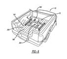
- FIG. 8 is a perspective view of the cargo bed load floor of the pickup truck showing the underbed support structure assembly in relation thereto when a fifth wheel trailer hitch is mounted according to the principles of the present disclosure.
- an exemplary underbed support structure assembly is shown and generally identified at reference numeral 10 .
- the underbed support structure assembly 10 can selectively accommodate either a fifth wheel hitch or a gooseneck hitch.
- the underbed support structure assembly 10 can be positioned under a load floor of a cargo bed such that the support structure assembly 10 does not protrude into or interfere with use of the cargo bed load floor.
- the support structure assembly 10 can, in an exemplary implementation, take advantage of existing vehicle structural members so as to reduce a need for packaging one or more additional support structure frame members to support the gooseneck hitch. Reducing a need for such additional frame members can also reduce manufacturing cost and complexity associated with, for example, manufacturing different models of a pickup truck that will and will not receive the support structure assembly 10 .
- the underbed support structure assembly 10 can position mounting pads over longitudinal frame rails of the vehicle without requiring additional cross-member structural supports.
- One or more of the mounting pads can be configured to selectively couple a fifth wheel hitch or safety chain attachments for a gooseneck hitch.
- the mounting pads can be spaced apart from and separate from a suspension cross-member that is configured to also support a gooseneck ball receiver, as will also be discussed in greater detail below.
- the underbed support structure assembly 10 can include, in the exemplary implementation illustrated, a structural gooseneck hitch receiving member 14 and four mounting pads 26 .
- the structural gooseneck hitch receiving member 14 can define a receiving feature 22 for a gooseneck hitch/ball 18 ( FIG. 7 ).
- the structural gooseneck hitch receiving member 14 can be coupled to an existing vehicle frame member, such as an air suspension cross-member 34 .
- the air suspension cross-member 34 can extend between the longitudinal frame rails 38 of pickup truck or vehicle 42 .
- the air suspension cross-member 34 can support air suspension components 40 , as well as other suspension components including non-air suspension and vehicle components.
- the structural gooseneck hitch receiving member 14 can be a structural casting 14 formed from steel or a steel alloy. Various other metals and metal alloys can also be used to form the structural casting 14 , as may be desired depending on vehicle and application design considerations. While the structural gooseneck hitch receiving member will be referred to hereinafter as a structural casting 14 , it should be appreciated that the structural hitch receiving member can be formed from various manufacturing methods, such as a stamping operation.
- the structural casting 14 in the exemplary implementation illustrated, can include a larger width 44 than length 48 and can include a plurality of ribs 52 that extend from the gooseneck ball receiving feature 22 to lateral ends 56 or longitudinal ends 60 .
- the lateral ends 56 can include a thicker or reinforced area 64 configured to receive fasteners to secure the structural casting 14 to the suspension cross-member 34 .
- an upper surface 68 of the suspension cross-member 34 can include locating projections 72 configured to aid in assembling the structural casting 14 to the suspension cross-member 34 .
- the structural casting 14 can be mounted to a lower surface of the suspension cross-member 34 such that the upper surface 68 of the structural casting 14 faces and/or engages the lower surface.
- the suspension cross-member 34 is positioned over and covers or substantially covers the structural casting 14 when assembled in vehicle 42 .
- the suspension cross-member 34 can include an aperture 82 configured to provide access through the cross-member 34 to the gooseneck ball receiving feature 22 .
- the structural casting 14 can include a lateral width 44 less than a width of the suspension cross-member 34 and a width between the longitudinal frame rails 38 . It should be appreciated that the length 48 and width 44 of the structural casting 14 can vary depending on, for example, design and packaging criteria for particular vehicles and/or applications.
- the gooseneck ball receiving feature 22 defined by structural casting 14 can be in the form of a socket or receptacle 88 .
- the receptacle 88 can include a cylindrical or substantially cylindrical shape configured to mate with and be complimentary to a corresponding shape of a mating portion of gooseneck ball 18 . It should be appreciated, however, that the receptacle 88 can include various different shapes as may be desired for different vehicle or design applications.
- the receptacle 88 can include a quick-connect receptacle 88 configured to removably receive a quick-connect gooseneck hitch/ball 18 through an access opening in the load floor and the aperture 82 in the suspension cross-member 34 .
- the mounting pads 26 can include a body 92 having an upper surface 96 , an opposed lower surface 100 , inner and outer sides 104 , 108 , a first end 112 and a second opposite end 116 . It should be appreciated, however, that the mounting pads 26 can be formed from various different materials and/or manufacturing methods. It should also be appreciated that the mounting pads may also be referred to as pucks or a puck mounting system.
- the four mounting pads 26 can be mounted directly over the longitudinal frame rails 38 such that they are in-line or substantially in-line with frame rails 38 .
- the mounting pads 26 can be directly above the frame rails 38 such that the lower surface 100 of mounting pads 26 directly faces an upper surface 124 of frame rails 38 .
- the mounting pads 26 can be mounted to the frame rails 38 with pairs of brackets 132 .
- the pairs of brackets 132 can be provided in various forms, including a single bracket mounted to one side of the frame rails and/or a single bracket having two flanges for mounting to opposed sides of the frame rails 38 .
- the pairs of brackets 132 can be coupled to opposed sides of the frame rails 38 and the inner and outer sides 104 , 108 of mounting pads 26 .
- the mounting pad body 92 can define first and second through bores 140 proximate the first and second ends 112 , 116 for receiving fasteners 144 to couple or secure mounting pads 26 to their respective brackets 132 .
- Using fasteners provides an ability to individually service, remove and/or replace each of the mounting pads 26 .
- the body 92 can also define or include an overhang or shoulder 152 on each side 104 , 108 configured to engage an upper end 156 of the brackets 132 . This arrangement can provide additional support for the mounting pads 26 beyond that provided by fasteners 144 when, for example, a fifth wheel hitch is removably mounted thereto.
- the mounting pads 26 can alternatively be coupled to the frame rails 38 using other securing arrangements, such as welding the mounting pads 26 to the brackets 132 and/or frame rails 38 .
- brackets 132 A two of the four pairs of brackets 132 can be used for mounting suspension system components, such as rear shocks 162 .
- two of the four pairs of brackets 132 A are utilized by the vehicle 42 independent of the support structure assembly 10 .
- the support structure assembly 10 advantageously leverages these two existing pairs of brackets 132 A for the additional purpose of mounting two of the mounting pads 26 .
- the two pairs of mounting brackets 132 A that serve as shock mounts can receive a fastener 166 for coupling the rear shocks 162 to the vehicle 42 .
- the lower surface of at least two of the four mounting pads 26 can include a cut-out or clearance area 170 configured to receive a portion of the fastener 166 therein when the mounting pads 26 are fastened to the respective pairs of brackets 132 A, as can be seen in FIG. 5 with reference to FIG. 2 .
- the two pairs of brackets 132 A can be diagonally opposed about opposite sides of the suspension cross-member 34 .
- each of the mounting pads 26 can also define raised load surfaces 174 and a socket or receptacle 178 therethrough.
- the receptacle 178 can be configured to selectively receive either a fifth wheel attachment member, such as a locking pin, for securing a fifth wheel adaptor and/or hitch 180 , or a tie down member 184 for securing gooseneck hitch safety chains (not specifically shown) to vehicle 42 .
- the receptacle 178 can be a quick-connect receptacle configured to removably receive a quick-connect locking pin or a quick-connect tie down member 184 .
- the underbed support structure assembly 10 can accommodate either a fifth wheel hitch 180 or a gooseneck hitch/ball 18 without requiring any modification or conversion.
- the load floor 188 of the pickup truck bed 192 can include an aperture 196 aligned with the gooseneck ball receiving receptacle 88 in structural casting 14 , and four apertures 200 aligned with the load surfaces 174 and receptacles 178 of the respective mounting pads 26 .
- the underbed support structure assembly 10 can be provided on a vehicle with only the fifth wheel mounting pads 26 and associated structure (e.g., mounting brackets 132 ) or only the gooseneck ball/hitch receiver structural casting 14 .
- the gooseneck hitch receiving components and the fifth wheel hitch receiving components can be individually provided on the pickup truck 42 , or provided as a combined package.
- Removable caps or covers 204 can be positioned in apertures 196 , 200 to cover the openings when not in use. One or more of the covers 204 can be selectively removed to provide access to the desired receptacles for mounting either the gooseneck hitch/ball 18 and tie down members 184 , or the fifth wheel hitch 180 .
- the load floor 188 of bed 192 can include a plurality of raised ribs 208 and a height of the covers can be less than or equal to or substantially equal to a height of the raised ribs 208 so as to not interfere with an item being placed on or along load floor 188 .
- the underbed support structure assembly 10 can selectively accommodate either a fifth wheel hitch 180 or a gooseneck hitch/ball 18 while not interfering with use of cargo bed 192 when the gooseneck hitch 18 and fifth wheel hitch 180 are dismounted.
- the underbed support structure assembly 10 can, in an exemplary implementation, take advantage of existing vehicle structural members (e.g., suspension cross-member and suspension mounting brackets) so as to reduce a need for packaging one or more additional frame members thereby reducing manufacturing cost and complexity.
Abstract
Description
Claims (18)
Priority Applications (1)
| Application Number | Priority Date | Filing Date | Title |
|---|---|---|---|
| US14/050,836 US9150067B2 (en) | 2013-10-10 | 2013-10-10 | Underbed support assembly for fifth wheel and gooseneck hitch systems |
Applications Claiming Priority (1)
| Application Number | Priority Date | Filing Date | Title |
|---|---|---|---|
| US14/050,836 US9150067B2 (en) | 2013-10-10 | 2013-10-10 | Underbed support assembly for fifth wheel and gooseneck hitch systems |
Publications (2)
| Publication Number | Publication Date |
|---|---|
| US20150102584A1 US20150102584A1 (en) | 2015-04-16 |
| US9150067B2 true US9150067B2 (en) | 2015-10-06 |
Family
ID=52809060
Family Applications (1)
| Application Number | Title | Priority Date | Filing Date |
|---|---|---|---|
| US14/050,836 Active 2034-01-15 US9150067B2 (en) | 2013-10-10 | 2013-10-10 | Underbed support assembly for fifth wheel and gooseneck hitch systems |
Country Status (1)
| Country | Link |
|---|---|
| US (1) | US9150067B2 (en) |
Cited By (4)
| Publication number | Priority date | Publication date | Assignee | Title |
|---|---|---|---|---|
| WO2018160808A1 (en) | 2017-03-01 | 2018-09-07 | Horizon Global Americas Inc. | Above-bed goose neck towing apparatus |
| WO2018160816A1 (en) | 2017-03-01 | 2018-09-07 | Horizon Global Americas Inc. | Multi-point under bed hitch mounting system |
| US20190233029A1 (en) * | 2011-10-25 | 2019-08-01 | Horizon Global Americas Inc. | Integrally formed gooseneck hitch assembly |
| US10766320B2 (en) | 2016-09-08 | 2020-09-08 | B & W Custom Truck Beds, Inc. | Safety chain tie-down inserts |
Families Citing this family (4)
| Publication number | Priority date | Publication date | Assignee | Title |
|---|---|---|---|---|
| WO2016141074A1 (en) * | 2015-03-02 | 2016-09-09 | Cequent Performance Products, Inc. | Fifth wheel conversion hitch mounting system |
| US10406873B2 (en) | 2016-04-26 | 2019-09-10 | Horizon Global Americas Inc. | Underbed hitch mounting system |
| WO2020139877A1 (en) * | 2018-12-27 | 2020-07-02 | Horizon Global Americas Inc. | Offset multi-point under bed hitch mounting system and method |
| US20230001992A1 (en) * | 2019-11-25 | 2023-01-05 | Horizon Global Americas Inc. | Integrated hitch mounting system |
Citations (16)
| Publication number | Priority date | Publication date | Assignee | Title |
|---|---|---|---|---|
| US3117772A (en) * | 1961-10-27 | 1964-01-14 | Pacific Car & Foundry Co | End mounting for spring stack spring suspension |
| US3580611A (en) * | 1969-01-27 | 1971-05-25 | Midland Ross Corp | Fifth wheel support system |
| US6065766A (en) * | 1998-10-15 | 2000-05-23 | Pulliam; Randall | Hitch lock mechanism |
| US6409202B1 (en) | 2000-10-31 | 2002-06-25 | Rex D. Putnam | Underbed gooseneck |
| US6467791B1 (en) | 2000-11-22 | 2002-10-22 | Valley Industries Llc | Under-bed fifth wheel mounting system |
| US6520528B2 (en) | 2000-01-25 | 2003-02-18 | Valley Industries Llc | Underbed gooseneck hitch assembly |
| US20060208445A1 (en) * | 2005-03-16 | 2006-09-21 | Rowe Truck Equipment, Inc. | Suspension and steering system |
| US7416204B2 (en) * | 2000-06-09 | 2008-08-26 | Saf-Holland, Inc. | Lightweight narrow-span fifth wheel |
| US20100109285A1 (en) | 2008-10-30 | 2010-05-06 | Stanifer Eric J | Underbed hitch mounting system |
| US7793968B1 (en) | 2009-06-23 | 2010-09-14 | Ford Global Technologies, Llc | Integrated support structure for either a fifth wheel hitch or a gooseneck trailer hitch |
| US7828317B2 (en) | 2008-05-30 | 2010-11-09 | Ford Global Technologies, Llc | Integrated support structure for either a fifth wheel hitch or a gooseneck trailer hitch |
| US20120031940A1 (en) | 2010-08-06 | 2012-02-09 | Curt Manufacturing, Inc. | Truck Bed Hitch Attachment |
| WO2012078851A1 (en) | 2010-12-08 | 2012-06-14 | Cequent Performance Products, Inc. | Under bed hitch mounting system |
| US20120145851A1 (en) | 2010-12-08 | 2012-06-14 | Mccoy Richard W | Adapter for under bed hitch mounting system |
| US8360458B2 (en) | 2008-10-14 | 2013-01-29 | Cequent Towing Products | Removable safety chain tie down apparatus |
| US20140339791A1 (en) * | 2013-05-16 | 2014-11-20 | B & W Custom Truck Beds, Inc. | Hitch assembly for truck frame with integrated hitch mounting structure |
-
2013
- 2013-10-10 US US14/050,836 patent/US9150067B2/en active Active
Patent Citations (17)
| Publication number | Priority date | Publication date | Assignee | Title |
|---|---|---|---|---|
| US3117772A (en) * | 1961-10-27 | 1964-01-14 | Pacific Car & Foundry Co | End mounting for spring stack spring suspension |
| US3580611A (en) * | 1969-01-27 | 1971-05-25 | Midland Ross Corp | Fifth wheel support system |
| US6065766A (en) * | 1998-10-15 | 2000-05-23 | Pulliam; Randall | Hitch lock mechanism |
| US6520528B2 (en) | 2000-01-25 | 2003-02-18 | Valley Industries Llc | Underbed gooseneck hitch assembly |
| US7416204B2 (en) * | 2000-06-09 | 2008-08-26 | Saf-Holland, Inc. | Lightweight narrow-span fifth wheel |
| US6409202B1 (en) | 2000-10-31 | 2002-06-25 | Rex D. Putnam | Underbed gooseneck |
| US6467791B1 (en) | 2000-11-22 | 2002-10-22 | Valley Industries Llc | Under-bed fifth wheel mounting system |
| US6502846B2 (en) | 2000-11-22 | 2003-01-07 | Valley Industries Llc | Under-bed fifth wheel mounting system |
| US20060208445A1 (en) * | 2005-03-16 | 2006-09-21 | Rowe Truck Equipment, Inc. | Suspension and steering system |
| US7828317B2 (en) | 2008-05-30 | 2010-11-09 | Ford Global Technologies, Llc | Integrated support structure for either a fifth wheel hitch or a gooseneck trailer hitch |
| US8360458B2 (en) | 2008-10-14 | 2013-01-29 | Cequent Towing Products | Removable safety chain tie down apparatus |
| US20100109285A1 (en) | 2008-10-30 | 2010-05-06 | Stanifer Eric J | Underbed hitch mounting system |
| US7793968B1 (en) | 2009-06-23 | 2010-09-14 | Ford Global Technologies, Llc | Integrated support structure for either a fifth wheel hitch or a gooseneck trailer hitch |
| US20120031940A1 (en) | 2010-08-06 | 2012-02-09 | Curt Manufacturing, Inc. | Truck Bed Hitch Attachment |
| WO2012078851A1 (en) | 2010-12-08 | 2012-06-14 | Cequent Performance Products, Inc. | Under bed hitch mounting system |
| US20120145851A1 (en) | 2010-12-08 | 2012-06-14 | Mccoy Richard W | Adapter for under bed hitch mounting system |
| US20140339791A1 (en) * | 2013-05-16 | 2014-11-20 | B & W Custom Truck Beds, Inc. | Hitch assembly for truck frame with integrated hitch mounting structure |
Cited By (5)
| Publication number | Priority date | Publication date | Assignee | Title |
|---|---|---|---|---|
| US20190233029A1 (en) * | 2011-10-25 | 2019-08-01 | Horizon Global Americas Inc. | Integrally formed gooseneck hitch assembly |
| US10870454B2 (en) * | 2011-10-25 | 2020-12-22 | Horizon Global Americas Inc. | Integrally formed gooseneck hitch assembly |
| US10766320B2 (en) | 2016-09-08 | 2020-09-08 | B & W Custom Truck Beds, Inc. | Safety chain tie-down inserts |
| WO2018160808A1 (en) | 2017-03-01 | 2018-09-07 | Horizon Global Americas Inc. | Above-bed goose neck towing apparatus |
| WO2018160816A1 (en) | 2017-03-01 | 2018-09-07 | Horizon Global Americas Inc. | Multi-point under bed hitch mounting system |
Also Published As
| Publication number | Publication date |
|---|---|
| US20150102584A1 (en) | 2015-04-16 |
Similar Documents
| Publication | Publication Date | Title |
|---|---|---|
| US9150067B2 (en) | Underbed support assembly for fifth wheel and gooseneck hitch systems | |
| US20220288983A1 (en) | Underbed hitch mounting system | |
| US11072214B2 (en) | Under bed hitch mounting system | |
| US20150375803A1 (en) | Vehicle | |
| US7828317B2 (en) | Integrated support structure for either a fifth wheel hitch or a gooseneck trailer hitch | |
| US7793968B1 (en) | Integrated support structure for either a fifth wheel hitch or a gooseneck trailer hitch | |
| US11148735B2 (en) | Fifth wheel conversion hitch mounting system | |
| EP2412616A1 (en) | Fifth wheel hitch skid plate cover | |
| US10870454B2 (en) | Integrally formed gooseneck hitch assembly | |
| US7121574B2 (en) | Pin box assembly having interchangeable hitch couplers | |
| US8801036B2 (en) | Fifth wheel hitch support assembly | |
| KR101757340B1 (en) | Fastening device for position variable type cargo support bar of trailer | |
| EP2421743B1 (en) | A device for attaching a stay to a vehicle frame and a vehicle comprising the device | |
| US11712935B2 (en) | Frame and trim rings for underbed hitch mounting system | |
| US10987982B2 (en) | Above-bed goose neck towing apparatus | |
| AU2013221947B2 (en) | Trailer hitch shock dampening system | |
| US20220072919A1 (en) | Offset multi-point under bed hitch mounting system and method | |
| US8162347B2 (en) | Adjustable height fifth wheel hitch | |
| US20070020077A1 (en) | Vehicle lifting adapter | |
| AU2015246107A1 (en) | A bogie |
Legal Events
| Date | Code | Title | Description |
|---|---|---|---|
| AS | Assignment |
Owner name: CHRYSLER GROUP LLC, MICHIGAN Free format text: ASSIGNMENT OF ASSIGNORS INTEREST;ASSIGNORS:HARLEIP, CAROLYN R;MUMMADI, JAGAN M;LEGRAY, JAMES V;AND OTHERS;SIGNING DATES FROM 20130926 TO 20131009;REEL/FRAME:031382/0641 |
|
| AS | Assignment |
Owner name: CITIBANK, N.A., NEW YORK Free format text: SECURITY AGREEMENT;ASSIGNOR:CHRYSLER GROUP LLC;REEL/FRAME:032384/0477 Effective date: 20140207 Owner name: JPMORGAN CHASE BANK, N.A., ILLINOIS Free format text: SECURITY AGREEMENT;ASSIGNOR:CHRYSLER GROUP LLC;REEL/FRAME:032384/0640 Effective date: 20140207 Owner name: CITIBANK, N.A., NEW YORK Free format text: SECURITY AGREEMENT;ASSIGNOR:CHRYSLER GROUP LLC;REEL/FRAME:032384/0591 Effective date: 20140207 |
|
| AS | Assignment |
Owner name: FCA US LLC, MICHIGAN Free format text: CHANGE OF NAME;ASSIGNOR:CHRYSLER GROUP LLC;REEL/FRAME:035225/0202 Effective date: 20141203 |
|
| STCF | Information on status: patent grant |
Free format text: PATENTED CASE |
|
| AS | Assignment |
Owner name: FCA US LLC, FORMERLY KNOWN AS CHRYSLER GROUP LLC, Free format text: RELEASE OF SECURITY INTEREST RELEASING SECOND-LIEN SECURITY INTEREST PREVIOUSLY RECORDED AT REEL 026426 AND FRAME 0644, REEL 026435 AND FRAME 0652, AND REEL 032384 AND FRAME 0591;ASSIGNOR:CITIBANK, N.A.;REEL/FRAME:037784/0001 Effective date: 20151221 |
|
| AS | Assignment |
Owner name: FCA US LLC (FORMERLY KNOWN AS CHRYSLER GROUP LLC), Free format text: RELEASE BY SECURED PARTY;ASSIGNOR:CITIBANK, N.A.;REEL/FRAME:042885/0255 Effective date: 20170224 |
|
| AS | Assignment |
Owner name: FCA US LLC (FORMERLY KNOWN AS CHRYSLER GROUP LLC), Free format text: RELEASE BY SECURED PARTY;ASSIGNOR:JPMORGAN CHASE BANK, N.A.;REEL/FRAME:048177/0356 Effective date: 20181113 |
|
| MAFP | Maintenance fee payment |
Free format text: PAYMENT OF MAINTENANCE FEE, 4TH YEAR, LARGE ENTITY (ORIGINAL EVENT CODE: M1551); ENTITY STATUS OF PATENT OWNER: LARGE ENTITY Year of fee payment: 4 |
|
| MAFP | Maintenance fee payment |
Free format text: PAYMENT OF MAINTENANCE FEE, 8TH YEAR, LARGE ENTITY (ORIGINAL EVENT CODE: M1552); ENTITY STATUS OF PATENT OWNER: LARGE ENTITY Year of fee payment: 8 |