US9143856B2 - Apparatus and method for spatially selective sound acquisition by acoustic triangulation - Google Patents
Apparatus and method for spatially selective sound acquisition by acoustic triangulation Download PDFInfo
- Publication number
- US9143856B2 US9143856B2 US13/904,857 US201313904857A US9143856B2 US 9143856 B2 US9143856 B2 US 9143856B2 US 201313904857 A US201313904857 A US 201313904857A US 9143856 B2 US9143856 B2 US 9143856B2
- Authority
- US
- United States
- Prior art keywords
- beamformer
- signal
- audio
- audio signal
- target location
- Prior art date
- Legal status (The legal status is an assumption and is not a legal conclusion. Google has not performed a legal analysis and makes no representation as to the accuracy of the status listed.)
- Active, expires
Links
Images


Classifications
-
- H—ELECTRICITY
- H04—ELECTRIC COMMUNICATION TECHNIQUE
- H04R—LOUDSPEAKERS, MICROPHONES, GRAMOPHONE PICK-UPS OR LIKE ACOUSTIC ELECTROMECHANICAL TRANSDUCERS; DEAF-AID SETS; PUBLIC ADDRESS SYSTEMS
- H04R1/00—Details of transducers, loudspeakers or microphones
- H04R1/20—Arrangements for obtaining desired frequency or directional characteristics
- H04R1/32—Arrangements for obtaining desired frequency or directional characteristics for obtaining desired directional characteristic only
- H04R1/40—Arrangements for obtaining desired frequency or directional characteristics for obtaining desired directional characteristic only by combining a number of identical transducers
- H04R1/406—Arrangements for obtaining desired frequency or directional characteristics for obtaining desired directional characteristic only by combining a number of identical transducers microphones
-
- H—ELECTRICITY
- H04—ELECTRIC COMMUNICATION TECHNIQUE
- H04R—LOUDSPEAKERS, MICROPHONES, GRAMOPHONE PICK-UPS OR LIKE ACOUSTIC ELECTROMECHANICAL TRANSDUCERS; DEAF-AID SETS; PUBLIC ADDRESS SYSTEMS
- H04R3/00—Circuits for transducers, loudspeakers or microphones
-
- H—ELECTRICITY
- H04—ELECTRIC COMMUNICATION TECHNIQUE
- H04R—LOUDSPEAKERS, MICROPHONES, GRAMOPHONE PICK-UPS OR LIKE ACOUSTIC ELECTROMECHANICAL TRANSDUCERS; DEAF-AID SETS; PUBLIC ADDRESS SYSTEMS
- H04R3/00—Circuits for transducers, loudspeakers or microphones
- H04R3/005—Circuits for transducers, loudspeakers or microphones for combining the signals of two or more microphones
-
- G—PHYSICS
- G10—MUSICAL INSTRUMENTS; ACOUSTICS
- G10L—SPEECH ANALYSIS TECHNIQUES OR SPEECH SYNTHESIS; SPEECH RECOGNITION; SPEECH OR VOICE PROCESSING TECHNIQUES; SPEECH OR AUDIO CODING OR DECODING
- G10L21/00—Speech or voice signal processing techniques to produce another audible or non-audible signal, e.g. visual or tactile, in order to modify its quality or its intelligibility
- G10L21/02—Speech enhancement, e.g. noise reduction or echo cancellation
- G10L21/0208—Noise filtering
- G10L21/0216—Noise filtering characterised by the method used for estimating noise
- G10L2021/02161—Number of inputs available containing the signal or the noise to be suppressed
- G10L2021/02166—Microphone arrays; Beamforming
-
- H—ELECTRICITY
- H04—ELECTRIC COMMUNICATION TECHNIQUE
- H04R—LOUDSPEAKERS, MICROPHONES, GRAMOPHONE PICK-UPS OR LIKE ACOUSTIC ELECTROMECHANICAL TRANSDUCERS; DEAF-AID SETS; PUBLIC ADDRESS SYSTEMS
- H04R2201/00—Details of transducers, loudspeakers or microphones covered by H04R1/00 but not provided for in any of its subgroups
- H04R2201/40—Details of arrangements for obtaining desired directional characteristic by combining a number of identical transducers covered by H04R1/40 but not provided for in any of its subgroups
- H04R2201/401—2D or 3D arrays of transducers
-
- H—ELECTRICITY
- H04—ELECTRIC COMMUNICATION TECHNIQUE
- H04R—LOUDSPEAKERS, MICROPHONES, GRAMOPHONE PICK-UPS OR LIKE ACOUSTIC ELECTROMECHANICAL TRANSDUCERS; DEAF-AID SETS; PUBLIC ADDRESS SYSTEMS
- H04R2430/00—Signal processing covered by H04R, not provided for in its groups
- H04R2430/20—Processing of the output signals of the acoustic transducers of an array for obtaining a desired directivity characteristic
- H04R2430/25—Array processing for suppression of unwanted side-lobes in directivity characteristics, e.g. a blocking matrix
Definitions
- the invention relates to audio processing and in particular to an apparatus for capturing audio information from a target location. Moreover, the application relates to spatially selective sound acquisition by acoustic triangulation.
- Spatial sound acquisition aims at capturing an entire sound field which is present at a recording room or just certain desired components of the sound field that are of interest for the application at hand.
- it may be of interest to either capture the entire sound field (including its spatial characteristics) or just a signal that a certain talker produces.
- the latter enables to isolate the sound and apply specific processing to it, such as amplification, filtering etc.
- directional (spatial) selectivity in sound capture i.e., a spatially selective sound acquisition
- a spatially selective sound acquisition can be achieved in several ways:
- directional microphones e.g., cardioid, super cardioid, or shot gun microphones.
- DOA direction-of-arrival
- these microphones are called omnidirectional microphones.
- a circular diaphragm is attached to a small airtight enclosure, see, for example,
- the diaphragm If the diaphragm is not attached to the enclosure and sound reaches it equally from each side, its directional pattern has two lobes of equal magnitude. It captures sound with equal level from both front and back of the diaphragm, however, with inversed polarities. This microphone does not capture sound coming from the directions parallel to the plane of the diaphragm. This directional pattern is called dipole or figure-of-eight. If the enclosure of omnidirectional microphone is not airtight, but a special construction is made, which allows the sound waves to propagate through the enclosure and reach the diaphragm, the directional pattern is somewhere between omnidirectional and dipole (see [Ea01]). The patterns may have two lobes; however, the lobes may have different magnitudes.
- This function quantifies the relative magnitude of the captured sound level of a plane wave at the angle ⁇ with respect to the angle with the highest sensitivity.
- Omnidirectional microphones are called zeroth-order microphones and other patterns mentioned in the previous, such as dipole and cardioid patterns, are known as first-order patterns. These kinds of microphones do not allow arbitrary shaping of the pattern since their directivity pattern is almost entirely determined by their mechanical construction.
- Some special acoustical structures also exist which can be used to create narrower directional patterns to microphones than first-order ones. For example, if a tube which has holes in it is attached to an omnidirectional microphone, a microphone with a very narrow directional pattern can be created. Such microphones are called shotgun or rifle microphones (see [Ea01]). They typically do not have flat frequency responses and their directivity cannot be controlled after recording.
- Another method to construct a microphone with directional characteristics is to record sound with an array of omnidirectional or directional microphones and to apply signal processing afterwards, see, for example,
- the microphone signals can also be delayed or filtered before summing to each other.
- beamforming a signal corresponding to a narrow beam is formed by filtering each microphone signal with a specially designed filter and then adding them together. This “filter-and-sum beamforming” is explained in
- DirAC the sound field is analyzed in one location at which the active intensity vector as well as the sound pressure is measured. These physical quantities are used to extract the three DirAC parameters: sound pressure, direction-of-arrival (DOA) and diffuseness of sound. DirAC makes use of the assumption that the human auditory system can only process one direction per time- and frequency-tile. This assumption is also exploited by other spatial audio coding techniques like MPEG Surround, see, for example:
- the two mentioned parametric spatial filtering techniques rely on microphone spacings, which are small compared to the wavelength of interest. Ideally, the techniques described in [DiFi2009] and [Fa108] are based on coincident directional microphones.
- Another way of realizing directional selectivity in sound capture is a filtering of microphone signals based on the coherence between microphone signals.
- a major limitation of traditional approaches for spatially selective sound acquisition is that the recorded sound is invariably related to the location of the beamformer. In many applications it is, however, not possible (or feasible) to place a beamformer in the desired position, e.g., at a desired angle relative to the sound source of interest.
- Beam a directional pattern
- Traditional beamformers may, for example, employ microphone arrays and can form a directional pattern (“beam”) to capture sound from one direction—and reject sound from other directions. Consequently, there is no possibility to restrict the region of sound capture regarding its distance from the capturing microphone array.
- an apparatus for capturing audio information from a target location may have: a first beamformer being arranged in a recording environment and having a first recording characteristic, a second beamformer being arranged in the recording environment and having a second recording characteristic, and a signal generator, wherein the first beamformer is configured for recording a first beamformer audio signal when the first beamformer is directed towards the target location with respect to the first recording characteristic, and wherein the second beamformer is configured for recording a second beamformer audio signal when the second beamformer is directed towards the target location with respect to the second recording characteristic, wherein the first beamformer and the second beamformer are arranged such that a first virtual straight line, being defined to pass through the first beamformer and the target location, and a second virtual straight line, being defined to pass through the second beamformer and the target location, are not parallel with respect to each other, and wherein the signal generator is configured to generate an audio output signal based on the first beamformer audio signal and on the second beamformer audio signal, so
- a method for computing audio information from a target location may have the steps of recording a first beamformer audio signal by a first beamformer being arranged in a recording environment and having a first recording characteristic when the first beamformer is directed towards the target location with respect to the first recording characteristic, recording a second beamformer audio signal by a second beamformer being arranged in the recording environment and having a second recording characteristic when the second beamformer is directed towards the target location with respect to the second recording characteristic, generating an audio output signal based on the first beamformer audio signal and on the second beamformer audio signal so that the audio output signal has relatively more audio information from the target location compared to the audio information from the target location in the first and the second beamformer audio signal, wherein the first beamformer and the second beamformer are arranged such that a first virtual straight line, being defined to pass through the first beamformer and the target location and a second virtual straight line, being defined to pass through the second beamformer and the target location, are not parallel with respect to each other
- Another embodiment may have a computer program for implementing the method for computing audio information from a target location, may have the steps of: recording a first beamformer audio signal by a first beamformer being arranged in a recording environment and having a first recording characteristic when the first beamformer is directed towards the target location with respect to the first recording characteristic, recording a second beamformer audio signal by a second beamformer being arranged in the recording environment and having a second recording characteristic when the second beamformer is directed towards the target location with respect to the second recording characteristic, generating an audio output signal based on the first beamformer audio signal and on the second beamformer audio signal so that the audio output signal has relatively more audio information from the target location compared to the audio information from the target location in the first and the second beamformer audio signal, wherein the first beamformer and the second beamformer are arranged such that a first virtual straight line, being defined to pass through the first beamformer and the target location and a second virtual straight line, being defined to pass through the second beamformer and the target location,
- the apparatus comprises a first beamformer being arranged in a recording environment and having a first recording characteristic, a second beamformer being arranged in the recording environment and having a second recording characteristic and a signal generator.
- the first beamformer is configured for recording a first beamformer audio signal and the second beamformer is configured for recording a second beamformer audio signal when the first beamformer and the second beamformer are directed towards the target location with respect to the first and second recording characteristic.
- the first beamformer and the second beamformer are arranged such that a first virtual straight line, being defined to pass through the first beamformer and the target location, and a second virtual straight line, being defined to pass through the second beamformer and the target location, are not parallel with respect to each other.
- the signal generator is configured to generate an audio output signal based on the first beamformer audio signal and on the second beamformer audio signal so that the audio output signal reflects relatively more audio information from the target location compared to the audio information from the target location in the first and second beamformer audio signal.
- the first virtual straight line and the second virtual straight line intersect and define a plane that can be arbitrarily oriented.
- the entire setup for virtual spot microphone acquisition comprises two beamformers that operate independently, plus a signal processor which combines both individual output signals into the signal of the remote “spot microphone”.
- the apparatus comprises a first and a second beamformer, e.g., two spatial microphones and a signal generator, e.g., a combination unit, e.g. a processor, for realizing “acoustic intersection”.
- a signal generator e.g., a combination unit, e.g. a processor
- Each spatial microphone has a clear directional selectivity, i.e., it attenuates sound originating from locations outside its beam as compared to sound originating from a location inside its beam.
- the spatial microphones operate independently from each other.
- the location of the two spatial microphones also flexible by nature, is chosen such that the target spatial location is located in the geometric intersection of the two beams.
- the two spatial microphones form an angle of around 90 degrees with respect to the target location.
- the combination unit e.g. the processor, may be unaware of the geometric location of the two spatial microphones or the location of the target source.
- the first beamformer and the second beamformer are arranged with respect to the target location such that the first virtual straight line and the second virtual straight line cross each other, and such that they intersect in the target location with an angle of intersection between 30 degrees and 150 degrees.
- the angle of intersection is between 60 degrees and 120 degrees. In an advantageous embodiment, the angle of intersection is about 90 degrees.
- the signal generator comprises an adaptive filter having a plurality of filter coefficients.
- the adaptive filter is arranged to receive the first beamformer audio signal.
- the filter is adapted to modify the first beamformer audio signal depending on the filter coefficients to obtain a filtered first beamformer audio signal.
- the signal generator is configured to adjust the filter coefficients of the filter depending on the second beamformer audio signal.
- the signal generator may be configured to adjust the filter coefficients such that the difference between the filtered first beamformer audio signal and the second beamformer second audio signal is minimized.
- the signal generator comprises an intersection calculator for generating the audio output signal in the spectral domain based on the first and second beamformer audio signal.
- the signal generator may further comprise an analysis filterbank for transforming the first and the second beamformer audio signal from a time domain to a spectral domain, and a synthesis filterbank for transforming the audio output signal from a spectral domain to a time domain.
- the intersection calculator may be configured to calculate the audio output signal in the spectral domain based on the first beamformer audio signal being represented in the spectral domain and on the second beamformer audio signal being represented in the spectral domain.
- intersection calculator is configured to compute the audio output signal in the spectral domain based on a cross-spectral density of the first and the second beamformer audio signal, and based on a power spectral density of the first or the second beamformer audio signal.
- the intersection calculator is configured to compute the audio output signal in the spectral domain by employing the formula
- Y 1 (k, n) is the audio output signal in the spectral domain
- S 1 (k, n) is the first beamformer audio signal
- C 12 (k, n) is a cross-spectral density of the first and the second beamformer audio signal
- P 1 (k, n) is a power spectral density of the first beamformer audio signal
- Y 2 (k, n) is the audio output signal in the spectral domain
- S 2 (k, n) is the second beamformer audio signal
- C 12 (k, n) is a cross-spectral density of the first and the second beamformer audio signal
- P 2 (k, n) is a power spectral density of the second beamformer audio signal.
- intersection calculator is adapted to calculate both the signal Y 1 (k, n) and Y 2 (k, n) and to select the smaller of both signals as the audio output signal.
- intersection calculator is configured to compute the audio output signal in the spectral domain by employing the formula
- Y 3 (k, n) is the audio output signal in the spectral domain
- S 1 is the first beamformer audio signal
- C 12 (k, n) is a cross-spectral density of the first beamformer audio signal
- P 1 (k, n) is a power spectral density of the first beamformer audio signal
- P 2 (k, n) is a power spectral density of the second beamformer audio signal
- Y 4 (k, n) is the audio output signal in the spectral domain
- S 2 is the second beamformer audio signal
- C 12 (k, n) is a cross-spectral density of the first and the second beamformer audio signal
- P 1 (k, n) is a power spectral density of the first beamformer audio signal
- P 2 (k, n) is a power spectral density of the second beamformer audio signal.
- intersection calculator may be adapted to calculate both the signal Y 3 (k, n) and Y 4 (k, n) and to select the smaller of both signals as the audio output signal.
- the signal generator may be adapted to generate the audio output signal by combining the first and the second beamformer audio signal to obtain a combined signal and by weighting the combined signal by a gain factor.
- the combined signal may, for example, be weighted in a time domain, in a subband domain or in a Fast Fourier Transform domain.
- the signal generator is adapted to generate the audio output signal by generating a combined signal such that the power spectral density value of the combined signal is equal to the minimum of the power spectral density value of the first and the second beamformer audio signal for each considered time-frequency tile.
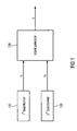
- FIG. 1 illustrates an apparatus for capturing audio information from a target location according to an embodiment
- FIG. 2 illustrates an apparatus according to an embodiment using two beamformers and a stage for computing the output signal
- FIG. 3 a illustrates a beamformer and a beam of the beamformer being directed towards a target location
- FIG. 3 b illustrates a beamformer and a beam of the beamformer showing further details
- FIG. 4 a illustrates a geometric setup of two beamformers with respect to a target location according to an embodiment
- FIG. 4 b depicts the geometric setup of the two beamformers of FIG. 4 a and three sound sources
- FIG. 4 c illustrates the geometric setup of the two beamformers of FIG. 4 b and three sound sources depicted in a more detailed illustration
- FIG. 5 depicts a signal generator according to an embodiment
- FIG. 6 illustrates a signal generator according to another embodiment
- FIG. 7 is a flow chart illustrating the generation of an audio output signal based on a cross-spectral density and on a power spectral density according to an embodiment.
- FIG. 1 illustrates an apparatus for capturing audio information from a target location.
- the apparatus comprises a first beamformer 110 being arranged in a recording environment and having a first recording characteristic.
- the apparatus comprises a second beamformer 120 being arranged in the recording environment and having a second recording characteristic.
- the apparatus comprises a signal generator 130 .
- the first beamformer 110 is configured for recording a first beamformer audio signal s 1 when the first beamformer 110 is directed towards the target location with respect to the first recording characteristic.
- the second beamformer 120 is configured for recording a second beamformer audio signal s 2 when the second beamformer 120 is directed towards the target location with respect to the second recording characteristic.
- the first beamformer 110 and the second beamformer 120 are arranged such that a first virtual straight line, being defined to pass through the first beamformer 110 and the target location, and a second virtual straight line, being defined to pass through the second beamformer 120 and the target location, are not parallel with respect to each other.
- the signal generator 130 is configured to generate an audio output signal s based on the first beamformer audio signal s 1 and on the second beamformer audio signal s 2 , so that the audio output signal s reflects relatively more audio information from the target location compared to the audio information from the target location in the first and second beamformer audio signal s 1 , s 2 .
- FIG. 2 illustrates an apparatus according to an embodiment using two beamformers and a stage for computing the output signal as the common part of the two beamformer individual output signals.
- a signal generator 230 realizes the computation of the common signal part (an “acoustic intersection”).
- FIG. 3 a illustrates a beamformer 310 .
- the beamformer 310 of the embodiment of FIG. 3 a is an apparatus for directionally selective acquisition of spatial sound.
- the beamformer 310 may be a directional microphone or a microphone array.
- the beamformer may comprise a plurality of directional microphones.
- FIG. 3 a illustrates a curved line 316 that encloses a beam 315 . All points on the curved line 316 that defines the beam 315 are characterized in that a predefined sound pressure level originating from a point on the curved line results in the same signal level output of the microphone for all points on the curved line.
- FIG. 3 a illustrates a major axis 320 of the beamformer.
- the major axis 320 of the beamformer 310 is defined in that a sound with a predefined sound pressure level originating from a considered point on the major axis 320 results in a first signal level output in the beamformer that is greater than or equal to a second signal level output of the beamformer resulting from a sound with the predefined sound pressure level originating from any other point having the same distance from the beamformer as the considered point.
- FIG. 3 b illustrates this in more detail.
- the points 325 , 326 and 327 have equal distance d from the beamformer 310 .
- a sound with a predefined sound pressure level originating from the point 325 on the major axis 320 results in a first signal level output in the beamformer that is greater than or equal to a second signal level output of the beamformer resulting from a sound with the predefined sound pressure level originating from, for example, point 326 or point 327 , which have the same distance d from the beamformer 310 as the point 325 on the major axis.
- the major axis indicates the point on a virtual ball with the beamformer located in the center of the ball, which generates the greatest signal level output in the beamformer when a predefined sound pressure level originates from the point compared with any other point on the virtual ball.
- the target location 330 may be a location from which sounds originate that a user intends to record using the beamformer 310 .
- the beamformer may be directed to the target location to record the desired sound.
- a beamformer 310 is considered to be directed to a target location 330 , when the major axis 320 of the beamformer 310 passes through the target location 330 .
- the target location 330 may be a target area while in other examples, the target location may be a point.
- the major axis 320 is considered to pass through the target location 330 , when the point is located on the major axis 320 .
- the major axis 320 of the beamformer 310 passes through the target location 330 , and therefore, the beamformer 310 is directed to the target location.
- the beamformer 310 has a recording characteristic that indicates the ability of the beamformer to record sound depending on the direction the sound originates from.
- the recording characteristic of the beamformer 310 comprises the direction of the major axis 320 in space, the direction, form and properties of the beam 315 , etc.
- FIG. 4 a illustrates a geometric setup of two beamformers, a first beamformer 410 and a second beamformer 420 , with respect to a target location 430 .
- a first beam 415 of the first beamformer 410 and a second beam 425 of the second beamformer 420 are illustrated.
- FIG. 4 a depicts a first major axis 418 of the first beamformer 410 and a second major axis 428 of the second beamformer 420 .
- the first beamformer 410 is arranged such that it is directed to the target location 430 , as the first major axis 418 passes through the target location 430 .
- the second beamformer 420 is also directed to the target location 430 , as the second major axis 428 passes through the target location 430 .
- the first beam 415 of the first beamformer 410 and the second beam 425 of the second beamformer 420 intersect in the target location 430 , where a target source that outputs sound is located.
- An angle of intersection of the first major axis 418 of the first beamformer 410 and the second major axis 428 of the second beamformer 420 is denoted as ⁇ .
- the angle of intersection ⁇ is 90 degrees. In other embodiments, the angle of intersection is between 30 degrees and 150 degrees.
- the first major axis and the second virtual major axis intersect and define a plane that can be arbitrarily oriented.
- FIG. 4 b depicts the geometric setup of the two beamformers of FIG. 4 a , further illustrating three sound sources src 1 , src 2 , src 3 .
- the beams 415 , 425 of beamformers 410 and 420 intersect in the target location, i.e. the location of the target source src 3 .
- the source src 1 and the source src 2 are located on one of the two beams 415 , 425 only.
- the first and the second beamformers 410 , 420 are adapted for directionally selective sound acquisition and their beams 415 , 425 indicate the sound that is acquired by them, respectively.
- the first beam 425 of the first beamformer indicates a first recording characteristic of the first beamformer 410 .
- the second beam 425 of the second beamformer 420 indicates a second recording characteristic of the second beamformer 420 .
- the sources src 1 and src 2 represent undesired sources that interfere with the signal of the desired source src 3 .
- sources src 1 and src 2 may also be considered as the independent ambience components picked up by the two beamformers.
- the output of an apparatus according to an embodiment would only return src 3 while fully suppressing the undesired sources src 1 and src 2 .
- two or even more devices for directionally selective sound acquisition e.g. directional microphones, microphone arrays and corresponding beamformers
- Suitable beamformers may, for example, be microphone arrays or highly directional microphones, such as shot-gun microphones, and the output signals of, e.g., the microphone arrays or the highly directional microphones may be employed as beamformer audio signals.
- “Remote spot microphone” functionality is used to pick up only sound originating from a constrained area around the spot.
- FIG. 4 c illustrates this in more detail.
- the first beamformer 410 captures sound from a first direction.
- the second beamformer 420 which is located quite distantly from the first beamformer 410 , captures sound from a second direction.
- the first and the second beamformer 410 , 420 are arranged such that they are directed to the target location 430 .
- the beamformers 410 , 420 e.g. two microphone arrays, are distant from each other and face the target spot from different directions. This is different to traditional microphone array processing, where only a single array is used and its different sensors are placed in close proximity of each other.
- the first major axis 418 of the first beamformer 410 and the second major axis 428 of the second beamformer 420 form two straight lines which are not arranged in parallel, but which instead intersect with an angle of intersection ⁇ .
- the second beamformer 420 would be optimally positioned with respect to the first beamformer, when the angle of intersection is 90 degrees. In embodiments, the angle of intersection is at least 60 degrees.
- the target spot or target area for sound capture is the intersection of both beams 415 , 425 .
- the signal from this area is derived by processing the output signals of the two beamformers 410 , 420 , such that an “acoustic intersection” is computed. This intersection can be considered as the signal part that is common/coherent between the two individual beamformer output signals.
- Such a concept exploits both the individual directionality of the beamformers and the coherence between the beamformer output signals. This is different to common microphone array processing, where only a single array is used and its different sensors are placed in close proximity of each other.
- the concepts according to embodiments can be implemented with both classical beamformers and parametric spatial filters. If the beamformer introduces frequency-dependent amplitude and phase distortions, this should be known and taken into account for the computation of the “acoustic intersection”.
- a device e.g. a signal generator, computes an “acoustic intersection” component.
- An ideal device for computing the intersection would deliver full output, if a signal is present in both beamformer audio signals (e.g. the audio signals recorded by the first and the second beamformer) and it would deliver zero output, if a signal is present only in one or none of the two beamformer audio signals.
- a good suppression characteristics that also ensures a good performance of the device may, for example, be achieved, by determining the transfer gain of a signal only present in one beamformer audio signal and by setting it into relation to the transfer gain for a signal present in both beamformer audio signals.
- f 2 (x) can be set to identity without loss in generality.
- the “intersection component” may be implemented, in different ways.
- the common part between the two signals is computed using filters, e.g. classic adaptive LMS (Least Mean Square) filters, as they are common for acoustic echo cancellation.
- filters e.g. classic adaptive LMS (Least Mean Square) filters, as they are common for acoustic echo cancellation.
- FIG. 5 illustrates a signal generator according to an embodiment, wherein a common signal is computed from signals s 1 and s 2 using an adaptive filter 510 .
- the signal generator of FIG. 5 receives the first beamformer audio signal s 1 and the second beamformer audio signal s 2 and generates the audio output signal based on the first and the second beamformer audio signal s 1 and s 2 .
- the signal generator of FIG. 5 comprises an adaptive filter 510 .
- a classic minimum mean square error adaption/optimization processing scheme as known from acoustic echo cancellation, is realized by the adaptive filter 510 .
- the adaptive filter 510 receives a first beamformer audio signal s 1 and filters the first beamformer audio signal s 1 to generate a filtered first beamformer audio signal s as audio output signal. (Another suitable notation for s would be ⁇ tilde over (s) ⁇ , however, for better readability, the time-domain audio output signal will be referred to as “s” in the following). Filtering of the first beamformer audio signal s 1 is conducted based on adjustable filter coefficients of the adaptive filter 510 .
- the signal generator of FIG. 5 outputs the filtered first beamformer audio signal s. Moreover, the filtered beamformer audio output signal s is also fed into a difference calculator 520 . The difference calculator 520 also receives the second beamformer audio signal and calculates the difference between the filtered first beamformer audio signal s and the second beamformer audio signal s 2 .
- the signal s i.e. the filtered version of s 1
- the signal s can be considered as representing the desired coherent output signal.
- the signal s i.e. the filtered version of s 1 represents the desired coherent output signal.
- the common part between the two signals is extracted based on a coherence metric between the two signals, see, for example, the coherence metrics described in
- a coherent part of two signals can be extracted from signals being represented in a time domain, but also, and advantageously, from signals being represented in a spectral domain, e.g. a time/frequency domain.
- FIG. 6 illustrates a signal generator according to an embodiment.
- the signal generator comprises an analysis filterbank 610 .
- the analysis filterbank 610 receives a first beamformer audio signal s 1 (t) and a second beamformer audio signal s 2 (t).
- the first and the second beamformer audio signal s 1 (t), s 2 (t) are represented in a time domain; t specifies the number of the time sample of the respective beamformer audio signal.
- the analysis filterbank 610 is adapted to transform the first and the second beamformer audio signal s 1 (t), s 2 (t) from a time domain into a spectral domain, e.g.
- the analysis filterbank may be any kind of analysis filterbank, such as Short-Time Fourier Transform (STFT) analysis filterbanks, polyphase filterbanks, Quadrature Mirror Filter (QMF) filterbanks, but also filterbanks like Discrete Fourier Transform (DFT), Discrete Cosine Transform (DCT) and the Modified Discrete Cosine Transform (MDCT) analysis filterbanks.
- STFT Short-Time Fourier Transform
- QMF Quadrature Mirror Filter
- DFT Discrete Fourier Transform
- DCT Discrete Cosine Transform
- MDCT Modified Discrete Cosine Transform
- the signal generator comprises an intersection calculator 620 for generating an audio output signal in the spectral domain.
- the signal generator comprises a synthesis filterbank 630 for transforming the generated audio output signal from a spectral domain to a time domain.
- the synthesis filterbank 630 may, for example, comprise Short-Time Fourier Transform (STFT) synthesis filterbanks, polyphase synthesis filterbanks, Quadrature Mirror Filter (QMF) synthesis filterbanks, but also synthesis filterbanks like Discrete Fourier Transform (DFT), Discrete Cosine Transform (DCT) and the Modified Discrete Cosine Transform (MDCT) synthesis filterbanks.
- STFT Short-Time Fourier Transform
- QMF Quadrature Mirror Filter
- DFT Discrete Fourier Transform
- DCT Discrete Cosine Transform
- MDCT Modified Discrete Cosine Transform
- intersection calculator 620 of FIG. 6 may be adapted to compute the audio output signal in the spectral domain according to one or more of these ways.
- the coherence is a measure of the common coherent content while compensating for scaling and phase shift operations. See, for example:
- One possibility to generate an estimate of the coherent signal part of the first and the second beamformer audio signal is to apply the cross-factors to one of the two signals.
- the cross-factors may be time-averaged.
- the signals S 1 (k,n) and S 2 (k,n) denote spectral-domain representations of the beamformer audio signals where k is a frequency index and n is a time index. For each particular time-frequency tile (k,n) specified by a particular frequency index k and a particular time index n, a coefficient exists for each of the signals S 1 (k,n) and S 2 (k,n). From the two spectral-domain beamformer audio signals S 1 (k,n), S 2 (k,n), the intersection component energy is computed.
- the superscript * denotes the conjugate of a complex number and E ⁇ ⁇ represents mathematical expectation.
- the expectation operator is replaced, e.g., by temporal or frequency smoothing of the term S 1 (k,n) ⁇ S* 2 (k,n), depending on the time/frequency resolution of the filterbank employed.
- 2 ⁇ P 2 ( k,n ) E ⁇
- a first way to obtain an output signal is based on modifying the first beamformer audio signal S 1 (k,n):
- an alternative output signal can be derived from the second beamformer audio signal S 2 (k,n):
- the maximum value of the gain functions G 1 (k,n) and G 2 (k,n) may be useful to limit the maximum value of the gain functions G 1 (k,n) and G 2 (k,n) to a certain threshold value, e.g. to one.
- FIG. 7 is a flow chart illustrating the generation of an audio output signal based on a cross spectral density and on a power spectral density according to an embodiment.
- a cross-spectral density C 12 (k, n) of the first and the second beamformer audio signal is computed.
- C 12 (k,n)
- may be applied.
- step 720 the power spectral density P 1 (k, n) of the first beamformer audio signal is computed.
- the power spectral density of the second beamformer audio signal may be used as well.
- a gain function G 1 ( k, n ) is computed based on the cross-spectral density calculated in step 710 and the power spectral density calculated in step 720 .
- the first beamformer audio signal S 1 (k, n) is modified to obtain desired the audio output signal Y 1 (k, n). If the power spectral density of the second beamformer audio signal has been calculated in step 720 , then, the second beamformer audio signal S 2 (k, n) may be modified to obtain the desired audio output signal.
- An output signal may be obtained by applying the formula
- the gain functions will take small values in case the recorded sound in the beamformer audio signals does not comprise signal components of the acoustic intersection. On the other hand, gain values close to one are obtained if the beamformer audio signals correspond to the desired acoustic intersection.
- the final output signal as the smaller signal (by energy) of Y 1 and Y 2 (or Y 3 and Y 4 ), respectively.
- the signal Y 1 or Y 2 of the two signals Y 1 , Y 2 is considered as the smaller signal, that has the smaller average energy.
- the signal Y 3 or Y 4 is considered as the smaller signal of both signals Y 3 , Y 4 , that has the smaller average energy.
- the spectral-domain audio output signal S may be converted back from a time/frequency representation to a time signal by using a synthesis (inverse) filterbank.
- the common part between the two signals is extracted by processing the magnitude spectra of a combined signal (e.g. a sum signal), for example, such that it has the intersection (e.g. minimum) PSD (Power Spectral Density) of both (normalized) beamformer signals.
- PSD Power Spectral Density
- the input signals may be analyzed in a time/frequency selective fashion, as described before, and an idealized assumption is made that the two noise signals are sparse and disjoint, i.e. do not appear at the same time/frequency tile.
- a simple solution would be to limit the Power Spectral Density (PSD) value of one of the signals to the value of the other signal after some suitable re-normalization/alignment procedure. It may be assumed that the relative delay between the two signals is limited such that it is substantially smaller than the filterbank window size.
- aspects have been described in the context of an apparatus, it is clear that these aspects also represent a description of the corresponding method, where a block or device corresponds to a method step or a feature of a method step. Analogously, aspects described in the context of a method step also represent a description of a corresponding block or item or feature of a corresponding apparatus.
- a signal generated according to the above-described embodiments can be stored on a digital storage medium or can be transmitted on a transmission medium such as a wireless transmission medium or a wired transmission medium such as the Internet.
- embodiments of the invention can be implemented in hardware or in software.
- the implementation can be performed using a digital storage medium, for example a floppy disk, a DVD, a CD, a ROM, a PROM, an EPROM, an EEPROM or a FLASH memory, having electronically readable control signals stored thereon, which cooperate (or are capable of cooperating) with a programmable computer system such that the respective method is performed.
- a digital storage medium for example a floppy disk, a DVD, a CD, a ROM, a PROM, an EPROM, an EEPROM or a FLASH memory, having electronically readable control signals stored thereon, which cooperate (or are capable of cooperating) with a programmable computer system such that the respective method is performed.
- Some embodiments according to the invention comprise a non-transitory data carrier having electronically readable control signals, which are capable of cooperating with a programmable computer system, such that one of the methods described herein is performed.
- embodiments of the present invention can be implemented as a computer program product with a program code, the program code being operative for performing one of the methods when the computer program product runs on a computer.
- the program code may for example be stored on a machine readable carrier.
- inventions comprise the computer program for performing one of the methods described herein, stored on a machine readable carrier.
- an embodiment of the inventive method is, therefore, a computer program having a program code for performing one of the methods described herein, when the computer program runs on a computer.
- a further embodiment of the inventive methods is, therefore, a data carrier (or a digital storage medium, or a computer-readable medium) comprising, recorded thereon, the computer program for performing one of the methods described herein.
- a further embodiment of the inventive method is, therefore, a data stream or a sequence of signals representing the computer program for performing one of the methods described herein.
- the data stream or the sequence of signals may for example be configured to be transferred via a data communication connection, for example via the Internet.
- a further embodiment comprises a processing means, for example a computer, or a programmable logic device, configured to or adapted to perform one of the methods described herein.
- a processing means for example a computer, or a programmable logic device, configured to or adapted to perform one of the methods described herein.
- a further embodiment comprises a computer having installed thereon the computer program for performing one of the methods described herein.
- a programmable logic device for example a field programmable gate array
- a field programmable gate array may cooperate with a microprocessor in order to perform one of the methods described herein.
- the methods are advantageously performed by any hardware apparatus.
Landscapes
- Health & Medical Sciences (AREA)
- Otolaryngology (AREA)
- Physics & Mathematics (AREA)
- Engineering & Computer Science (AREA)
- Acoustics & Sound (AREA)
- Signal Processing (AREA)
- General Health & Medical Sciences (AREA)
- Circuit For Audible Band Transducer (AREA)
- Obtaining Desirable Characteristics In Audible-Bandwidth Transducers (AREA)
- Measurement Of Velocity Or Position Using Acoustic Or Ultrasonic Waves (AREA)
- Stereophonic System (AREA)
Abstract
Description
- [Ea01] Eargle J. “The Microphone Book” Focal press 2001.
- [BW01] M. Brandstein, D. Ward: “Microphone Arrays—Signal Processing Techniques and Applications”, Springer Berlin, 2001, ISBN: 978-3-540-41953-2.
- [Elk00] G. W. Elko: “Superdirectional microphone arrays” in S. G. Gay, J. Benesty (eds.): “Acoustic Signal Processing for Telecommunication”, Chapter 10, Kluwer Academic Press, 2000, ISBN: 978-0792378143.
- [BS01]: J. Bitzer, K. U. Simmer: “Superdirective microphone arrays” in M. Brandstein, D. Ward (eds.): “Microphone Arrays—Signal Processing Techniques and Applications”,
Chapter 2, Springer Berlin, 2001, ISBN: 978-3-540-41953-2.
- [CBH06] J. Chen, J. Benesty, Y. Huang: “Time Delay Estimation in Room Acoustic Environments: An Overview”, EURASIP Journal on Applied Signal Processing, Article ID 26503, Volume 2006 (2006).
- [DiFi2009] M. Kallinger, G. Del Galdo, F. Küch, D. Mahne, and R. Schultz-Amling, “Spatial Filtering using Directional Audio Coding Parameters,” in Proc. IEEE Int. Conf. on Acoustics, Speech, and Signal Processing (ICASSP), April 2009,
and is implemented in the parameters domain of Directional Audio Coding (DirAC), an efficient spatial coding technique. Directional Audio Coding is described in - [Pu106] Pulkki, V., “Directional audio coding in spatial sound reproduction and stereo upmixing,” in Proceedings of The AES 28th International Conference, pp. 251-258, PiteA, Sweden, Jun. 30-Jul. 2, 2006.
- [Vil06] L. Villemoes, J. Herre, J. Breebaart, G. Hotho, S. Disch, H. Purnhagen, and K. Kjörling, “MPEG Surround: The Forthcoming ISO Standard for Spatial Audio Coding,” in AES 28th International Conference, Pitea, Sweden, June 2006.
- [Fa108] C. Faller: “Obtaining a Highly Directive Center Channel from Coincident Stereo Microphone Signals”, Proc. 124th AES convention, Amsterdam, The Netherlands, 2008, Preprint 7380.
- [SBM01] K. U. Simmer, J. Bitzer, and C. Marro: “Post-Filtering Techniques” in M. Brandstein, D. Ward (eds.): “Microphone Arrays—Signal Processing Techniques and Applications”, Chapter 3, Springer Berlin, 2001, ISBN: 978-3-540-41953-2,
a family of systems is described, which employ at least two (not necessarily directional) microphones and a processing of their output signal is based on the coherence of the signals. The underlying assumption is that diffuse background noise will appear as incoherent parts in the two microphone signals, whereas a source signal will appear coherently in these signals. Based on this premise, the coherent part is extracted as source signal. Techniques mentioned in [SBM01] were developed due to the fact that filter-and-sum beamformers with a limited number of microphones are hardly capable of reducing diffuse noise signals. No assumptions on the location of the microphones are made; not even the spacing of microphones needs to be known.
wherein Y1(k, n) is the audio output signal in the spectral domain, wherein S1(k, n) is the first beamformer audio signal, wherein C12(k, n) is a cross-spectral density of the first and the second beamformer audio signal, and wherein P1(k, n) is a power spectral density of the first beamformer audio signal, or
by employing the formula
wherein Y2(k, n) is the audio output signal in the spectral domain, wherein S2(k, n) is the second beamformer audio signal, wherein C12(k, n) is a cross-spectral density of the first and the second beamformer audio signal, and wherein P2(k, n) is a power spectral density of the second beamformer audio signal.
wherein Y3(k, n) is the audio output signal in the spectral domain, wherein S1 is the first beamformer audio signal, wherein C12(k, n) is a cross-spectral density of the first beamformer audio signal, wherein P1(k, n) is a power spectral density of the first beamformer audio signal, and wherein P2(k, n) is a power spectral density of the second beamformer audio signal, or by employing the formula
wherein Y4(k, n) is the audio output signal in the spectral domain, wherein S2 is the second beamformer audio signal, wherein C12(k, n) is a cross-spectral density of the first and the second beamformer audio signal, wherein P1(k, n) is a power spectral density of the first beamformer audio signal, and wherein P2(k, n) is a power spectral density of the second beamformer audio signal.
s 1 =f 1(s)+n 1
and
s 2 =f 2(s)+n 2
where f1(x) and f2(x) are the individual filtering, delay and/or scaling functions present for the two signals. Thus, the task is to estimate s from s1=f1(s)+n1 and s2=f2(s)+n2. To avoid ambiguities, f2(x) can be set to identity without loss in generality.
- [Fa03] C. Faller and F. Baumgarte, “Binaural Cue Coding—Part II: Schemes and applications,” IEEE Trans. on Speech and Audio Proc., vol. 11, no. 6, November 2003.
- [Fa06] C. Faller, “Parametric Multichannel Audio Coding: Synthesis of Coherence Cues,” IEEE Trans. on Speech and Audio Proc., vol. 14, no. 1, January 2006;
- [Her08] J. Herre, K. Kjörling, J. Breebaart, C. Faller, S. Disch, H. Purnhagen, J. Koppens, J. Hilpert, J. Rödén. W. Oomen, K. Linzmeier, K. S. Chong: “MPEG Surround—The ISO/MPEG Standard for Efficient and Compatible Multichannel Audio Coding”, Journal of the AES, Vol. 56, No. 11, November 2008, pp. 932-955
C 12(k,n)=|E{S 1(k,n)·S* 2(k,n)}|
P 1(k,n)=E{|S 1(k,n)|2}
P 2(k,n)=E{|S 2(k,n)|2}.
or by applying the formula:
- [BS01] J. Bitzer, K. U. Simmer: “Superdirective microphone arrays” in M. Brandstein, D. Ward (eds.): “Microphone Arrays—Signal Processing Techniques and Applications”,
Chapter 2, Springer Berlin, 2001, ISBN: 978-3-540-41953-2 - [BW01] M. Brandstein, D. Ward: “Microphone Arrays—Signal Processing Techniques and Applications”, Springer Berlin, 2001, ISBN: 978-3-540-41953-2
- [CBH06] J. Chen, J. Benesty, Y. Huang: “Time Delay Estimation in Room Acoustic Environments An Overview”, EURASIP Journal on Applied Signal Processing, Article ID 26503, Volume 2006 (2006)
- [Pul06] Pulkki, V., “Directional audio coding in spatial sound reproduction and stereo upmixing,” in Proceedings of The AES 28th International Conference, pp. 251-258, Piteå, Sweden, Jun. 30-Jul. 2, 2006.
- [DiFi2009] M. Kallinger, G. Del Galdo, F. Küch, D. Mahne, and R. Schultz-Amling, “Spatial Filtering using Directional Audio Coding Parameters,” in Proc. IEEE Int. Conf. on Acoustics, Speech, and Signal Processing (ICASSP), April 2009.
- [Ea01] Eargle J. “The Microphone Book” Focal press 2001.
- [Elk00] G. W. Elko: “Superdirectional microphone arrays” in S. G. Gay, J. Benesty (eds.): “Acoustic Signal Processing for Telecommunication”, Chapter 10, Kluwer Academic Press, 2000, ISBN: 978-0792378143
- [Fa03] C. Faller and F. Baumgarte, “Binaural Cue Coding—Part II: Schemes and applications,” IEEE Trans. on Speech and Audio Proc., vol. 11, no. 6, November 2003
- [Fa06] C. Faller, “Parametric Multichannel Audio Coding: Synthesis of Coherence Cues,” IEEE Trans. on Speech and Audio Proc., vol. 14, no. 1, January 2006
- [Fal08] C. Faller: “Obtaining a Highly Directive Center Channel from Coincident Stereo Microphone Signals”, Proc. 124th AES convention, Amsterdam, The Netherlands, 2008, Preprint 7380.
- [Her08] J. Herre, K. Kjörling, J. Breebaart, C. Faller, S. Disch, H. Purnhagen, J. Koppens, J. Hilpert, J. Rödén. W. Oomen, K. Linzmeier, K. S. Chong: “MPEG Surround—The ISO/MPEG Standard for Efficient and Compatible Multichannel Audio Coding”, Journal of the AES, Vol. 56, No. 11, November 2008, pp. 932-955
- [SBM01] K. U. Simmer, J. Bitzer, and C. Marro: “Post-Filtering Techniques” in M. Brandstein, D. Ward (eds.): “Microphone Arrays—Signal Processing Techniques and Applications”, Chapter 3, Springer Berlin, 2001, ISBN: 978-3-540-41953-2
- [Veen88] B. D. V. Veen and K. M. Buckley. “Beamforming: A versatile approach to spatial filtering”. IEEE ASSP Magazine, pages 4-24, April 1988.
- [Vil06] L. Villemoes, J. Herre, J. Breebaart, G. Hotho, S. Disch, H. Purnhagen, and K. Kjörling, “MPEG Surround: The Forthcoming ISO Standard for Spatial Audio Coding,” in AES 28th International Conference, Pitea, Sweden, June 2006.
Claims (13)
Priority Applications (1)
| Application Number | Priority Date | Filing Date | Title |
|---|---|---|---|
| US13/904,857 US9143856B2 (en) | 2010-12-03 | 2013-05-29 | Apparatus and method for spatially selective sound acquisition by acoustic triangulation |
Applications Claiming Priority (3)
| Application Number | Priority Date | Filing Date | Title |
|---|---|---|---|
| US41972010P | 2010-12-03 | 2010-12-03 | |
| PCT/EP2011/071600 WO2012072787A1 (en) | 2010-12-03 | 2011-12-02 | Apparatus and method for spatially selective sound acquisition by acoustic triangulation |
| US13/904,857 US9143856B2 (en) | 2010-12-03 | 2013-05-29 | Apparatus and method for spatially selective sound acquisition by acoustic triangulation |
Related Parent Applications (1)
| Application Number | Title | Priority Date | Filing Date |
|---|---|---|---|
| PCT/EP2011/071600 Continuation WO2012072787A1 (en) | 2010-12-03 | 2011-12-02 | Apparatus and method for spatially selective sound acquisition by acoustic triangulation |
Publications (2)
| Publication Number | Publication Date |
|---|---|
| US20130258813A1 US20130258813A1 (en) | 2013-10-03 |
| US9143856B2 true US9143856B2 (en) | 2015-09-22 |
Family
ID=45478269
Family Applications (1)
| Application Number | Title | Priority Date | Filing Date |
|---|---|---|---|
| US13/904,857 Active 2032-04-26 US9143856B2 (en) | 2010-12-03 | 2013-05-29 | Apparatus and method for spatially selective sound acquisition by acoustic triangulation |
Country Status (14)
| Country | Link |
|---|---|
| US (1) | US9143856B2 (en) |
| EP (1) | EP2647221B1 (en) |
| JP (1) | JP2014502108A (en) |
| KR (1) | KR101555416B1 (en) |
| CN (1) | CN103339961B (en) |
| AR (1) | AR084090A1 (en) |
| AU (1) | AU2011334840B2 (en) |
| BR (1) | BR112013013673B1 (en) |
| CA (1) | CA2819393C (en) |
| ES (1) | ES2779198T3 (en) |
| MX (1) | MX2013006069A (en) |
| RU (1) | RU2559520C2 (en) |
| TW (1) | TWI457011B (en) |
| WO (1) | WO2012072787A1 (en) |
Families Citing this family (34)
| Publication number | Priority date | Publication date | Assignee | Title |
|---|---|---|---|---|
| ES2779198T3 (en) * | 2010-12-03 | 2020-08-14 | Fraunhofer-Gesellschaft zur Förderung der Angewandten Forschung Ev | Apparatus and procedure for spatially selective acquisition of sound using acoustic triangulation |
| EP2984852B1 (en) * | 2013-04-08 | 2021-08-04 | Nokia Technologies Oy | Method and apparatus for recording spatial audio |
| JP6106571B2 (en) * | 2013-10-16 | 2017-04-05 | 日本電信電話株式会社 | Sound source position estimating apparatus, method and program |
| CN104715753B (en) * | 2013-12-12 | 2018-08-31 | 联想(北京)有限公司 | A kind of method and electronic equipment of data processing |
| US9961456B2 (en) * | 2014-06-23 | 2018-05-01 | Gn Hearing A/S | Omni-directional perception in a binaural hearing aid system |
| US9326060B2 (en) * | 2014-08-04 | 2016-04-26 | Apple Inc. | Beamforming in varying sound pressure level |
| DE102015203600B4 (en) * | 2014-08-22 | 2021-10-21 | Fraunhofer-Gesellschaft zur Förderung der angewandten Forschung e.V. | FIR filter coefficient calculation for beamforming filters |
| US10283139B2 (en) | 2015-01-12 | 2019-05-07 | Mh Acoustics, Llc | Reverberation suppression using multiple beamformers |
| US10460744B2 (en) * | 2016-02-04 | 2019-10-29 | Xinxiao Zeng | Methods, systems, and media for voice communication |
| RU2630161C1 (en) * | 2016-02-18 | 2017-09-05 | Закрытое акционерное общество "Современные беспроводные технологии" | Sidelobe suppressing device for pulse compression of multiphase codes p3 and p4 (versions) |
| JP6260666B1 (en) * | 2016-09-30 | 2018-01-17 | 沖電気工業株式会社 | Sound collecting apparatus, program and method |
| JP2018170617A (en) * | 2017-03-29 | 2018-11-01 | 沖電気工業株式会社 | Sound pickup device, program, and method |
| JP6763332B2 (en) * | 2017-03-30 | 2020-09-30 | 沖電気工業株式会社 | Sound collectors, programs and methods |
| WO2018187859A1 (en) * | 2017-04-11 | 2018-10-18 | Systèmes De Contrôle Actif Soft Db Inc. | A system and a method for noise discrimination |
| US10789949B2 (en) * | 2017-06-20 | 2020-09-29 | Bose Corporation | Audio device with wakeup word detection |
| JP2019021966A (en) * | 2017-07-11 | 2019-02-07 | オリンパス株式会社 | Sound collecting device and sound collecting method |
| CN108109617B (en) * | 2018-01-08 | 2020-12-15 | 深圳市声菲特科技技术有限公司 | Remote pickup method |
| WO2019222856A1 (en) * | 2018-05-24 | 2019-11-28 | Nureva Inc. | Method, apparatus and computer-readable media to manage semi-constant (persistent) sound sources in microphone pickup/focus zones |
| US10210882B1 (en) * | 2018-06-25 | 2019-02-19 | Biamp Systems, LLC | Microphone array with automated adaptive beam tracking |
| US10694285B2 (en) | 2018-06-25 | 2020-06-23 | Biamp Systems, LLC | Microphone array with automated adaptive beam tracking |
| JP7405758B2 (en) * | 2018-09-26 | 2023-12-26 | パナソニック インテレクチュアル プロパティ コーポレーション オブ アメリカ | Acoustic object extraction device and acoustic object extraction method |
| WO2020154802A1 (en) | 2019-01-29 | 2020-08-06 | Nureva Inc. | Method, apparatus and computer-readable media to create audio focus regions dissociated from the microphone system for the purpose of optimizing audio processing at precise spatial locations in a 3d space. |
| US10832695B2 (en) * | 2019-02-14 | 2020-11-10 | Microsoft Technology Licensing, Llc | Mobile audio beamforming using sensor fusion |
| DE102019205205B3 (en) * | 2019-04-11 | 2020-09-03 | BSH Hausgeräte GmbH | Interaction device |
| US11380312B1 (en) * | 2019-06-20 | 2022-07-05 | Amazon Technologies, Inc. | Residual echo suppression for keyword detection |
| US10820129B1 (en) * | 2019-08-15 | 2020-10-27 | Harman International Industries, Incorporated | System and method for performing automatic sweet spot calibration for beamforming loudspeakers |
| US10735887B1 (en) * | 2019-09-19 | 2020-08-04 | Wave Sciences, LLC | Spatial audio array processing system and method |
| US20200120416A1 (en) * | 2019-12-16 | 2020-04-16 | Intel Corporation | Methods and apparatus to detect an audio source |
| EP4147230B1 (en) | 2020-05-08 | 2024-11-13 | Microsoft Technology Licensing, LLC | System and method for data augmentation for multi-microphone signal processing |
| US12342137B2 (en) | 2021-05-10 | 2025-06-24 | Nureva Inc. | System and method utilizing discrete microphones and virtual microphones to simultaneously provide in-room amplification and remote communication during a collaboration session |
| US12356146B2 (en) | 2022-03-03 | 2025-07-08 | Nureva, Inc. | System for dynamically determining the location of and calibration of spatially placed transducers for the purpose of forming a single physical microphone array |
| US12549917B2 (en) | 2022-03-22 | 2026-02-10 | Nureva, Inc. | System for dynamically forming a virtual microphone coverage map from a combined array to any dimension, size and shape based on individual microphone element locations |
| US12457465B2 (en) | 2022-03-28 | 2025-10-28 | Nureva, Inc. | System for dynamically deriving and using positional based gain output parameters across one or more microphone element locations |
| JP7380783B1 (en) | 2022-08-29 | 2023-11-15 | 沖電気工業株式会社 | Sound collection device, sound collection program, sound collection method, determination device, determination program, and determination method |
Citations (12)
| Publication number | Priority date | Publication date | Assignee | Title |
|---|---|---|---|---|
| JPH1124690A (en) | 1997-07-01 | 1999-01-29 | Sanyo Electric Co Ltd | Speaker voice extractor |
| JP2001204092A (en) | 2000-01-18 | 2001-07-27 | Nippon Telegr & Teleph Corp <Ntt> | Zone-specific sound pickup device |
| US20040193430A1 (en) | 2002-12-28 | 2004-09-30 | Samsung Electronics Co., Ltd. | Method and apparatus for mixing audio stream and information storage medium thereof |
| JP2004289762A (en) | 2003-01-29 | 2004-10-14 | Toshiba Corp | Audio signal processing method and apparatus and program |
| WO2006006935A1 (en) | 2004-07-08 | 2006-01-19 | Agency For Science, Technology And Research | Capturing sound from a target region |
| WO2007025033A2 (en) | 2005-08-26 | 2007-03-01 | Step Communications Corporation | Method and system for enhancing regional sensitivity noise discrimination |
| US20080260175A1 (en) | 2002-02-05 | 2008-10-23 | Mh Acoustics, Llc | Dual-Microphone Spatial Noise Suppression |
| JP2009135594A (en) | 2007-11-28 | 2009-06-18 | Panasonic Electric Works Co Ltd | Acoustic input device |
| US20100014690A1 (en) | 2008-07-16 | 2010-01-21 | Nuance Communications, Inc. | Beamforming Pre-Processing for Speaker Localization |
| EP2154677A1 (en) | 2008-08-13 | 2010-02-17 | Fraunhofer-Gesellschaft zur Förderung der angewandten Forschung e.V. | An apparatus for determining a converted spatial audio signal |
| CN101843118A (en) | 2007-10-16 | 2010-09-22 | 峰力公司 | Method and system for wireless hearing aids |
| US20130258813A1 (en) * | 2010-12-03 | 2013-10-03 | Friedrich-Alexander-Universitaet Erlangen- Nuernberg | Apparatus and method for spatially selective sound acquisition by acoustictriangulation |
Family Cites Families (2)
| Publication number | Priority date | Publication date | Assignee | Title |
|---|---|---|---|---|
| DE10333395A1 (en) * | 2003-07-16 | 2005-02-17 | Alfred Kärcher Gmbh & Co. Kg | Floor Cleaning System |
| BRPI0913460B1 (en) * | 2008-09-11 | 2024-03-05 | Fraunhofer-Gesellschaft zur Förderung der angewandten Forschung e.V. | APPARATUS AND METHOD FOR PROVIDING A SET OF SPATIAL INDICATORS ON THE BASIS OF A MICROPHONE SIGNAL AND APPARATUS FOR PROVIDING A TWO-CHANNEL AUDIO SIGNAL AND A SET OF SPATIAL INDICATORS |
-
2011
- 2011-12-02 ES ES11808175T patent/ES2779198T3/en active Active
- 2011-12-02 AR ARP110104508 patent/AR084090A1/en active IP Right Grant
- 2011-12-02 WO PCT/EP2011/071600 patent/WO2012072787A1/en not_active Ceased
- 2011-12-02 TW TW100144362A patent/TWI457011B/en active
- 2011-12-02 BR BR112013013673-1A patent/BR112013013673B1/en active IP Right Grant
- 2011-12-02 MX MX2013006069A patent/MX2013006069A/en active IP Right Grant
- 2011-12-02 KR KR1020137016895A patent/KR101555416B1/en active Active
- 2011-12-02 AU AU2011334840A patent/AU2011334840B2/en active Active
- 2011-12-02 CA CA2819393A patent/CA2819393C/en active Active
- 2011-12-02 RU RU2013130227/28A patent/RU2559520C2/en active
- 2011-12-02 EP EP11808175.1A patent/EP2647221B1/en active Active
- 2011-12-02 CN CN201180066800.8A patent/CN103339961B/en active Active
- 2011-12-02 JP JP2013541372A patent/JP2014502108A/en active Pending
-
2013
- 2013-05-29 US US13/904,857 patent/US9143856B2/en active Active
Patent Citations (15)
| Publication number | Priority date | Publication date | Assignee | Title |
|---|---|---|---|---|
| JPH1124690A (en) | 1997-07-01 | 1999-01-29 | Sanyo Electric Co Ltd | Speaker voice extractor |
| JP2001204092A (en) | 2000-01-18 | 2001-07-27 | Nippon Telegr & Teleph Corp <Ntt> | Zone-specific sound pickup device |
| US20080260175A1 (en) | 2002-02-05 | 2008-10-23 | Mh Acoustics, Llc | Dual-Microphone Spatial Noise Suppression |
| RU2315371C2 (en) | 2002-12-28 | 2008-01-20 | Самсунг Электроникс Ко., Лтд. | Method and device for mixing an audio stream and information carrier |
| US20040193430A1 (en) | 2002-12-28 | 2004-09-30 | Samsung Electronics Co., Ltd. | Method and apparatus for mixing audio stream and information storage medium thereof |
| JP2004289762A (en) | 2003-01-29 | 2004-10-14 | Toshiba Corp | Audio signal processing method and apparatus and program |
| WO2006006935A1 (en) | 2004-07-08 | 2006-01-19 | Agency For Science, Technology And Research | Capturing sound from a target region |
| US20070047742A1 (en) * | 2005-08-26 | 2007-03-01 | Step Communications Corporation, A Nevada Corporation | Method and system for enhancing regional sensitivity noise discrimination |
| WO2007025033A2 (en) | 2005-08-26 | 2007-03-01 | Step Communications Corporation | Method and system for enhancing regional sensitivity noise discrimination |
| CN101843118A (en) | 2007-10-16 | 2010-09-22 | 峰力公司 | Method and system for wireless hearing aids |
| US20100278366A1 (en) | 2007-10-16 | 2010-11-04 | Phonak Ag | Method and system for wireless hearing assistance |
| JP2009135594A (en) | 2007-11-28 | 2009-06-18 | Panasonic Electric Works Co Ltd | Acoustic input device |
| US20100014690A1 (en) | 2008-07-16 | 2010-01-21 | Nuance Communications, Inc. | Beamforming Pre-Processing for Speaker Localization |
| EP2154677A1 (en) | 2008-08-13 | 2010-02-17 | Fraunhofer-Gesellschaft zur Förderung der angewandten Forschung e.V. | An apparatus for determining a converted spatial audio signal |
| US20130258813A1 (en) * | 2010-12-03 | 2013-10-03 | Friedrich-Alexander-Universitaet Erlangen- Nuernberg | Apparatus and method for spatially selective sound acquisition by acoustictriangulation |
Non-Patent Citations (17)
| Title |
|---|
| Bitzer, J. et al., "Superdirective Microphone Arrays", Brandstein, M., Ward, D., Edition: Microphone Arrays-Signal Processing Techniques and Applications, Springer Berlin, 2001, Chapter 2, pp. 19-38; ISBN: 978-3-540-41953-2. |
| Chen, J. et al., "Time Delay Estimation in Room Acoustic Environments: An Overview", EURASIP Journal on Applied Signal Processing, vol. 2006, Article 26503, pp. 1-19., 2006. |
| Chien, et al., "Car Speech Enhancement Using Microphone Array Beamforming and Post Filters", Proc. of the 9th Int'l Conf. on Speech Science & Technology, Melbourne, Dec. 2002, pp. 568-573. |
| Eargle, J. , "The Pressure Microphone", The Microphone Book, Focal Press Chapter 3, pp. 22-25, 2001. |
| Elko, G.W., "Superdirectional Microphone Arrays", Editors: S.L. Gay and J. Benesty; Acoustic Signal Processing for Telecommunication; Kluwer Academic Publishers, Norwell, MA; Chapter 10, pp. 181-235, 2000. |
| Faller, Christof, "Parametric Multichannel Audio Coding: Synthesis of Coherence Cues", IEEE Trans. on Speech and Audio Proc., vol. 14, No. 1, pp. 299-310, Jan. 2006. |
| Faller, et al., "Binaural Cue Coding-Part II: Schemes and Applications", IEEE Transactions on Speech and Audio Processing, vol. 11, No. 6, pp. 520-531, Nov. 2003. |
| Faller, et al., "Obtaining a Highly Directive Center Channel from Coincident Stereo Microphone Signals", AES Convention Paper 7380, Presented at the 124th Convention, Amsterdam, The Netherlands, May 2008, 7 pages. |
| Greenberg, J. et al., "Microphone Array Hearing Aids", In M. Brandstein, D. Ward: "Microphone Arrays-Signal Processing Techniques and Applications", Springer Berlin, Part 3, Chapter 11, pp. 229-253, 2001, ISBN: 978-3-540-41953-2. |
| Herre, J. et al., "Mpeg Surround-The ISO/MPEG Standard for Efficient and Compatible Multichannel Audio Coding", J. Audio Eng. Soc., vol. 56, No. 11, pp. 932-955, Nov. 2008. |
| Kallinger, Markus et al., "Spatial filtering using directional audio coding parameters", Acoustics, Speech and Signal Processing, XP031459205, Spatial Filtering using Directional Audio Coding Parameters, in Proc. IEEE Int. Conf. on Acoustics, Speech, and Signal Processing (ICASSP), pp. 217-220, Apr. 19, 2009. |
| Marro, et al., "Analysis of Noise Reduction and Derverberation Techniques Based on Microphone Arrays with Postfiltering", IEEE Transactions on Speech and Audio Processing, vol. 6 No. 3, New York, May 1998, pp. 240-259. |
| Pulkki, V., "Directional audio coding in spatial sound reproduction and stereo upmixing," in Proceedings of the AES 28th International Conference, pp. 251-258, Piteå, Sweden, Jun. 30-Jul. 2, 2006. |
| Simmer, et al., "Time Delay Compensation for Adaptive Multichannel Speech Enhancement Systems", Proc. of ISSSE-92, Paris, Sep. 1992, 4 pages. |
| Simmer, K. U. et al., "Post-Filtering Techniques", Springer Berlin, In M. Brandstein, D. Ward Enistion: Microphone Arrays-Signal Processing Techniques and Applications; Chapter 3; pp. 39-60, 2001, ISBN: 978-540-41953-2. |
| Veen, B.D.V. et al., "Beamforming: A versatile approach to spatial filtering", IEEE ASSP Magazine, pp. 4-24, Apr. 1988. |
| Villemoes, L. et al., "MPEG surround: The forthcoming ISO standard for spatial audio coding", in AES 28th International Conference, The Future of Audio Technology Surround and Beyond, pp. 1-18, Pitea, SE, Jul. 2, 2006. |
Also Published As
| Publication number | Publication date |
|---|---|
| CN103339961A (en) | 2013-10-02 |
| AR084090A1 (en) | 2013-04-17 |
| BR112013013673A2 (en) | 2017-09-26 |
| WO2012072787A1 (en) | 2012-06-07 |
| CN103339961B (en) | 2017-03-29 |
| RU2559520C2 (en) | 2015-08-10 |
| US20130258813A1 (en) | 2013-10-03 |
| AU2011334840B2 (en) | 2015-09-03 |
| EP2647221A1 (en) | 2013-10-09 |
| AU2011334840A1 (en) | 2013-07-04 |
| RU2013130227A (en) | 2015-01-10 |
| KR101555416B1 (en) | 2015-09-23 |
| TWI457011B (en) | 2014-10-11 |
| TW201234872A (en) | 2012-08-16 |
| EP2647221B1 (en) | 2020-01-08 |
| MX2013006069A (en) | 2013-10-30 |
| KR20130116299A (en) | 2013-10-23 |
| JP2014502108A (en) | 2014-01-23 |
| CA2819393C (en) | 2017-04-18 |
| ES2779198T3 (en) | 2020-08-14 |
| CA2819393A1 (en) | 2012-06-07 |
| BR112013013673B1 (en) | 2021-03-30 |
Similar Documents
| Publication | Publication Date | Title |
|---|---|---|
| US9143856B2 (en) | Apparatus and method for spatially selective sound acquisition by acoustic triangulation | |
| JP5814476B2 (en) | Microphone positioning apparatus and method based on spatial power density | |
| CA2819394C (en) | Sound acquisition via the extraction of geometrical information from direction of arrival estimates | |
| Priyanka | A review on adaptive beamforming techniques for speech enhancement | |
| Comminiello et al. | A novel affine projection algorithm for superdirective microphone array beamforming | |
| HK1190260B (en) | Apparatus and method for spatially selective sound acquisition by acoustic triangulation | |
| HK1190260A (en) | Apparatus and method for spatially selective sound acquisition by acoustic triangulation | |
| Magliocco | Distributed two-stage near-field beamforming using multiple differential microphone arrays | |
| Pedamallu | Microphone Array Wiener Beamforming with emphasis on Reverberation | |
| Yerramsetty | Microphone Array Wiener Beamformer and Speaker Localization With emphasis on WOLA Filter Bank | |
| HK1190490B (en) | Sound acquisition via the extraction of geometrical information from direction of arrival estimates |
Legal Events
| Date | Code | Title | Description |
|---|---|---|---|
| AS | Assignment |
Owner name: FRIEDRICH-ALEXANDER-UNIVERSITAET ERLANGEN-NUERNBER Free format text: ASSIGNMENT OF ASSIGNORS INTEREST;ASSIGNORS:HERRE, JUERGEN;KUECH, FABIAN;KALLINGER, MARKUS;AND OTHERS;SIGNING DATES FROM 20130729 TO 20130813;REEL/FRAME:031659/0469 Owner name: FRAUNHOFER-GESELLSCHAFT ZUR FOERDERUNG DER ANGEWAN Free format text: ASSIGNMENT OF ASSIGNORS INTEREST;ASSIGNORS:HERRE, JUERGEN;KUECH, FABIAN;KALLINGER, MARKUS;AND OTHERS;SIGNING DATES FROM 20130729 TO 20130813;REEL/FRAME:031659/0469 |
|
| STCF | Information on status: patent grant |
Free format text: PATENTED CASE |
|
| CC | Certificate of correction | ||
| MAFP | Maintenance fee payment |
Free format text: PAYMENT OF MAINTENANCE FEE, 4TH YEAR, LARGE ENTITY (ORIGINAL EVENT CODE: M1551); ENTITY STATUS OF PATENT OWNER: LARGE ENTITY Year of fee payment: 4 |
|
| AS | Assignment |
Owner name: FRAUNHOFER-GESELLSCHAFT ZUR FOERDERUNG DER ANGEWANDTEN FORSCHUNG E.V., GERMANY Free format text: ASSIGNMENT OF ASSIGNORS INTEREST;ASSIGNOR:FRIEDRICH-ALEXANDER-UNIVERSITAET ERLANGEN-NUERNBERG;REEL/FRAME:052726/0910 Effective date: 20191031 |
|
| MAFP | Maintenance fee payment |
Free format text: PAYMENT OF MAINTENANCE FEE, 8TH YEAR, LARGE ENTITY (ORIGINAL EVENT CODE: M1552); ENTITY STATUS OF PATENT OWNER: LARGE ENTITY Year of fee payment: 8 |