US9137066B2 - Method and apparatus for generating a metric for use in one or more of lock detection, SNR estimation, and modulation classification - Google Patents
Method and apparatus for generating a metric for use in one or more of lock detection, SNR estimation, and modulation classification Download PDFInfo
- Publication number
- US9137066B2 US9137066B2 US13/882,780 US201113882780A US9137066B2 US 9137066 B2 US9137066 B2 US 9137066B2 US 201113882780 A US201113882780 A US 201113882780A US 9137066 B2 US9137066 B2 US 9137066B2
- Authority
- US
- United States
- Prior art keywords
- metric
- received
- snr
- phase
- phase difference
- Prior art date
- Legal status (The legal status is an assumption and is not a legal conclusion. Google has not performed a legal analysis and makes no representation as to the accuracy of the status listed.)
- Active
Links
- 238000000034 method Methods 0.000 title claims abstract description 139
- 238000001514 detection method Methods 0.000 title claims abstract description 66
- 230000006870 function Effects 0.000 claims description 252
- 239000002243 precursor Substances 0.000 claims description 56
- 230000000295 complement effect Effects 0.000 claims description 45
- 238000012935 Averaging Methods 0.000 claims description 35
- 230000003321 amplification Effects 0.000 claims description 32
- 238000003199 nucleic acid amplification method Methods 0.000 claims description 32
- 230000010363 phase shift Effects 0.000 claims description 21
- 238000005070 sampling Methods 0.000 claims description 14
- 230000004044 response Effects 0.000 claims description 6
- 238000004364 calculation method Methods 0.000 description 24
- 238000013139 quantization Methods 0.000 description 19
- 230000008901 benefit Effects 0.000 description 9
- 238000004422 calculation algorithm Methods 0.000 description 8
- 238000006243 chemical reaction Methods 0.000 description 8
- 230000009467 reduction Effects 0.000 description 6
- 238000004088 simulation Methods 0.000 description 6
- 230000006978 adaptation Effects 0.000 description 5
- 238000004891 communication Methods 0.000 description 5
- 238000012986 modification Methods 0.000 description 5
- 230000004048 modification Effects 0.000 description 5
- 230000008569 process Effects 0.000 description 5
- 238000006467 substitution reaction Methods 0.000 description 5
- 102100026758 Serine/threonine-protein kinase 16 Human genes 0.000 description 4
- 101710184778 Serine/threonine-protein kinase 16 Proteins 0.000 description 4
- 230000009286 beneficial effect Effects 0.000 description 4
- 230000015556 catabolic process Effects 0.000 description 4
- 238000006731 degradation reaction Methods 0.000 description 4
- 238000010586 diagram Methods 0.000 description 4
- 238000012545 processing Methods 0.000 description 4
- 238000009825 accumulation Methods 0.000 description 3
- 230000006399 behavior Effects 0.000 description 3
- 230000014509 gene expression Effects 0.000 description 3
- 238000007792 addition Methods 0.000 description 2
- 238000004458 analytical method Methods 0.000 description 2
- 230000001364 causal effect Effects 0.000 description 2
- 238000005094 computer simulation Methods 0.000 description 2
- 230000003247 decreasing effect Effects 0.000 description 2
- 230000001934 delay Effects 0.000 description 2
- 230000001419 dependent effect Effects 0.000 description 2
- 238000013461 design Methods 0.000 description 2
- 238000012905 input function Methods 0.000 description 2
- 230000000737 periodic effect Effects 0.000 description 2
- 230000000717 retained effect Effects 0.000 description 2
- 238000012360 testing method Methods 0.000 description 2
- 229920000535 Tan II Polymers 0.000 description 1
- 230000003044 adaptive effect Effects 0.000 description 1
- 239000000654 additive Substances 0.000 description 1
- 230000000996 additive effect Effects 0.000 description 1
- 238000003491 array Methods 0.000 description 1
- 230000005540 biological transmission Effects 0.000 description 1
- 230000008859 change Effects 0.000 description 1
- 238000007635 classification algorithm Methods 0.000 description 1
- 230000001149 cognitive effect Effects 0.000 description 1
- 230000006835 compression Effects 0.000 description 1
- 238000007906 compression Methods 0.000 description 1
- 230000021615 conjugation Effects 0.000 description 1
- 238000012937 correction Methods 0.000 description 1
- 238000011161 development Methods 0.000 description 1
- 230000018109 developmental process Effects 0.000 description 1
- 238000009826 distribution Methods 0.000 description 1
- 230000000694 effects Effects 0.000 description 1
- 230000008570 general process Effects 0.000 description 1
- 238000007689 inspection Methods 0.000 description 1
- 238000009828 non-uniform distribution Methods 0.000 description 1
- 238000010606 normalization Methods 0.000 description 1
- 238000011160 research Methods 0.000 description 1
- 238000012827 research and development Methods 0.000 description 1
- 238000009738 saturating Methods 0.000 description 1
- 239000004065 semiconductor Substances 0.000 description 1
- 230000003595 spectral effect Effects 0.000 description 1
- 238000001228 spectrum Methods 0.000 description 1
- 230000009466 transformation Effects 0.000 description 1
- 230000005428 wave function Effects 0.000 description 1
Images

Classifications
-
- H—ELECTRICITY
- H04—ELECTRIC COMMUNICATION TECHNIQUE
- H04L—TRANSMISSION OF DIGITAL INFORMATION, e.g. TELEGRAPHIC COMMUNICATION
- H04L27/00—Modulated-carrier systems
- H04L27/18—Phase-modulated carrier systems, i.e. using phase-shift keying
- H04L27/20—Modulator circuits; Transmitter circuits
-
- H—ELECTRICITY
- H03—ELECTRONIC CIRCUITRY
- H03D—DEMODULATION OR TRANSFERENCE OF MODULATION FROM ONE CARRIER TO ANOTHER
- H03D13/00—Circuits for comparing the phase or frequency of two mutually-independent oscillations
-
- H—ELECTRICITY
- H03—ELECTRONIC CIRCUITRY
- H03J—TUNING RESONANT CIRCUITS; SELECTING RESONANT CIRCUITS
- H03J7/00—Automatic frequency control; Automatic scanning over a band of frequencies
- H03J7/02—Automatic frequency control
- H03J7/04—Automatic frequency control where the frequency control is accomplished by varying the electrical characteristics of a non-mechanically adjustable element or where the nature of the frequency controlling element is not significant
- H03J7/06—Automatic frequency control where the frequency control is accomplished by varying the electrical characteristics of a non-mechanically adjustable element or where the nature of the frequency controlling element is not significant using counters or frequency dividers
- H03J7/065—Automatic frequency control where the frequency control is accomplished by varying the electrical characteristics of a non-mechanically adjustable element or where the nature of the frequency controlling element is not significant using counters or frequency dividers the counter or frequency divider being used in a phase locked loop
-
- H04B17/009—
-
- H—ELECTRICITY
- H04—ELECTRIC COMMUNICATION TECHNIQUE
- H04B—TRANSMISSION
- H04B17/00—Monitoring; Testing
- H04B17/30—Monitoring; Testing of propagation channels
- H04B17/309—Measuring or estimating channel quality parameters
- H04B17/336—Signal-to-interference ratio [SIR] or carrier-to-interference ratio [CIR]
-
- H—ELECTRICITY
- H04—ELECTRIC COMMUNICATION TECHNIQUE
- H04B—TRANSMISSION
- H04B17/00—Monitoring; Testing
- H04B17/30—Monitoring; Testing of propagation channels
- H04B17/391—Modelling the propagation channel
-
- H—ELECTRICITY
- H04—ELECTRIC COMMUNICATION TECHNIQUE
- H04L—TRANSMISSION OF DIGITAL INFORMATION, e.g. TELEGRAPHIC COMMUNICATION
- H04L27/00—Modulated-carrier systems
- H04L27/32—Carrier systems characterised by combinations of two or more of the types covered by groups H04L27/02, H04L27/10, H04L27/18 or H04L27/26
- H04L27/34—Amplitude- and phase-modulated carrier systems, e.g. quadrature-amplitude modulated carrier systems
- H04L27/38—Demodulator circuits; Receiver circuits
- H04L27/3818—Demodulator circuits; Receiver circuits using coherent demodulation, i.e. using one or more nominally phase synchronous carriers
Definitions
- the present disclosure is directed at a method and apparatus for use in one or more of lock detection, signal-to-noise ratio (SNR) estimation, and modulation classification.
- SNR signal-to-noise ratio
- Digital communications systems often include one or more of a lock detector, a modulation classifier, and an SNR estimator.
- a lock detector is used, for example, when a receiver is coherently demodulating a carrier that it has received to determine whether a local carrier used for demodulation is in phase with the received carrier.
- a modulation classifier is used, for example, to determine which modulation scheme has been used to modulate the received carrier.
- Exemplary modulation schemes include various types of phase shift keying such as binary phase shift keying, quaternary phase shift keying, and more generally M-ary phase shift keying where M is theoretically any positive integer.
- An SNR estimator is used, for example, to estimate the SNR of the symbols transmitted using the received carrier.
- a method for generating a metric for one or both of lock detection and signal-to-noise ratio (SNR) estimation includes obtaining a baseband symbol from a received carrier that is modulated using the symbol according to a modulation order (M) equaling the number of distinct ideal symbol phases used to modulate the received carrier; determining a received phase of the symbol; and generating the metric from the received phase, wherein possible metrics depend on possible received phases according to a base function that comprises a triangle wave having its maxima or minima located at ideal symbol phases and the other of its maxima or minima located at phases midway between adjacent ideal symbol phases.
- M modulation order
- the maxima and minima may have identical absolute values.
- the received carrier may be modulated according to M-ary phase shift keying, and M may be a positive integer power of 2.
- Determining the received phase may involve expressing the received phase as being between [ ⁇ , ⁇ ) radians prior to generating the metric, and the base function may be implemented such that it spans only [ ⁇ , ⁇ ) radians.
- the received phase may be encoded using an encoding scheme that linearly encompasses substantially all of the possible received phases.
- the ideal symbol phases may be uniformly distributed within any continuous angular interval spanning 2 ⁇ radians.
- the metric may be generated as a function of a principal angle that is directly proportional to the received phase modulo ( ⁇ /2M).
- the principal angle may be normalized such that its supremum equals the absolute value of the maxima of the triangle wave. Additionally or alternatively, the principal angle may include one or more of the least significant bits of the received phase.
- Generating the metric may involve inverting the principal angle as a function of one or more bits of the received phase; and adding one of A, ⁇ A or 0 to the principal angle or its inverse as a function of two or more bits of the received phase, wherein A is the absolute value of the maxima of the triangle wave.
- the encoding scheme may be one's complement, two's complement, or sign-magnitude encoding
- the received phase may have b bits
- M may be a positive integer power of 2.
- the principal angle may include a plurality of the most significant bits of bits [b-3-log 2 M:0] of the received phase.
- the principal angle may be proportional to a binary number that comprises a plurality of the most significant bits of bits [b-3-log 2 M:0] of the received phase.
- Generating the metric may involve inverting the principal angle as a function of bit [b-1-log 2 M] of the received phase; and adding either A, ⁇ A or 0 to the principal angle or its inverse as a function of bits [b-log 2 M-1:b-log 2 M-2] of the received phase, wherein A is the absolute value of the maxima of the triangle wave.
- the method may also include determining whether a local carrier used to demodulate the received carrier is locked to the received carrier by averaging a plurality of the metrics to determine an average metric; comparing the average metric to a lock indicator detection threshold; and when the average metric surpasses the lock indicator detection threshold, determining that the local carrier is locked to the received carrier.
- the method may also include estimating the SNR of the received carrier by averaging a plurality of the metrics to determine an average metric; comparing the average metric to an SNR sufficiency threshold; and when the average metric surpasses the SNR sufficiency threshold, utilizing the average metric as a proxy for the SNR.
- the method may also involve estimating the SNR of the received carrier by averaging a plurality of the metrics to determine an average metric; comparing the average metric to an SNR sufficiency threshold; and when the average metric surpasses the SNR sufficiency threshold, estimating the SNR to be the SNR at which the expected value of the base function equals the average metric.
- a method for generating a metric for one or both of signal-to-noise ratio (SNR) estimation and modulation classification includes obtaining a pair of baseband symbols from a received carrier that is modulated using the symbols according to a modulation order (M) equaling the number of distinct ideal symbol phases used to modulate the received carrier; determining a received phase difference between the pair of symbols; and generating the metric from the received phase difference, wherein possible metrics depend on possible received phase differences according to a base function that comprises a triangle wave having its maxima or minima located at ideal phase differences and the other of its maxima or minima located at phase differences midway between adjacent ideal phase differences.
- M modulation order
- the maxima and minima may have identical absolute values.
- the received carrier may be modulated according to M-ary phase shift keying.
- M may be a positive integer power of 2.
- the ideal phase differences may be located at (2 ⁇ m n )/M radians where m n ⁇ 0, 1, . . . , M ⁇ 1 ⁇ .
- Determining the received phase difference may involve expressing the received phase difference as being between [ ⁇ , ⁇ ) radians prior to generating the metric, and the base function may be implemented such that it spans only [ ⁇ , ⁇ ) radians.
- Determining the received phase difference may involve expressing the received phase difference as modulo 2 ⁇ of: the received phase of one of the symbols of the pair subtracted from the received phase of the other of the symbols of the pair. One of the symbols of the pair may immediately follow the other of the symbols of the pair.
- the received phase difference may be encoded using an encoding scheme that linearly encompasses substantially all of the possible received phase differences.
- the ideal phase differences may be uniformly distributed within any continuous angular interval spanning 2 ⁇ radians.
- the metric may be generated as a function of a principal angle that is directly proportional to the received phase difference modulo ( ⁇ /2M).
- the principal angle may be normalized such that its supremum equals the absolute value of the maxima of the triangle wave.
- the principal angle may also include one or more of the least significant bits of the received phase difference.
- Generating the metric may involve inverting the principal angle as a function of one or more bits of the received phase difference; and adding either A, ⁇ A or 0 to the principal angle or its inverse as a function of two or more bits of the received phase difference, wherein A is the absolute value of the maxima of the triangle wave.
- the encoding scheme may be one's complement, two's complement, or sign-magnitude encoding, the received phase difference may have b bits, and M may be a positive integer power of 2.
- the principal angle may include a plurality of the most significant bits of bits [b-3-log 2 M:0] of the received phase difference.
- the principal angle may be directly proportional to a binary number that comprises a plurality of the most significant bits of bits [b-3-log 2 M:0] of the received phase difference.
- Generating the metric may involve inverting the principal angle as a function of bit [b-1-log 2 M] of the received phase difference; and adding either A, ⁇ A or 0 to the principal angle or its inverse as a function of bits [b-log 2 M-1:b-log 2 M-2] of the received phase difference, wherein A is the absolute value of the maxima of the triangle wave.
- the method may also include estimating the SNR of the received carrier by averaging a plurality of the metrics to determine an average metric; comparing the average metric to an SNR sufficiency threshold; and when the average metric surpasses the SNR sufficiency threshold, utilizing the average metric as a proxy for the SNR.
- the method may also include estimating the SNR of the received carrier by averaging a plurality of the metrics to determine an average metric; comparing the average metric to an SNR sufficiency threshold; and when the average metric surpasses the SNR sufficiency threshold, estimating the SNR to be the SNR at which the expected value of the base function equals the average metric.
- the method may also involve generating the metric multiple times in accordance with a different base function each time, wherein the ideal phase differences for each of the base functions are uniformly distributed within any continuous angular interval spanning 2 ⁇ radians and wherein each of the different base functions has a different value of M each evenly divisible by the lowest value of M for the different base functions; averaging the metrics to determine an average metric for each of the different base functions; comparing the average metric for each of the potential base functions to an associated validity threshold for each of the potential base functions; and when at least one of the average metrics surpasses its associated validity threshold, determining that M of the received carrier is less than or equal to the lowest value of M for which the average metric surpasses its validity threshold.
- the method may involve determining that M of the received carrier is higher than the highest value of M for which the average metric does not surpass its validity threshold.
- the ideal phase differences for each of the different base functions corresponding to a value of M less than the highest value of M may be a subset of the ideal phase differences for the base function corresponding to the highest value of M.
- the ideal phase differences for each of the different base functions corresponding to a value of M less than the highest value of M may be a subset of the ideal phase differences for the base functions corresponding to each higher value of M.
- M for all of the different base functions and M of the received carrier may be positive integer powers of 2.
- the lowest M for which the average metric surpasses the associated validity threshold and the highest M for which the average metric does not surpass the associated validity threshold may be adjacent powers of two.
- the method may also involve generating the metric multiple times in accordance with a different base function each time, wherein ideal phase differences are uniformly distributed within any continuous angular interval spanning 2 ⁇ radians and wherein none of the different base functions have identical values of M; averaging the metrics to determine an average metric for each of the different base functions; determining which of the average metrics is largest if the ideal phase differences correspond to the maxima of the base functions, or which of the average metrics is the smallest if the ideal phase differences correspond to the minima of the base functions; and determining that M of the received carrier is equal to the value for M that corresponds to (i) the largest average metric if the ideal phase differences correspond to the maxima of the base functions; and (ii) the smallest average metric if ideal phase differences correspond to the minima of the base functions.
- an apparatus for generating a metric for one or both of lock detection and signal-to-noise ratio (SNR) estimation includes a front end configured to obtain a baseband symbol from a received carrier that is modulated using the symbol according to a modulation order (M) equaling the number of distinct ideal symbol phases used to modulate the received carrier; a phase determiner communicatively coupled to the front end and configured to determine a received phase of the baseband symbol; and a metric generator communicatively coupled to the phase determiner and configured to generate the metric from the received phase, wherein possible metrics depend on possible received phases according to a base function that comprises a triangle wave having its maxima or minima located at ideal symbol phases and the other of its maxima or minima located at phases midway between adjacent ideal symbol phases.
- M modulation order
- the maxima and minima may have identical absolute values.
- the received carrier may be modulated according to M-ary phase shift keying.
- M may be a positive integer power of 2.
- the phase determiner may be configured to express the received phase as being between [ ⁇ , ⁇ ) radians, and the base function may be implemented such that it spans only [ ⁇ , ⁇ ) radians.
- the phase determiner may be configured to encode the received phase using an encoding scheme that linearly encompasses substantially all of the possible received phases.
- the ideal symbol phases may be uniformly distributed within any continuous angular interval spanning 2 ⁇ radians, and the metric generator may be configured to determine for the received phase a principal angle that is directly proportional to the received phase modulo ( ⁇ /2M) and to generate the metric as a function of the principal angle.
- the metric generator may be configured to normalize the principal angle such that its supremum equals the absolute value of the maxima of the triangle wave.
- the phase determiner may encode the received phase such that the principal angle comprises one or more of the least significant bits of the received phase.
- the phase determiner may encode the received phase such that one or more bits (inversion control bits) of the received phase indicate whether to invert the principal angle and such that two or more bits (selection bits) of the received phase indicate whether to add A, ⁇ A or 0 to the principal angle or its inverse, wherein A is the absolute value of the maxima of the triangle wave, and the metric generator may also include (a) inverting hardware having (i) a data input to which the principal angle is input; (ii) an inversion control input to which the inversion control bits are input; and (iii) a data output that outputs the inverse of the principal angle when the inversion control bits indicate the principal angle is to be inverted and otherwise outputs the principal angle; (b) data selection hardware having (i) a data input to which A, ⁇ A and 0 are input; (ii) a data selection input to which the selection bits are input; and (iii) a data output that outputs either A, ⁇ A or 0 in accordance with which one of the
- A may be 1.
- the phase determiner may encode the received phase such that a principal angle precursor includes one or more of the least significant bits of the received phase, and the principal angle may be directly proportional to the principal angle precursor.
- the phase determiner may encode the received phase such that one or more bits (inversion control bits) of the received phase indicate whether to invert the principal angle precursor and such that two or more bits (selection bits) of the received phase indicate whether to add A, ⁇ A or 0 to the principal angle or its inverse, wherein A is the absolute value of the maxima of the triangle wave
- the metric generator may also include: (a) inverting hardware having: (i) a data input to which the principal angle precursor is input; (ii) an inversion control input to which the inversion control bits are input; and (iii) a data output that outputs the inverse of the principal angle precursor when the inversion control bits indicate the principal angle precursor is to be inverted and otherwise outputs the principal angle precursor; (b) data selection hardware having (i) a data input to which A, ⁇ A and 0 are input; (ii) a data selection input to which the selection bits are input; and (iii) a data output that outputs either A, ⁇ A or 0 in
- the phase determiner may encode the received phase in one's complement, two's complement, or sign-magnitude encoding, the received phase may have b bits, M may be a positive integer power of 2, and the principal angle may include a plurality of the most significant bits of bits [b-3-log 2 M:0] of the received phase.
- the phase determiner may encode the received phase such that bit [b-1-log 2 M] (inversion control bit) of the received phase indicates whether to invert the principal angle and such that bits [b-log 2 M-1:b-log 2 M-2] (selection bits) of the received phase indicate whether to add A, ⁇ A or 0 to the principal angle or its inverse, wherein A is the absolute value of the maxima of the triangle wave, and the metric generator may include (a) inverting hardware having (i) a data input to which the principal angle is input; (ii) an inversion control input to which the inversion control bit is input; (iii) a data output that outputs the inverse of the principal angle when the inversion control bit indicate the principal angle is to be inverted and otherwise outputs the principal angle; (b) data selection hardware having (i) a data input to which A, ⁇ A and 0 are input; (ii) a data selection input to which the selection bits are input; and (iii) a data output that outputs either A
- A may be 1.
- the phase determiner may encode the received phase in one's complement, two's complement, or sign-magnitude encoding, the received phase may have b bits, M may be a positive integer power of 2, and the principal angle may be directly proportional to a principal angle precursor that comprises a plurality of the most significant bits of bits [b-3-log 2 M:0] of the received phase.
- the phase determiner may encode the received phase such that bit [b-1-log 2 M] (inversion control bit) of the received phase indicates whether to invert the principal angle precursor and such that bits [b-log 2 M-1:b-log 2 M-2] (selection bits) of the received phase indicate whether to add A, ⁇ A or 0 to the principal angle or its inverse, wherein A is the absolute value of the maxima of the triangle wave, and the metric generator may include (a) inverting hardware having (i) a data input to which the principal angle precursor is input; (ii) an inversion control input to which the inversion control bits are input; and (iii) a data output that outputs the inverse of the principal angle precursor when the inversion control bits indicate the principal angle precursor is to be inverted and otherwise outputs the principal angle precursor; (b) data selection hardware having (i) a data input to which A, ⁇ A and 0 are input; (ii) a data selection input to which the selection bits are input; and (iii) a data
- An averager may be communicatively coupled to the metric generator and be configured to average a plurality of the metrics to determine an average metric.
- a comparator may be communicatively coupled to the averager and be configured to compare the average metric to a lock indicator detection threshold and to indicate when the average metric surpasses the lock indicator detection threshold, thereby indicating when the local carrier is locked to the received carrier.
- a comparator may be communicatively coupled to the averager and be configured to compare the average metric to an SNR sufficiency threshold and to indicate when the average metric surpasses the SNR sufficiency threshold, thereby indicating when the average metric may be used as a proxy for the SNR.
- the apparatus may include a lookup table, relating values for the expected value of the base function to values for the SNR, communicatively coupled to the averager and configured to output an estimate for the SNR that is the SNR at which the expected value of the base function equals the average metric when the average metric surpasses the SNR sufficiency threshold.
- an apparatus for generating a metric for one or both of signal-to-noise ratio (SNR) estimation and modulation classification includes a front end configured to obtain a pair of baseband symbols from a received carrier that is modulated using the symbols according to a modulation order (M) equaling the number of distinct ideal symbol phases used to modulate the received carrier; a phase determiner communicatively coupled to the front end and configured to determine a received phase for each of the symbols; a phase difference determiner communicatively coupled to the phase determiner and configured to determine a received phase difference between the pair of symbols; and a metric generator communicatively coupled to the phase difference determiner and configured to generate the metric from the received phase difference, wherein possible metrics depend on possible received phase differences according to a base function that comprises a triangle wave having its maxima or minima located at ideal phase differences and the other of its maxima or minima located at phase differences midway between adjacent ideal phase differences.
- M modulation order
- the maxima and minima may have identical absolute values.
- the received carrier may be modulated according to M-ary phase shift keying.
- M may be a positive integer power of 2.
- the ideal phase differences may be located at (2 ⁇ m n )/M radians where m n ⁇ 0, 1, . . . , M ⁇ 1 ⁇ .
- the phase difference determiner may express the received phase difference as being between [ ⁇ , ⁇ ) radians, and the base function may be implemented such that it spans only [ ⁇ , ⁇ ) radians.
- the phase difference determiner may express the received phase difference as modulo 2 ⁇ of: the received phase of one of the symbols of the pair subtracted from the received phase of the other of the symbols of the pair. One of symbols may immediately follow the other of the symbols of the pair.
- the phase difference determiner may be configured to encode the received phase difference using an encoding scheme that linearly encompasses substantially all of the possible received phase differences.
- the ideal phase differences may be uniformly distributed within any continuous angular interval spanning 2 ⁇ radians, and the metric generator may be configured to determine for the received phase difference a principal angle that is directly proportional to the received phase difference modulo ( ⁇ /2M) and to generate the metric as a function of the principal angle.
- the metric generator may be configured to normalize the principal angle such that its supremum equals the absolute value of the maxima of the triangle wave.
- the phase difference determiner may encode the received phase difference such that the principal angle comprises one or more of the least significant bits of the received phase difference.
- the phase difference determiner may encode the received phase difference such that one or more bits (inversion control bits) of the received phase difference indicate whether to invert the principal angle and such that two or more bits (selection bits) of the received phase difference indicate whether to add A, ⁇ A or 0 to the principal angle or its inverse, wherein A is the absolute value of the maxima of the triangle wave
- the metric generator may include (a) inverting hardware having (i) a data input to which the principal angle is input; (ii) an inversion control input to which the inversion control bits are input; and (iii) a data output that outputs the inverse of the principal angle when the inversion control bits indicate the principal angle is to be inverted and otherwise outputs the principal angle; (b) data selection hardware having (i) a data input to which A, ⁇ A and 0 are input; (ii) a data selection input to which the selection bits are input; and (iii) a data output that outputs either A, ⁇ A or 0 in accordance with which
- A may be 1.
- the phase difference determiner may encode the received phase difference such that a principal angle precursor comprises one or more of the least significant bits of the received phase difference, and the principal angle may be directly proportional to the principal angle precursor.
- the phase difference determiner may encode the received phase difference such that one or more bits (inversion control bits) of the received phase difference indicate whether to invert the principal angle precursor and such that two or more bits (selection bits) of the received phase difference indicate whether to add A, ⁇ A or 0 to the principal angle or its inverse, wherein A is the absolute value of the maxima of the triangle wave, and the metric generator may include (a) inverting hardware having (i) a data input to which the principal angle precursor is input; (ii) an inversion control input to which the inversion control bits are input; and (iii) a data output that outputs the inverse of the principal angle precursor when the inversion control bits indicate the principal angle precursor is to be inverted and otherwise outputs the principal angle precursor; (b) data selection hardware having (i) a data input to which A, ⁇ A and 0 are input; (ii) a data selection input to which the selection bits are input; and (iii) a data output that outputs either A, ⁇ A or 0
- the phase difference determiner may encode the received phase difference in one's complement, two's complement, or sign-magnitude encoding, the received phase difference may have b bits, M may be a positive integer power of 2, and the principal angle may include a plurality of the most significant bits of bits [b-3-log 2 M:0] of the received phase difference.
- the phase difference determiner may encode the received phase difference such that bit [b-1-log 2 M] (inversion control bit) of the received phase difference indicates whether to invert the principal angle and such that bits [b-log 2 M-1:b-log 2 M-2] (selection bits) of the received phase difference indicate whether to add A, ⁇ A or 0 to the principal angle or its inverse, wherein A is the absolute value of the maxima of the triangle wave, and the metric generator may include (a) inverting hardware having (i) a data input to which the principal angle is input; (ii) an inversion control input to which the inversion control bit is input; and (iii) a data output that outputs the inverse of the principal angle when the inversion control bit indicate the principal angle is to be inverted and otherwise outputs the principal angle; (b) data selection hardware having (i) a data input to which A, ⁇ A and 0 are input; (ii) a data selection input to which the selection bits are input; and (iii) a data output
- A may be 1.
- the phase difference determiner may encode the received phase difference in one's complement, two's complement, or sign-magnitude encoding, the received phase difference may have b bits, M may be a positive integer power of 2, and the principal angle may be directly proportional to a principal angle precursor that includes a plurality of the most significant bits of bits [b-3-log 2 M:0] of the received phase difference.
- the phase difference determiner may encode the received phase difference such that bit [b-1-log 2 M] (inversion control bit) of the received phase difference indicates whether to invert the principal angle precursor and such that bits [b-log 2 M-1:b-log 2 M-2] (selection bits) of the received phase difference indicate whether to add A, ⁇ A or 0 to the principal angle or its inverse, wherein A is the absolute value of the maxima of the triangle wave, and the metric generator may include (a) inverting hardware having (i) a data input to which the principal angle precursor is input; (ii) an inversion control input to which the inversion control bit is input; and (iii) a data output that outputs the inverse of the principal angle precursor when the inversion control bit indicates the principal angle precursor is to be inverted and otherwise outputs the principal angle precursor; (b) data selection hardware having (i) a data input to which A, ⁇ A and 0 are input; (ii) a data selection input to which the selection bits are input; and (iii
- the apparatus may include an averager communicatively coupled to the metric generator and configured to average a plurality of the metrics to determine an average metric.
- the apparatus may also include a comparator communicatively coupled to the averager and configured to compare the average metric to an SNR sufficiency threshold and to indicate when the average metric surpasses the SNR sufficiency threshold, thereby indicating when the average metric may be used as a proxy for the SNR.
- the apparatus may also include a lookup table, relating values for the expected value of the base function to values for the SNR, communicatively coupled to the averager and configured to output an estimate for the SNR that is the SNR at which the expected value of the base function equals the average metric when the average metric surpasses the SNR sufficiency threshold.
- a lookup table relating values for the expected value of the base function to values for the SNR, communicatively coupled to the averager and configured to output an estimate for the SNR that is the SNR at which the expected value of the base function equals the average metric when the average metric surpasses the SNR sufficiency threshold.
- the apparatus may also include a plurality of the metric generators each configured to generate the metric in accordance with a different base function, wherein ideal phase differences for each of the base functions are uniformly distributed within any continuous angular interval spanning 2 ⁇ radians and wherein none of the different base functions have identical values of M; a plurality of averagers, each communicatively coupled to a different one of the metric generators and configured to determine an average metric for each of the metric generators; a plurality of comparators, each of which is communicatively coupled to a different one of the averagers and is configured to compare the average metric to a validity threshold for that base function, and to output a signal indicating that the average metric surpasses the validity threshold only when the average metric surpasses the validity threshold; and a plurality of data selectors each comprising data inputs, a selection input, and a data output, wherein the output of each of the comparators except the comparator communicatively coupled to the metric generator for the base function having
- the apparatus may also include ORing logic having inputs communicatively coupled to the outputs of the comparators.
- the apparatus may also include a plurality of the metric generators each configured to generate the metric in accordance with a different base function, wherein ideal phase differences for each of the base functions are uniformly distributed within any continuous angular interval spanning 2 ⁇ radians and wherein none of the different base functions have identical values of M; a plurality of averagers, each of which is communicatively coupled to a different one of the metric generators and configured to determine an average metric; and a peak detector communicatively coupled to each of the averagers, and configured to indicate: (i) if the ideal phase differences correspond to the maxima of the base functions, which of the average metrics is largest; and (ii) if the ideal phase differences correspond to the minima of the base functions, which of the average metrics is the smallest.
- the apparatus may also include a plurality of comparators, each of which is communicatively coupled to a different one of the averagers and configured to compare the average metric to a validity threshold for that value of M, and to output a signal indicating that the average metric surpasses the validity threshold only when the average metric surpasses the validity threshold.
- M for each of the base functions may be a positive integer power of 2.
- a lock detector configured to sample a received carrier that is modulated using a symbol according to a modulation order (M) equaling the number of distinct ideal symbol phases used to modulate the received carrier, wherein the front end comprises a symbol synchronizer configured to attempt to synchronize sampling instances to the symbols used to modulate the received carrier; a phase determiner communicatively coupled to the front end and configured to determine a received phase of the baseband symbol from one or more samples taken at the sampling instances; a metric generator communicatively coupled to the phase determiner and configured to generate a metric from the received phase, wherein possible metrics depend on possible received phases according to a base function that comprises a triangle wave having its maxima or minima located at ideal symbol phases and the other of its maxima or minima located at phases midway between adjacent ideal symbol phases; an averager communicatively coupled to the metric generator and configured to average a plurality of the metrics to determine an average metric; and a comparator communicatively
- a modulation classifier having a front end configured to obtain a pair of baseband symbols from a received carrier that is modulated using the symbols according to a modulation order (M) equaling the number of distinct ideal symbol phases used to modulate the received carrier; a phase determiner communicatively coupled to the front end and configured to determine a received phase of each of the symbols; a phase difference determiner communicatively coupled to the phase determiner and configured to determine a received phase difference between the pair of symbols; a plurality of metric generators, each communicatively coupled to the phase difference determiner and configured to generate a metric from the received phase difference, wherein possible metrics depend on possible received phase differences according to a base function that comprises a triangle wave having its maxima located at ideal phase differences and its minima located at phase differences midway between adjacent ideal phase differences, and wherein each of the metric generators is configured to determine the metric in accordance with a different base function corresponding to a different digital modulation scheme; a plurality of averager
- the apparatus may also include a plurality of comparators, each of which is communicatively coupled to a different one of the averagers and configured to compare the average metric to a validity threshold for that metric, and to output a signal indicating that the average metric surpasses the validity threshold only when the average metric surpasses the validity threshold.
- an apparatus for generating a metric for one or both of lock detection and signal-to-noise ratio (SNR) estimation includes a data input configured to receive the phase of a baseband symbol obtained from a received carrier that is modulated using the symbol according to a modulation order (M) equaling the number of distinct ideal symbol phases used to modulate the received carrier; a data output configured to output the metric; and circuitry communicatively coupled between the data input and output and configured to generate the metric from the phase, wherein possible metrics depend on possible phases according to a base function that comprises a triangle wave having its maxima or minima located at ideal symbol phases and the other of its maxima or minima located at phases midway between adjacent ideal symbol phases.
- M modulation order
- an apparatus for generating a metric for one or both of signal-to-noise ratio (SNR) estimation and modulation classification.
- the apparatus includes a data input configured to receive a phase difference between a pair of baseband symbols from a received carrier that is modulated using the symbols according to a modulation order (M) equaling the number of distinct ideal symbol phases used to modulate the received carrier; a data output configured to output the metric; and circuitry communicatively coupled between the data input and output and configured to generate the metric from the phase difference, wherein possible metrics depend on possible phase differences according to a base function that comprises a triangle wave having its maxima or minima located at ideal phase differences and the other of its maxima or minima located at phase differences midway between adjacent ideal phase differences.
- M modulation order
- an apparatus for generating a metric for one or both of lock detection, signal-to-noise ratio (SNR) estimation, and modulation classification.
- the apparatus includes selecting means for selecting one of A, ⁇ A or 0 in response to selection bits; inverting means for inverting a principal angle in response to inversion control bits; and adding means, communicatively coupled to outputs of the selecting means and the inverting means, for adding one of A, ⁇ A or 0 to the principal angle or its inverse to generate the metric, wherein the received carrier is modulated using a symbol according to a modulation order (M) equaling the number of distinct ideal symbol phases used to modulate the received carrier, wherein the distinct ideal symbol phases are uniformly distributed within any continuous angular interval spanning 2 ⁇ radians and wherein the principal angle is modulo ( ⁇ /2M) of the phase of the symbol, normalized to have a supremum of A.
- M modulation order
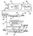
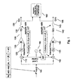
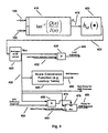
- FIG. 1 is a schematic view of a simplified D-MPSK or MPSK receiver, according to one embodiment.
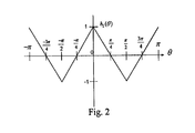
- FIG. 2 is a graph showing one embodiment of the base function, h 2 ( ⁇ ).
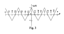
- FIG. 3 is a graph showing another embodiment of the base function, h 4 ( ⁇ ).
- FIG. 4 is a schematic view of a lock detector and SNR estimator that can be used in the receiver of FIG. 1 .
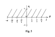
- FIG. 5 is a graph showing values of ⁇ P vs. ⁇ for BPSK, according to one embodiment.
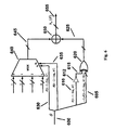
- FIG. 6 is a schematic of one embodiment of a metric generator used to implement one embodiment of the base function, h M ( ⁇ ).
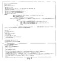
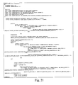
- FIG. 7 is exemplary SystemVerilog code that can be used to synthesize a module (calculate_triangular_LD_metric) for computing one or more embodiments of the base function, h M ( ⁇ ), and an auxiliary module used therein (safely_discard_upper_sign_bits).
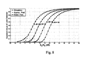
- FIG. 8 is a graph of the expected values of several base functions vs. SNR when the carrier is locked, i.e. h M ( ⁇ ) ⁇ E[h M ( ⁇ n )
- ⁇ , carrier loop is locked] vs. ⁇ , for several M-PSK modulations, according to one or more embodiments. Curves showing simulated (with N 8192), exact (predicted, calculated), and approximate (predicted, calculated) values are shown.
- FIG. 9 is a schematic view of the SNR estimator for D-MPSK or M-PSK that can be used without prior carrier synchronization, according to one embodiment.
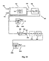
- FIG. 10 is a block diagram illustrating how the same phase determiner can be used to generate phases for use in any one or more of lock detection, SNR estimation, and modulation classification, according to one embodiment.
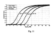
- FIG. 11 is a graph of the expected values of several base functions vs. SNR, i.e. h M D ( ⁇ ) ⁇ E[h M D ( ⁇ , n D )
- E S /N 0 ⁇ ] vs. ⁇ , for several D-MPSK or M-PSK modulations, according to one or more embodiments. Curves showing simulated, exact, and approximate values are shown.
- FIG. 12 is a schematic of a modulation classifier, according to one embodiment.
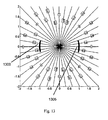
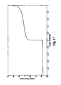
- FIG. 17 is a graph of a lookup table implementation for the calculation of an SNR estimate in dB from the value of q 2,N for a BPSK signal, according to one embodiment.
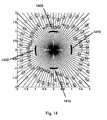
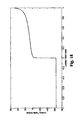
- FIG. 18 is a graph of a lookup table implementation for the calculation of an SNR estimate in dB from the value of q 4,N for a QPSK signal, according to one embodiment.
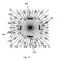
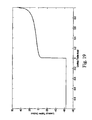
- FIG. 19 is a graph of a lookup table implementation for the calculation of an SNR estimate in dB from the value of q 2,N D for a BPSK signal, according to one embodiment.
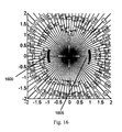
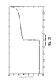
- FIG. 20 is a graph of a lookup table implementation for the calculation of an SNR estimate in dB from the value of q 4,N D for a QPSK signal, according to one embodiment.
- FIG. 21 is exemplary SystemVerilog code that can be used to implement one embodiment of the modulation classifier.
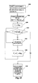
- FIG. 22 is a flowchart showing a method, according to one embodiment, for determining: a lock indicator detection threshold, and a number (N) which determines the number (2N) of symbols to analyze for the generation of each metric.
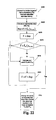
- FIG. 23 is a flowchart showing a method, according to one embodiment, for determining: various thresholds used for modulation classification, and a number (N) which determines the number (2N) of symbols to analyze for the generation of each metric.
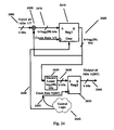
- FIG. 24 is a schematic showing a hardware implementation of an averager in the form of an integrate and dump (IAD) module, according to one embodiment.
- IAD integrate and dump
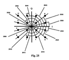
- FIG. 25 is an exemplary rectangular QAM-16 constellation diagram.
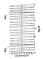
- FIG. 26 is a graph showing one embodiment of the base function, h 12 ( ⁇ ), for rectangular QAM-16.
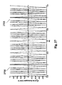
- FIG. 27 is a graph showing one embodiment of the base function, h 12 ( ⁇ ), for rectangular QAM-16.
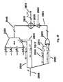
- FIG. 28 is a schematic of one embodiment of the metric generator used to implement one embodiment of the base function, h M ( ⁇ ).
- modulations which are switched in one or more of an adaptive, user, and algorithm controlled manner.
- the modulations are toggled in response to changing channel conditions, communications protocol requirements, or user choice. Switching between the various modulations often has as its core objective the efficient utilization of the available spectrum, in order to achieve high data throughput, while also efficiently utilizing the available transmission and signal processing power at the transmitter and receiver.
- SDR Software Defined Radio
- CR Cognitive Radio
- the receiver's innards can be reconfigured in real-time in order to support different modulations; this is usually achieved through the use of one or both of reconfigurable hardware (such as field programmable gate arrays, hereinafter referred to as FPGAs) and a real-time software component.
- FPGA field programmable gate arrays
- CR the receiver in theory autonomously decides what modulation it sees at its input and applies the appropriate receiver algorithms appropriately.
- CR and SDR go hand in hand; that is a CR will usually have a software defined architecture.
- Modulation classifiers are typically used in CR.
- the CR makes intelligent choices as to the modulation that it sees at its receiver entrance. This is done using the modulation classifier.
- the following embodiments include a new structure for a modulation classifier.
- a lock detector is often subsequently used.
- the following embodiments also include a new structure for a lock detector.
- an SNR estimator is used by the receiver to increase performance of the receiver, as well as to provide a signal quality indication to the receiver operator or for other receivers or entities.
- the following embodiments also include new structures for SNR estimators.
- FIG. 1 A simplified diagram of the front-end of the receiver under discussion is shown in FIG. 1 .
- 1/T is the symbol rate and, as well in the exemplary embodiment, the sample rate.
- a PSK (Phase Shift Keying) modulation scheme is assumed for simplicity.
- M ⁇ 1 ⁇ i.e., the phases are uniformly distributed in the interval [0,2 ⁇ )
- M is called the modulation order or modulation index
- uniformly distributed it is meant that the phase difference between any two symbols of the modulation's constellation diagram is 2 ⁇ k/M, where k is an integer.
- M in general is the number of distinct ideal symbol phases of the symbols in the modulation's constellation. In alternative embodiments other phases are possible for different Ms which are different from those used here in the exemplary embodiment.
- the modulated signal 100 that is present at the output of the receiver's intermediate frequency (IF) downconversion stage is Re[m(t)exp(j ⁇ i t+j ⁇ i )]+n(t), where n(t) is the noise process, with ⁇ i being the received IF carrier frequency in radians/sec, and ⁇ i (in radians) being the phase of the received IF carrier.
- the receiver may not have an intermediate frequency, or may have several intermediate frequencies, in which case appropriate modifications are accordingly made to the exemplary embodiments. Hence, the description of the exemplary embodiments should not be construed as limiting.
- the receiver it is simpler to treat the receiver as a D-MPSK receiver, whether the actual receiver is M-PSK or D-MPSK.
- a D-MPSK signal is identical to an M-PSK signal in terms of the transmitted signal waveform, with the exception that the D-MPSK waveform may be differentially coded whereas sometimes M-PSK signals are not so coded.
- the only difference between M-PSK and D-MPSK is in how these are demodulated (the former, coherently, and the latter, differentially).
- the receiver may be treated as a D-MPSK receiver regardless of whether the actual system is M-PSK or D-MPSK.
- M-PSK Modulation Phase Shift Keying
- O-MPSK Offset MPSK
- D-O-MPSK Differential Offset MPSK
- MSK Minimum Shift Keying
- GMSK Gaussian Minimum Shift Keying
- ⁇ /M-MPSK D- ⁇ /M-MPSK
- FQPSK Feher's QPSK
- SOQPSK Shaped-Offset Quadrature Phase-Shift Keying
- 3 ⁇ /M-8PSK D-3 ⁇ /M-8PSK (Differential 3 ⁇ /M-8PSK
- QAM Quadrature Amplitude Modulation
- OQAM Offset QAM
- PAM-PSK Pulse Amplitude Modulation Phase Shift Keying
- OFDM Orthogonal Frequency Division Multiplexing
- a quadrature receiver front end is assumed for the demodulator of the exemplary embodiment, i.e. multiplication using multipliers 105 , 110 by the local carrier 165 and its quadrature which is generated by passing the local carrier 165 through a 90 degree phase shifter 115 .
- the local oscillator 165 may be controlled or may be free running, depending on the receiver architecture, and, moreover, the receiver structure may be implemented in analog, digital, or mixed signal circuits, or in another suitable manner.
- symbol timing synchronization is assumed, and the Nyquist criterion for zero ISI is assumed obeyed at the outputs of the matched filters 120 , 135 .
- the amplifiers 125 , 140 can be included after the matched filters 120 , 135 .
- the quantity K for the amplifiers 125 , 140 may be a true amplification or it may be a mathematical equivalent (preferably AGC-controlled) I-Q arm gain.
- K is a slow function of time, and is controlled by the AGC in order to attain the desired signal level at the inputs of the I and Q samplers so as to utilize their full dynamic range without saturating.
- the I(t) and Q(t) signals are sampled by samplers 130 , 145 , which operate at a rate of at least 1/T Hertz, from which the relevant samples spaced 1/T seconds apart (corresponding to optimal sampling instances for each symbol) are extracted for the embodiments of the lock detector, SNR estimator, and modulation classifier that are discussed below.
- the sampling rate could be higher than 1/T Hertz.
- the samples that correspond to the baseband symbols are extracted, via one or both of sample selection and interpolation; ideally those samples that correspond to the ideal sampling instances for the received symbols are obtained.
- These ideal sampling instances are usually determined via a symbol sampling synchronization and/or determination circuit that is contained within the receiver.
- the sampling rate may be less than 1/T. In such a case, the structures presented herein would operate upon a subset of the received symbols, which is also possible.
- n I (t) and n Q (t) are used to refer to the noise present before the amplifiers 125 , 140 in the I and Q arms, respectively.
- this noise signal's source is an Additive White Gaussian Noise (AWGN) that is present in the channel, an assumption that is made for the purposes of describing the embodiments described in this disclosure.
- AWGN Additive White Gaussian Noise
- E S ⁇ 1 2 ⁇ ⁇ - ⁇ ⁇ ⁇ ⁇ p ⁇ ( t ) ⁇ 2 ⁇ d t is the symbol energy and N 0 /2 is the AWGN noise power spectral density.
- the phase of the received (complex) baseband symbol r n ⁇ I(n)+j ⁇ Q(n) is ⁇ n ⁇ tan ⁇ 1 (Q(n)/I(n)), which as discussed in more detail below is the instantaneous phase of the received baseband symbol 415 (“received phase”).
- r n
- the received phase ⁇ n 415 is independent of the value of K of the amplifiers 125 , 140 , as can be seen by the fact that K does not appear in (1). Since, as discussed below, the exemplary embodiment relies on operations upon ⁇ n , this means that the embodiment does not depend upon K nor upon the AGC's control of K. This is advantageous, since the AGC is usually non-ideal and the value of K usually does experience fluctuations.
- the only dependence of the embodiment on the AGC is indirect and weak, and will manifest itself if the AGC is so bad that one or both of I(t) 128 and Q(t) 142 are either overdriven or underdriven, which may cause substantial degradations due to one or more of saturation, compression, and quantization noise which are due to the finite dynamic range and quantization accuracy of the samplers 130 , 145 .
- the AGC can easily be made to be sufficiently robust in order to prevent frequent occurrences one or both of overdriving and underdriving, so that the independence of the embodiment from K is a real and substantial advantage in practice.
- I(n) and Q(n) are used to determine the received phase of any one the received baseband symbols, ⁇ n 415 .
- ⁇ n 415 is then input to a base function that outputs a metric from which lock detection and SNR estimation can be performed.
- FIGS. 2 and 3 show two exemplary embodiments of the base function.
- the base function is defined as h M ( ⁇ ) (where M is the modulation order), where ⁇ is an input variable representing an angle in radians.
- the base function includes a curve that is a triangle wave, with periodicity of 2 ⁇ /M radians, with the maxima of the triangles corresponding to the ideal symbol phases or those phases plus any integer multiple of 2 ⁇ .
- h M ( ⁇ ) is defined for all ⁇ ( ⁇ , ⁇ ), but, since any angle (in radians) is angularly equivalent to itself plus any integer multiple of 2 ⁇ (radians), it suffices to implement h M ( ⁇ ) for any interval of length of at least 2 ⁇ .
- the angles upon which h M ( ⁇ ) are implemented span the interval [ ⁇ , ⁇ ) radians.
- the base function from [ ⁇ , ⁇ ) is shown in FIG. 2 ; for QPSK, this is shown in FIG. 3 ; and similarly for other modulations.
- any angle can be expressed as itself plus any integer multiple of 2 ⁇ .
- h M ( ⁇ ) can be implemented for angles residing in any interval of at least length 2 ⁇ (which usually would be a continuous interval (for simplicity) but not necessarily so), with the implementation of h M ( ⁇ ) being accordingly modified.
- h M ( ⁇ ) has a maximum of 1 and a minimum of ⁇ 1.
- h M ( ⁇ ) may have a maximum and minimum with different values, such as A for the maximum and ⁇ A for the minimum, where “A” is some non-zero value.
- the maxima and minima of h M ( ⁇ ) will have identical absolute values (in the exemplary embodiment, for example, the value of this absolute value is “1”).
- h M ( ⁇ ) may have a DC offset, either inevitable (e.g. due to quantization) or intentional, that is for example the maximum will be A+DC and the minimum will be ⁇ A+DC, where “DC” represents the DC offset.
- the ideal symbol phases are located at ⁇ , 0, and ⁇ , one pair of adjacent ideal symbol phases is ⁇ and 0, and another pair of adjacent ideal symbol phases is 0 and ⁇ .
- the ideal symbol phases are located at ⁇ , ⁇ /2, 0, ⁇ /2, and ⁇ , one pair of adjacent ideal symbol phases is ⁇ and ⁇ /2, another pair is ⁇ /2 and 0, another pair is 0 and ⁇ /2, and a fourth pair is ⁇ /2 and ⁇ .
- This exemplary distribution of symbol phases is uniform in that the differences between all of the adjacent ideal symbol phases are identical ( ⁇ /2).
- a non-uniform distribution of phases is possible, in which case the periodicity of the base function ceases to be 2 ⁇ /M.
- I(n) 150 and Q(n) 155 are passed through a phase determiner 410 , which in the depicted embodiment is an inverse tangent function, whose output is the received phase ⁇ n 415 .
- the inverse tangent in all the figures in this disclosure may be implemented for example in one or both of hardware and software, as any one or more of lookup tables, using the CORDIC algorithm, or using another suitable method.
- the received phase ⁇ n 415 is passed through a metric generator 420 , which implements h M ( ⁇ ), such as a logic circuit or a lookup table.
- the output 422 of the metric generator 420 is the metric for that symbol. That metric is averaged, i.e. 2N metrics are averaged to determine an average metric q M,N 430 , that is:
- This averaging can be done such as via an Integrate and Dump (IAD) component 425 as is done in the exemplary embodiment, and the output is denoted q M,N 430 in this exemplary embodiment, and is the average metric.
- IAD Integrate and Dump
- ⁇ , carrier loop is locked] is the expected value of the base function, and for a given SNR
- This calculation can be implemented in a structure such as a lookup table, as is done in the exemplary embodiment, which does not require any real-time mathematical operations, and hence can be implemented in a relatively compact fashion.
- the designer may substitute a suitable default SNR value for this estimate if desired, for example the lowest SNR expected, or alternatively the lowest possible SNR that is expressible using the quantization of the system's datapath. This often makes sense from a design perspective, since such a scenario implies a lack of information about the input signal, and as such, worst-case assumptions are warranted.
- other behaviors for the SNR estimate generation when q M,N ⁇ 0 can be defined.
- the SNR Sufficiency Threshold is 0, since at or below that value the estimate q M,N is considered not sufficient for SNR estimation.
- Other SNR Sufficiency Thresholds are possible for other embodiments.
- the number of samples averaged (2N) may be increased in order to reduce the variance of q M,N 430 in order to arrive at a more accurate value for this quantity.
- an SNR estimate in dB is very useful and is perhaps the standard manner in which SNR is expressed, many other possible SNR indications are possible, for example a logarithmic value in a different base (e.g. ln( h M ⁇ 1 ( ⁇ )) where “ln” is the natural logarithm function).
- the average metric q M,N 430 can itself serve as a proxy for the SNR estimate without further processing, if that value can be used as-is by the receiver as a raw proxy for the SNR estimate and, for example, appropriate arrangements are made in the receiver to handle values of q M,N that do not surpass the SNR sufficiency threshold (for example, simply ignoring them).
- q M,N 430 is compared by a comparison device such as a comparator 455 to an SNR sufficiency threshold 460 (e.g. an SNR sufficiently threshold of 0). If q M,N 430 does not surpass the threshold, then q M,N 430 is considered to be insufficient for SNR estimation and the output 470 of the comparator 455 selects via a data selection device such as a multiplexer 475 a default proxy value for the SNR estimate 465 that is passed through to the output 480 of the multiplexer 475 and serves as a proxy for the SNR estimate that can be used by the receiver.
- a comparison device such as a comparator 455 to an SNR sufficiency threshold 460 (e.g. an SNR sufficiently threshold of 0). If q M,N 430 does not surpass the threshold, then q M,N 430 is considered to be insufficient for SNR estimation and the output 470 of the comparator 455 selects via a data selection device such as a multiplexer 475 a
- the default proxy value for the SNR estimate can be a constant, as in the present embodiment, or in other embodiments it can arrive from another part of the system and may not be constant. If q M,N 430 does surpass the SNR sufficiency threshold 460 , then its value can be used as a proxy for the SNR estimate and it is passed to the output 480 through the multiplexer 475 by virtue of appropriate selection from the output 470 of the comparator 455 .
- a lock detection indicator 445 that signifies that a determination has been made that the local carrier 165 is locked to the received carrier, is obtained by comparing q M,N 430 to a lock indicator detection threshold 432 by use of a comparison device 435 such as a comparator.
- the value that should be chosen as the threshold 432 is dependent upon the value of h M ( ⁇ ), as discussed in more detail below. From h M ( ⁇ ) it may be possible to deduce the optimal thresholds. However, in practice, it is not necessary to calculate the optimal threshold, but rather it can be found via trial and error.
- the thresholds are between 0 and 1 and are set in order to achieve desirable lock and false alarm probabilities, and can be determined experimentally, via theory, via simulations, or via other suitable means.
- more advanced lock indication decisions can be obtained via other methods such as double or triple threshold algorithms.
- Determining values of 10 log 10 ( h M ⁇ 1 ( ⁇ )) may be done, for example, to generate the lookup table values for a lookup table implementation of the Scale Conversion Function 440 .
- Such a method may be used in order to compute the values of a lookup table for the scale conversion function 440 in order to compute 10 log 10 ( h M ⁇ 1 ( ⁇ )) for the case of a positive input to this function; other procedures for obtaining the inverse of a function are also possible in alternative embodiments.
- FIGS. 17 and 18 An example of the values of a lookup table for implementing the scale conversion function 440 in decibels can be found in FIGS. 17 and 18 , for BPSK and QPSK, respectively.
- This lookup table shows the values obtained for an input quantization of 9 bits (1 sign, 8 fraction bits) that represent q M,N 430 , and the output is 12 bits (1 sign bit, 6 whole bits, 5 fractional bits).
- the numerical representation can be chosen by the designer, such as two's complement in the exemplary embodiment. As can be seen in FIGS.
- phase determiner 410 it can be the same one used for determining the symbol phase for subsequently making decisions upon the received symbols (a common task in demodulators). Moreover, the output of this function, the received phase of the baseband symbol ⁇ n 415 , is the same one required regardless of the value of M. Therefore, if structures are implemented for various Ms in the same receiver, such as in a receiver that has support for several modulations, then only one implementation of the phase determiner 410 may be used. This reduces the resources needed and is another advantage of the exemplary embodiment.
- the inverse tangent in the exemplary embodiment is one whose range is [ ⁇ , ⁇ ), that is, it takes into account the quadrant in which r n is present.
- phase determiner 410 behaves similarly to the function a tan 2 in the program MatlabTM.
- the inverse tangent function is used to implement the phase determiner 410
- the phase determiner 410 may be implemented in a different manner, and not necessarily using the inverse tangent function.
- a useful attribute of the lock detector and SNR estimator described above is that in some embodiments an implementation that takes advantage of the linear characteristic of the curves of k M ( ⁇ ) can be used. As discussed below, this implementation can be made to consume relatively few resources. Therefore some embodiments of the lock detectors, SNR estimators, and modulation classifiers in which the ideal symbol phases are uniformly distributed can be implemented using relatively efficient hardware, especially when multiple modulations are needed, since the phase determiner 410 , which in many embodiments is a part that consumes substantial resources, can be reused from the symbol decision circuitry or other circuitry in the receiver that requires such functionality.
- the phase ⁇ is encoded using a suitable encoding such as two's complement encoding which is b bits wide, in the exemplary embodiment from bits b ⁇ 1 (the MSB (Most Significant Bit)) to 0 the LSB (Least Significant Bit).
- the MSB is the sign bit.
- the notation ⁇ [x] refers to significant bit number “x” in the binary representation of ⁇ .
- x is not necessarily the bit with index “x” counting from the right (as is the case in two's complement, starting with bit 0 as the LSB); in general, ⁇ [0] would refer to the LSB, ⁇ [1] would refer to the bit which is with the least significance except for the LSB, ⁇ [2] would refer to the bit that is of the least significance except for ⁇ [1] and ⁇ [0], etc.
- ⁇ [b ⁇ 1] is the sign bit and MSB, and ⁇ [0] is the LSB.
- the notation ⁇ [x:y] is used to denote the binary number formed by the sequence of bits ⁇ [x], ⁇ [x ⁇ 1], ⁇ [x ⁇ 2], .
- the code “10000000” represents the angle ⁇
- the code “10000001” represents the number ⁇ + ⁇ /128, “10000010” represents the angle ⁇ +2 ⁇ /128 and so on
- the code “00000000” represents the angle 0
- the code “00000001” represents the angle ⁇ /128
- the code “00000010” represents the angle 2 ⁇ /128, and so on
- the purpose of this encoding is twofold.
- the position of the LSB (which is the least significant) and MSB (which is the most significant) within the code word, as well as the position of the intermediate bits may depend on the encoding scheme used.
- the concatenation operation is defined as ⁇ x,y> which signifies the concatenation of the binary numbers x and y. For example, ⁇ 0101,1111> is the binary number 01011111.
- the “principal angle” is defined, which is directly proportional to the phase modulo ( ⁇ /2M):
- the proportionality constant is ⁇ /(2M) in the denominator of (5) and the range of the “mod” (modulo) function is [0, ⁇ /(2M)), and these are chosen such that the value of ⁇ P is non-negative and is between 0 and 1, i.e. ⁇ P ⁇ [0,1). That is, the infimum of ⁇ P is 0 and the supremum of ⁇ P is 1.
- the graph of ⁇ P is shown in FIG. 5 .
- Tables 1 and 2 are respectively of h 2 ( ⁇ ) as a function of ⁇ P and h 4 ( ⁇ ) as a function of ⁇ P , according to the present exemplary embodiment.
- FIG. 6 A relatively efficient implementation for computation of h M ( ⁇ ) for an exemplary embodiment is shown in FIG. 6 .
- the bits ⁇ [b-log 2 M ⁇ 1:b-log 2 M ⁇ 2] 630 , 635 are used to control the selection input of data selection hardware such as a multiplexer 640 .
- the output 645 of that multiplexer 640 contains the constant 1, ⁇ 1, or 0 that is added to ⁇ P or ⁇ P in order to form h M ( ⁇ ), as shown in Table 1 and Table 2 above.
- ⁇ P or ⁇ P is generated by doing a controlled inversion using inverting hardware, which in the exemplary embodiment involves XOR-ing (i.e. doing a bitwise exclusive OR) between the bits of ⁇ P , which is composed of bits ⁇ 0, ⁇ [b-3-log 2 M:0]> (concatenation of “0” and ⁇ [b-3-log 2 M:0]) 605 and the NOT 615 (obtained via negating hardware such as a NOT gate 612 ) of the bit e[b-1-log 2 M] 610 .
- XOR-ing i.e. doing a bitwise exclusive OR
- obtaining the negative of a number in two's complement notation i.e. obtaining ⁇ x for a number x
- ( ⁇ x)+1 where “ ⁇ ” represents bitwise inversion.
- the procedure described above may be modified to take this into account in alternative embodiments. Due to the asymmetric nature of two's complement encoding (i.e. that there is one more negative value than there are positive values) in many systems (especially signal-processing structures that are based on averaging, as is done here) ⁇ x is calculated simply as ( ⁇ x) in order to avoid potential overflow problems and in order to simplify logic. This is the procedure adopted for the various exemplary embodiments for two's complement representation.
- this implementation of h M ( ⁇ ) is the one that is used in order to compute h M ( ⁇ n )), where ⁇ n 415 is the input to that function block as used in the exemplary embodiment, as shown in FIG. 4 .
- the angle co, is encoded in the same manner as was previously discussed for ⁇ .
- h M ( ⁇ ) for BPSK, QPSK, 8-PSK and 16-PSK which requires no multiplications or other complicated operations, nor any significantly sized lookup table, is shown in FIG. 7 .
- the input to the function calculate_triangular_LD_metric is the input “theta”, in two's complement notation.
- the values of h M ( ⁇ ) are in the output array All_LD_values[num_modulations-1:0], also in two's complement notation (encoding format is (width bits, from MSB to LSB): 1 sign bit, 1 whole bit, fraction bits).
- the proportionality constant and modulo function range are chosen so that ⁇ P is between 0 and A (i.e. ⁇ P ⁇ [0,A)), where A is the absolute value of the maximum of the base function h M ( ⁇ ) and the base function has no DC offset. That is, the infimum of ⁇ P is 0 and the supremum of ⁇ P is A.
- the normalization in such cases is
- the “principal angle precursor” is defined as ⁇ 0, ⁇ [b-3-log 2 M:0]> for two's complement notation.
- ⁇ P is B multiplied by the Principal Angle Precursor.
- the principal angle precursor and the principle angle are equal, as is the case for the embodiment described in relation to Tables 1 and 2, above.
- “Amplification” in the context of this disclosure does not necessarily mean that the amplitude increases; “amplification” by B in the context of this disclosure could also mean a reduction in amplitude (if B is less than 1) or no change in amplitude (if B equals 1).
- FIG. 28 A relatively efficient implementation for computation of h M ( ⁇ ) for such embodiments is shown in FIG. 28 .
- the bits ⁇ [b-log 2 M-1:b-log 2 M-2] 2830 , 2835 are used to control the selection input of data selection hardware such as a multiplexer 2840 .
- the output of that multiplexer 2845 contains the constant A, ⁇ A, or 0 that is added to ⁇ P or ⁇ P in order to form h M ( ⁇ ), as shown in Table 3 and as discussed above.
- ⁇ P or ⁇ P is generated by first performing a controlled inversion using inverting hardware; in the depicted embodiment, this is done by XOR-ing (i.e. doing a bitwise exclusive OR) between bits ⁇ 0, ⁇ [b-3-log 2 M:0]> (concatenation of “0” and ⁇ [b-3-log 2 M:0]) 2805 and the NOT 2815 (obtained via negating hardware such as a NOT gate 2812 ) of the bit ⁇ [b-1-log 2 M] 2810 (this is done via XOR gates between each of the bits of ⁇ 0, ⁇ [b-3-log 2 M:0]> and the NOT 2815 of the bit ⁇ [b-1-log 2 M] 2810 , which is represented by a single XOR symbol 2820 (but which, it is made clear, reflects the aforementioned bitwise XOR)) and then amplifying the result 2825 of this controlled inversion via an XOR-ing (i.e. doing a bitwise exclusive OR
- the value of h M ( ⁇ ) 2855 is generated by the summation 2850 of the output of the multiplexer 2845 and the output of the output 2829 of the amplification device 2828 using adding hardware such as an adder 2850 .
- This summation complies with all the rules for summation of signals, as appropriate for the chosen representation (for example two's complement in the exemplary embodiment).
- the amplification device 2828 may be omitted, that is, the output of the controlled inversion 2825 can be connected directly to the adding hardware 2850 .
- bits ⁇ [b-3-log 2 M:0] are used, it is possible to use a plurality of the most significant bits of those bits, for example ⁇ [b-3-log 2 M:0] (all the most significant bits of ⁇ [b-3-log 2 M:0], as is done in the exemplary embodiments), or ⁇ [b-3-log 2 M:1] (all the most significant bits of ⁇ [b-3-log 2 M:0] except the LSB), or ⁇ [b-3-log 2 M:2] (all the most significant bits of ⁇ [b-3-log 2 M:0] except the two least significant bits), etc.
- the output 422 of the metric generator 420 is averaged by an averager 425 in order to compute q M,N 430 to obtain an estimate of the expectation E[h M ( ⁇ n )], as noted earlier. In the exemplary embodiment, this is done using the IAD (Integrate and Dump) method.
- IAD Integrate and Dump
- the IAD implementation for fixed-point logic is relatively efficient. In a hardware implementation as shown in FIG. 24 , this is evidenced by the fact that only two registers 2415 , 2435 and one adder 2405 are used, as well as some simple control logic. It is also advantageous in the sense that the bit width of the output 2440 is not larger than the bit width of the input 2400 , that is both are b bits wide.
- the IAD works as follows. The data at the input 2400 is summed via the adder 2405 . This accumulation, over 2N input data values (this is the “Integrate” operation), is updated for each new input data in the accumulation register 2415 .
- the value of the accumulation is stored in the output register 2435 (this is the “Dump” operation).
- the output 2440 is simply the value of the output register 2435 .
- the value of the accumulator register 2415 is cleared via the “Clear” control signal 2450 that is emitted by the Control Logic 2445 .
- This control logic 2445 also controls the clock 2455 of the output register 2435 so that the “Dump” operation occurs at the correct time, i.e. after each batch of 2N samples has been accumulated.
- N is a nonnegative integer power of two, so that log 2 (2N) is a positive integer, so that the number of bits that is discarded is an accurate approximation of the division by 2N.
- the closest nonnegative integer power of 2 that is larger than N, in order to comply with this condition (that 2N be a positive integer power of 2) and also achieve at least the accuracy that would have been achieved with the desired N (if a higher value for N than the desired N is used, this will provide greater accuracy, i.e. will not hurt system performance except via increased latency).
- N the desired N
- N is not a nonnegative integer power of two, and the value of the closest nonnegative integer power of 2 that is larger than N is too large for the desired application, then a different averager structure may be used, or an division by 2N may be inserted in place of block 2425 .
- h M ( ⁇ n ) can be determined from the S-curve function L M ( ⁇ , ⁇ e ) ⁇ E[h M ( ⁇ n )
- ⁇ , ⁇ e , ⁇ 0]. To do this, the function h M ( ⁇ ) is first written as its equivalent Fourier series representation:
- (11) is useful for calculations at high SNR, since in some numerical program such as MatlabTM the calculation of Bessel functions is sometimes not sufficiently accurate at high SNRs.
- FIG. 8 A graph of the expected value of the base function h M ( ⁇ ) ⁇ E[h M ( ⁇ n )
- the “Exact” value is the one in (9), while the “Approximate” value is that of (11).
- ⁇ , carrier loop is unlocked] 0.
- a lock indication 445 is achieved, which indicates that the local carrier is locked to the received carrier.
- the lock indication 445 results.
- the lock detection threshold 432 should be chosen, for example, in order to have the lock detection probability be relatively high compared to the false alarm probability.
- Other combinations of thresholds and N are possible (including different thresholds and values of N for different modulations) and may result in different detection and false alarm probabilities and different latencies. These may be determined for alternative embodiments via any one or more of trial and error, simulation, and calculation and other suitable means.
- the lock indicator detection threshold 432 is denoted as ⁇
- the detection probability that is the probability that the estimator q M,N passes the lock indicator detection threshold ⁇ when indeed the receiver is perfectly locked, is:
- the probability of false alarm that is, the probability that the lock detector will indicate lock when none is present.
- Equations (12) and (13) are nonlinear inequalities. In order to find suitable values for ⁇ and N, (12) and (13) are treated as equalities. This will result in conservative (i.e. somewhat larger than necessary) values of N, which will consequently result in the system's performance in terms of the probability of a false alarm (P FA ) and the probability of detection (P D ) as being more than acceptable.
- N is a constant
- ⁇ M,min could be the minimum SNR in which the receiver is expected to achieve lock for a given M
- N ( erfc - 1 ⁇ ( 2 ⁇ P FA ) - erfc - 1 ⁇ ( 2 ⁇ P D ) h _ M ⁇ ( ⁇ M , m ⁇ ⁇ i ⁇ ⁇ n ) ) 2 ( 17 ) and substitution of (17) into (15) results in:
- FIG. 22 Yet another exemplary method to determine ⁇ and N, which does not use a priori values of P FA and P D , is shown in FIG. 22 .
- the method is as follows. First, the maximum N as allowed by the maximum allowed estimator latency is chosen at block 2200 . In the exemplary embodiment, the estimator latency is dominated by the summing of 2N values as shown in (4), which takes at least 2 ⁇ N ⁇ T seconds. However, in the case that other delays are present, these too are taken into account when calculating the total estimator latency and hence the largest value of N that is allowable in the specific system.
- N is chosen so that the total estimator latency, including the minimal averager delay related to N which is 2 ⁇ N ⁇ T, is such that it does not exceed the maximum latency that is allowable in the particular system.
- the thresholds are preferably in the range (0, h M ( ⁇ M,min ))
- a certain step size is chosen at block 2202 .
- An appropriate step size is such that a sufficient number of values of ⁇ are tested so that the value ultimately chosen is sufficiently (as determined by the designer) close to the optimum in the interval (0, h M ( ⁇ M,min )).
- the step size is 0.1 ⁇ h M ( ⁇ M,min ).
- the detection and false alarm probabilities are then estimated at block 2215 , for example in a laboratory or via computer simulation (e.g. by running a statistically sufficient number of trials and noting when a detection and when a false alarm occur, and thus estimating the false alarm and detection probabilities). These values of the false alarm and detection probabilities are noted.
- ⁇ is increased by the value of Step at block 2220 , and provided that the comparison ⁇ h M ( ⁇ M,min ) performed at block 2210 is false, this process continues so that all the trial values of ⁇ in the interval (0, h M ( ⁇ M,min )) are tested. Then, the value of ⁇ which gives the most acceptable detection and false alarm probabilities is chosen at block 2225 .
- M is defined as the total number of distinct phases in the constellation for the modulation.
- the guiding principle in such an adaptation is that the base function h M ( ⁇ ) has a curve that is triangular in nature, with the maxima of the triangles corresponding to the ideal symbol phases and minima of equal amplitude (assuming no DC offset) but opposite polarity midway between the ideal symbol phases. Retained for convenience is the convention that phases upon which h M ( ⁇ ) operates are defined such that they span the interval [ ⁇ , ⁇ ).
- the phases can be defined as residing in any interval of at least length 2 ⁇ , in which case this entails a corresponding adaptation of the definition of h M ( ⁇ ).
- h M ( ⁇ ) has a maximum of 1 and a minimum of ⁇ 1.
- h M ( ⁇ ) may have a maximum and minimum with different values, such as A for the maximum and ⁇ A for the minimum, where “A” is some non-zero value.
- h M ( ⁇ ) may have a DC offset, either inevitable (e.g. due to quantization) or intentional, that is for example the maximum will be A+DC and the minimum will be ⁇ A+DC, where “DC” represents the DC offset.
- the output of h M ( ⁇ ) may span any suitable interval, such as any suitable subset of ( ⁇ , ⁇ ), when implemented for example using software.
- the graph of the function h 12 ( ⁇ ) for Rectangular QAM-16 is shown in FIG. 26 .
- the domain of h 12 ( ⁇ ) is [ ⁇ , ⁇ ), between the two dashed lines 2600 , 2605 .
- the “o” markers represent ideal symbol phases and the “x” markers are the points midway between the ideal symbol phases.
- h 12 ( ⁇ ) is defined by the linking of h 12 ( ⁇ ) in the interval [ ⁇ , ⁇ ) to its periodic extensions, i.e.
- references to the average metric q M,N 430 “surpassing” a “threshold” refers to q M,N 430 being greater than the threshold in embodiments in which the base function used to generate q M,N 430 is such that the ideal symbol phases correspond to the maxima of the base function (as in the exemplary embodiments), and refers to q M,N 430 being less than the threshold in embodiments in which the base function used to generate q M,N 430 is such that the ideal symbol phases correspond to the minima of the base function.
- the thresholds will in general be the negative of the thresholds of the corresponding exemplary embodiments, and the expectation of the base function will be in general the negative of the expectation of the base function of the corresponding exemplary embodiments.
- q M,N 430 “surpassing” the lock indicator detection threshold 432 may refer to q M,N 430 being ⁇ 0.5 when the lock indicator detection threshold 432 is ⁇ 0.1.
- h M D ( ⁇ ) ⁇ h M ( ⁇ ) for the definitions used in exemplary embodiments above for uniformly distributed phases, and hence the base function h M D ( ⁇ ) can utilize the same relatively efficient implementations that are possible for h M ( ⁇ ) for uniformly distributed phases, as described above.
- the input to h M ( ⁇ ) is the phase of the received baseband symbol itself
- h M ( ⁇ ) When the symbol phases are not uniformly distributed, such as in other embodiments, as noted earlier h M ( ⁇ ) will be such that with the maxima of the triangles correspond to the ideal symbol phases, whatever they may be. Analogously, when the ideal symbol phases are not uniformly distributed, h M D ( ⁇ ) will be the triangle wave function with maxima corresponding to the ideal phase differences, which are defined as the set of all possible phase differences between ideal constellation symbols. As was the case for h M ( ⁇ ), h M D ( ⁇ ) is defined for all ⁇ ( ⁇ , ⁇ ), but, since any angle (in radians) is angularly equivalent to itself plus any integer multiple of 2 ⁇ (radians), it suffices to implement h M D ( ⁇ ) for any interval of length of at least 2 ⁇ .
- the domain of angles upon which h M D ( ⁇ ) is implemented span the interval [ ⁇ , ⁇ ) radians.
- ⁇ 1 3 ⁇ /4
- ⁇ 2 5 ⁇ /4
- ⁇ 3 7 ⁇ /4
- h M D ( ⁇ ) will have its maxima located at the ideal phase differences or their equivalent angles as expressed in the range [ ⁇ , ⁇ ), which are for this example at angles ⁇ , ⁇ /2,0, ⁇ /2 ⁇ .
- the adjacent ideal phase differences are ⁇ and ⁇ /2,
- the phase differences upon which h M D ( ⁇ ) operates are defined such that they span the interval [ ⁇ , ⁇ ).
- the phase differences can be defined as residing in any appropriate interval of length of at least 2 ⁇ , in which case this entails a corresponding adaptation of the implementation of h M D ( ⁇ ).
- h M D ( ⁇ ) has a maximum of 1 and a minimum of ⁇ 1.
- h M D ( ⁇ ) may have a maximum and minimum with different values, such as A for the maximum and ⁇ A for the minimum, where “A” is some non-zero value.
- h M D ( ⁇ ) may have a DC offset, either inevitable (e.g. due to quantization) or intentional, that is for example the maximum will be A+DC and the minimum will be ⁇ A+DC, where “DC” represents the DC offset.
- excessive DC offsets may cause performance degradations.
- FIG. 9 A possible implementation of the appropriate hardware structure is shown in FIG. 9 , which shall now be discussed.
- v n ⁇ r n ⁇ r n - 1 * ⁇ r n ⁇ ⁇ ⁇ r n - 1 ⁇ ⁇ is defined as the normalized pseudo-coherently demodulated M-PSK signal. Defined now is ⁇ n D ⁇ ( ⁇ n ⁇ n-1 )mod 2 ⁇ , where the range of the modulo operation is [ ⁇ , ⁇ ) such that ⁇ n D ⁇ [ ⁇ , ⁇ ).
- the function 10 log 10 (( h M D ) ⁇ 1 ( ⁇ )) can be implemented in a structure such as lookup table, as is done in the exemplary embodiment, following for example a similar procedure for finding the inverse of a function as was detailed for finding 10 log 10 (( h M ) ⁇ 1 ( ⁇ ), as discussed above.
- the received phase ⁇ n 415 is obtained via a phase determiner such as a 4-quadrant inverse tangent function 410 from the I(n) 150 and Q(n) 155 samples.
- the received phase difference 915 between this symbol's received phase ⁇ n 415 and the previous symbol's received phase ⁇ n-1 905 is obtained by means of a subtracting device, such as a subtractor 910 , in the exemplary embodiment.
- phase difference determiner may determine the phase difference between any pair of symbols used to modulate the received carrier.
- one of the symbols of the pair immediately follows the other of the symbols of the pair; i.e., one of the symbols is transmitted immediately after the other.
- the metric generator 920 may be used to evaluate the base function at phase differences determined from pairs of symbols in which one symbol is not the symbol immediately preceding the other but rather any other symbol. That is, it is possible to define in alternative embodiments ⁇ n D ⁇ ( ⁇ n ⁇ n-k )mod 2 ⁇ where k is some nonzero integer which may or may not be constant.
- the implementation is substantially the same except that the delay element 900 corresponds to the delay between those symbols, namely it would be a delay z ⁇ k , which could be implemented for example as a concatenation of k registers clocked by a clock of frequency 1/T. For causal systems such a k would be positive although non-causal systems do not have such a restriction.
- This averaging is done by an averager 930 that can be implemented for example using an Integrate and Dump (IAD) module, as shown in FIG. 24 for the exemplary embodiment and which was discussed above.
- the output of the averager 930 which for a given SNR ⁇ is an approximation of the expected value of the base function h M D ( ⁇ ) ⁇ E[h M D ( ⁇ , n D )
- E S /N 0 ⁇ ], is denoted q M,N D 935 .
- the modulo operation is done automatically by virtue of the subtraction performed by the subtractor 910 .
- the chosen encoding scheme as might be the case in other embodiments, is such that a modulo operation is not encompassed by the subtraction operation, then an explicit modulo operation which restricts the range of ⁇ n D to [ ⁇ , ⁇ ) is inserted between the subtractor 910 and the metric generator 920 . This is the modulo 2 ⁇ operator 918 .
- Such a modulo operation may be implemented by structures such as a lookup table or by other suitable means. If the numerical notation is such that the modulo operation is done automatically by virtue of the subtractor 910 , as is the case in the exemplary embodiment, then the modulo 2 ⁇ operator 918 can be bypassed or omitted and the output of the subtractor 910 can be connected directly to the input of the metric generator 920 . In some encodings, such as one's complement encoding, the subtraction operation approximates, but does not exactly implement, the modulo 2 ⁇ operation. In such an embodiment, the designer may choose to omit the modulo 2 ⁇ operation because the inaccuracy incurred by such an omission may be deemed to be acceptable.
- FIG. 19 and FIG. 20 An example of the values of a lookup table for determining the SNR estimate 945 in decibels can be found in FIG. 19 and FIG. 20 , for BPSK and QPSK, respectively.
- These Figures show the values obtained for an input quantization of 9 bits (1 sign, 8 fraction bits) that represent q M,N D 935 , and from an output of 12 bits (1 sign bit, 6 whole bits, 5 fractional bits).
- the numerical representation can be chosen by the designer, such as two's complement in the exemplary embodiment. As can be seen in FIGS.
- the SNR Sufficiency Threshold is 0, since at or below that value the estimate q M,N D 935 is considered not sufficient for SNR estimation.
- Other SNR Sufficiency Thresholds are possible for other embodiments.
- an SNR estimate in dB is very useful and is perhaps the standard manner in which SNR is expressed, many other possible SNR indications are possible, for example decibels in a different base (e.g. ln( h M D ) ⁇ 1 (q M,N D )) where “ln” is the natural logarithm function).
- the average metric q M,N D 935 can itself serve as a proxy for the SNR estimate with no further processing necessary, if that value can be used as-is by the receiver as a raw proxy for the SNR estimate and, for example, appropriate arrangements are made in the receiver to handle values of q M,N D that do not surpass the SNR sufficiency threshold (for example, simply ignoring them).
- q M,N D 935 is compared via a comparison device such as a comparator 950 to an SNR sufficiency threshold 955 (e.g. an SNR sufficiently threshold of 0). If q M,N D 935 does not surpass the threshold, then q M,N D 935 is considered to be insufficient for SNR estimation and the output 958 of the comparator 950 selects via a data selection device such as a multiplexer 960 a default proxy value for the SNR estimate 965 . This selected value is passed through to the output 970 of the multiplexer 960 and serves as a proxy for the SNR estimate that can be used by the receiver.
- a comparison device such as a comparator 950 to an SNR sufficiency threshold 955 (e.g. an SNR sufficiently threshold of 0). If q M,N D 935 does not surpass the threshold, then q M,N D 935 is considered to be insufficient for SNR estimation and the output 958 of the comparator 950 selects via a data selection device such as
- the default proxy value for the SNR estimate can be a constant, or in other embodiments it can arrive from another part of the system and may not be constant. If q M,N D 935 does surpass the SNR sufficiency threshold, then it can be used as a proxy for the SNR estimate and it is passed to the to the output 970 through the multiplexer 960 by virtue of appropriate selection from the output 958 of the comparator 950 .
- h M D ( ⁇ ) can be calculated, and such a calculation is now presented for the exemplary embodiment.
- the “Exact” (predicted) value is the one in (25), while the “Approximate” (predicted) value is that of (27). Values obtained via simulation are also shown.
- FIG. 10 shows how the received phase ⁇ n 415 is used to generate both q M,N D D 935 b and q M,N C 430 b regardless of the value of M or N.
- phase determiner 410 can be utilized, regardless of the number of modulations supported and regardless of the number of structures that compute q M,N D D 935 b and q M,N C 430 b . This reduces the resources needed and is an advantage of the exemplary embodiment.
- h M D ( ⁇ ) has a curve that is triangular in nature, with maxima of the triangles corresponding to the ideal phase differences of the symbols, which are in turn defined as the set of possible differences between ideal symbol phases.
- the function h M D ( ⁇ ) will have minima of equal amplitude but opposite polarity located midway between its maxima. Retained for convenience is the convention that angles upon which h M D ( ⁇ ) operates are defined such that they span the interval [ ⁇ , ⁇ ).
- the angles can be defined as residing in any appropriate interval of length of at least 2 ⁇ , in which case this entails a corresponding adaptation of the definition of h M D ( ⁇ ).
- h M D ( ⁇ ) has a maximum of 1 and a minimum of ⁇ 1.
- h M D ( ⁇ ) may have a maximum and minimum with different values, such as A for the maximum and ⁇ A for the minimum, where “A” is some non-zero value.
- h M D ( ⁇ ) may have a DC offset, either inevitable (e.g. due to quantization) or intentional, that is for example the maximum will be A+DC and the minimum will be ⁇ A+DC, where “DC” represents the DC offset.
- the output of h M ( ⁇ ) may span any suitable interval, such as any suitable subset of ( ⁇ , ⁇ ), when implemented for example using software.
- FIG. 25 the Rectangular QAM-16 constellation is shown. Angles of the ideal symbol phases are denoted by the corresponding arcs.
- the graph of the function h 12 D ( ⁇ ) for Rectangular QAM-16 is shown in FIG. 27 .
- the domain of the implementation of h 12 D ( ⁇ ) for the exemplary embodiment is [ ⁇ , ⁇ ), between the two dashed lines 2700 , 2705 .
- the “o” markers represent the ideal phase differences, which are the phase differences between ideal symbol phases and the “x” markers are the points midway between the ideal phase differences.
- the structures described for SNR estimation and modulation classification that rely upon h M D ( ⁇ ) will also work for cases other than those discussed in the exemplary embodiments.
- the expectations which govern the various calculations e.g. the definition of the expected value of the base function h M D ( ⁇ ) ⁇ E[h M D ( ⁇ , n D )
- the specific base function h M D ( ⁇ ) that should be used by a designer is defined not only by M, but also by the specific modulation used, and as already noted this also is taken into account when, for example, implementing the function in hardware or calculating the expected value of the base function h M D ( ⁇ ) ⁇ E[h M D ( ⁇ , n D )
- E S /N 0 ⁇ ].
- references to the average metric q M,N D 935 “surpassing” a “threshold” refers to q M,N D being greater than the threshold in embodiments in which the base function used to generate q M,N D is such that the ideal phase differences correspond to the maxima of the base function (as is the case in the exemplary embodiments), and refers to q M,N D being less than the threshold in embodiments in which the base function used to generate q M,N D is such that the ideal phase differences correspond to the minima of the base function.
- the thresholds will in general be the negative of the thresholds of the corresponding exemplary embodiments, and the expectation of the base function will be in general the negative of the expectation of the base function of the corresponding exemplary embodiments.
- q M,N D “surpassing” the SNR sufficiency threshold 955 may refer to q M,N D being ⁇ 0.5 when the SNR sufficiency threshold 955 is ⁇ 0.1.
- the values of q M,N D 935 can be used for modulation classification, as shown in FIG. 12 .
- the operation of the metric generator 920 is considered when the input signal has the “wrong” M; i.e., a value for M that does not correspond to the value of M for which the metric generator 920 is designed.
- the input signal modulation index is M T (with “T” standing for “True”).
- the constellation consisting of the M T possible constellation points is a symmetric subset of the M W constellation points for which the estimator q M W ,N D is designed. Accordingly, since the metric generator 920 is NDA, then the metric generator 920 will behave the same as if the correct constellation were input to it.
- ⁇ n exp(j ⁇ n D ), where
- ⁇ n is the pseudo coherently demodulated normalized constellation of the input signal.
- ⁇ n is the pseudo coherently demodulated normalized constellation with modulation index M T .
- q 4,N D for the symbols shown in FIG. 14 is the sum of the contours upon which those symbols land for each symbol, divided by the number of symbols. Due to the symmetry of the contours and the equiprobability of the symbols, the contribution of each of the arcs 1400 , 1405 , 1410 , 1415 is equal.
- FIGS. 13 and 15 To exemplify this, refer to FIGS. 13 and 15 .
- FIG. 15 results.
- M ⁇ C max M i ⁇ ⁇ q M i , N i D
- i 1 , 2 , ... ⁇ , L ⁇ ( 29 )
- ⁇ circumflex over (M) ⁇ C is used to denote the decided upon modulation index, which nominally equals M C .
- the correct modulation classification is the modulation that corresponds to the lowest index j for which q M j ,N j D is bigger than some corresponding validity threshold ⁇ j (heuristically, the validity threshold should be chosen so that for the lowest SNR for which reliable modulation classification is desired for the modulation with index j, there is a high probability that q M j ,N j D will be larger than that validity threshold, as shall be discussed below).
- the decision rule of (30) is given for an exemplary case where there are 4 possible modulations to detect, with indices M 1 , M 2 , M 3 , and M 4 .
- Other embodiments may handle more than four modulations, or less than four modulations.
- the modulation decision method of (30) is implemented as shown in FIG. 12 .
- the structure will output the detection decision 1275 as 0 for BPSK, 1 for QPSK, 2 for 8-PSK, and 3 for 16-PSK.
- the comparators 1230 , 1232 , 1234 , 1236 are used to compare each of the average metrics 1200 , 1205 , 1210 , 1215 to their respective validity thresholds 1226 , 1224 , 1222 , 1220 .
- Each of the comparators 1230 , 1232 , 1234 , 1236 is communicatively coupled to its own averager 930 (not shown in FIG.
- each of the comparators 1230 , 1232 , 1234 , 1236 except the comparator 1236 that receives as input the average metric 1215 associated with the highest value of M are coupled to data selectors such as multiplexers 1240 , 1242 , 1244 .
- Each of the comparators 1230 , 1232 , 1234 is coupled to the selection input of one of the multiplexers 1240 , 1242 , 1244 and the multiplexers 1240 , 1242 , 1244 are communicatively coupled together in series (“daisy chained”) such that the data output (the “modulation decision” 1275 ) of the last of the multiplexers in the series is a particular one of the data inputs of the multiplexers 1240 , 1242 , 1244 .
- the modulation decision 1275 is 0 if the correct modulation is M 1 ; 1 if the correct modulation is M 2 ; 2 if the correct modulation is M 3 ; and 3 if the correct modulation is M 4 .
- M 1 and M 2 are adjacent powers of two; M 2 and M 3 are adjacent powers of two; and M 3 and M 4 are adjacent powers of two.
- Such a set of values of M is beneficial because the fact that such a relationship between the values of M is present is part of the reason that the metric generators behave as they do when applied to “wrong” modulations.
- Such a “decision valid” indication 1270 is generated from the values of the average metrics q M i ,N i D 1200 , 1205 , 1210 , 1215 and the validity thresholds 1220 , 1222 , 1224 , 1226 , via passing the outputs 1250 , 1252 , 1254 , 1256 of the comparators 1230 , 1232 , 1234 , 1236 through ORing logic such as in the form of a simple “OR” function 1260 as seen in FIG. 12 .
- FIG. 12 are a schematic representation which nominally represents a hardware implementation for the exemplary embodiment, though in other embodiments the structure may be implemented for example in software or in a combination of software or hardware or via other means, and so the implementation presented here is not limiting.
- FIG. 21 Another possible embodiment of the modulation decision logic is given in FIG. 21 as SystemVerilog code.
- the input clk is the clock by which the average metrics q M i ,N i D 1200 , 1205 , 1210 , 1215 are received.
- the input estimator_input contains a concatenated two's-complement version of all the average metrics q M i ,n i D 1200 , 1205 , 1210 , 1215 , each of which has a bus width in bits as specified in the parameter width, for the various modulations for which detection is desired.
- the input yes_signal_threshold contains the validity thresholds for the various modulations for which detection is desired, expressed as a concatenated two's-complement encoding of the validity thresholds 1220 , 1222 , 1224 , 1226 , each of which has a bus width in bits as specified in the parameter width.
- M i 2, 4, 8, 16, and a different number of modulations can be handled by changing the parameter numestimators.
- the output modulation_decision will output “0” for BPSK, “1” for QPSK, “2” for 8-PSK, and “3” for 16-PSK, as was the case in the circuit of FIG. 12 .
- the output classification_valid is “1” if the output modulation_decision is a true best guess of the modulation (i.e. if at least one of the values of q M i ,N i D has crossed the validity threshold) or “0” if none of the average metrics q M i ,n i D has crossed the validity threshold.
- the validity thresholds ⁇ i are between 0 and 1, and may be adjusted, through any one or more of experimentally, theoretical calculations, or simulation, in order to achieve the desired performance.
- Another parameter that may be adjusted is N i , in order to determine the balance between the estimation latency and lower variance.
- N i is a parameter that may be adjusted.
- a larger N i will facilitate better estimator accuracy (i.e. less variance of q M i ,N i D ) but implies a higher latency.
- a balance can be struck, which is dependent on each individual system and application, in order to choose sufficiently large N i so that the estimators are sufficiently accurate without introducing excessive latency.
- the validity thresholds and the values of N i are defined and the probability that each of the average metrics q M i ,N I D will cross that validity threshold are ascertained. These can be done using any one or more of a heuristic manner, by trial and error, and via calculation. A calculation method is now presented, although it is not necessary to actually engage in such calculation as the validity thresholds can be found via trial and error quite rapidly, as discussed in further detail below.
- the validity threshold for modulation index i be ⁇ i
- the probability that the average metric q M i ,N i D passes the validity threshold is:
- N i 2 ⁇ ( erfc - 1 ⁇ ( 2 ⁇ P FA , i ) - erfc - 1 ⁇ ( 2 ⁇ P D , i ) h _ M i D ⁇ ( ⁇ M i , m ⁇ ⁇ i ⁇ ⁇ n D ) ) 2 ( 36 ) and substitution of (36) into (34) results in:
- ⁇ i erfc - 1 ⁇ ( 2 ⁇ P FA , i ) ⁇ h _ M i D ⁇ ( ⁇ M i , m ⁇ ⁇ i ⁇ ⁇ n D ) erfc - 1 ⁇ ( 2 ⁇ P FA , i ) - erfc - 1 ⁇ ( 2 ⁇ P D , i ) ( 37 )
- FIG. 23 Yet another method to determine ⁇ i and N i , which does not require a priori specification of P D,i and P FA,i , is shown in FIG. 23 .
- the method is as follows. First, the maximum N i as allowed by the maximum allowed estimator latency is chosen at block 2300 . In the exemplary embodiment, the estimator latency is usually dominated by the sum of 2N i values as seen in (21), which takes at least 2 ⁇ N i ⁇ T seconds. However, in the case that other delays are present, these too are taken into account when calculating the total estimator latency and hence the largest value of N i that is allowable in the specific system.
- N i is chosen so that the total estimator latency, including the minimum averager delay attributable to N i which is 2 ⁇ N i ⁇ T, is such that it does not exceed the maximum delay that is allowable in the particular system. Since the validity thresholds are typically in the range (0, h M i D ( ⁇ M i ,min D )), and since it is desired that the algorithm complete in a finite number of stages, then a certain step size is chosen at block 2302 . An appropriate step size is such that a sufficient number of values of ⁇ i are tested so that the value ultimately chosen is sufficiently (as determined by the designer) close to the optimum in the interval (0, h M i D ( ⁇ M i,min D )).
- the step size is 0.1 ⁇ h M D ( ⁇ M i ,min D ).
- the detection and false alarm probabilities are then estimated at block 2315 , for example using one or more of a laboratory or computer simulations (e.g. by running a statistically sufficient number trials and noting when a detection and when a false alarm occurred, and thus estimating the false alarm and detection probabilities). These values of the false alarm and detection probabilities are noted.
- ⁇ i is increased by the value of Step at block 2320 , and provided that the comparison ⁇ i ⁇ h M i D ( ⁇ M i ,min D ) performed at block 2310 is false, this process continues so that all the trial values of ⁇ i in the interval (0, h M i D ( ⁇ M i ,min D )) are tested. Then, the value of ⁇ i which give the most acceptable detection and false alarm probabilities is chosen at block 2325 .
- references to the average metric q M i ,N i D ( 1200 , 1205 , 1210 , 1215 ) “surpassing” a “threshold” refers to q M i ,N i D being greater than the threshold in embodiments in which the base function used to generate q M i ,N i D is such that the ideal phase differences correspond to the maxima of the base function (as is the case in the exemplary embodiments), and refers to q M i ,N i D being less than the threshold in embodiments in which the base function used to generate q M i ,N i D is such that the ideal phase differences correspond to the minima of the base function.
- the thresholds will in general be the negative of the thresholds of the corresponding exemplary embodiments, and the expectation of the base function will be in general the negative of the expectation of the base function of the corresponding exemplary embodiments. Appropriate changes are then accordingly made to various parts of such embodiments.
- q M i ,N i D ( 1200 , 1205 , 1210 , 1215 ) “surpassing” the associated validity threshold ( 1220 , 1222 , 1224 , 1226 ) may refer to q M i ,N i D being ⁇ 0.5 when the associated validity threshold is ⁇ 0.1.
- the FPGA was also used to implement, as a point of comparison, the structures described in LINN, Y. & PELEG, N. 2004.
- several documents that calculate the equivalent gate count for FPGA structures were used as sources. These are documents Altera Inc.
- the total number of required gates has decreased substantially, by about 66.06%, i.e. only about a third of the logic resources are required as compared to the prior art (201908 equivalent gates as opposed to 594964 for the prior art). This also allows for a similar and corresponding reduction in power consumption and circuit area for the embodiment as compared to the prior art.
- the total number of required gates has decreased substantially, by about 95.79% (202058 equivalent gates vs. 4802568 equivalent gates for prior art), i.e. only about 4% of the logic resources are required as compared to prior art. This represents about a 25-fold reduction in logic, or an increased efficiency of 2500%. This also allows for a similar and corresponding reduction in power consumption and circuit area for the embodiment as compared to the prior art.
- the advantage of the present structures increases as the number of supported modulations increases, i.e. the advantage would be even greater if 5 or 6 modulations (e.g. also 32-PSK and 64-PSK) were implemented as well.
- the above comparisons do not include the modulation classification embodiments discussed above.
- the implementation of the structure in FIG. 12 occupied 28 logic cells and 6 registers in the Altera FPGA used for implementation, i.e. about 325 additional equivalent gates. This is a relatively small amount of logic, i.e. the modulation classifiers utilize relatively little additional logic. This is orders of magnitude more efficient than the prior art.
- those embodiments that utilize the principal angle to evaluate the base function may be implemented using a relatively simple arrangement of logic gates, multiplexers, and adders, and that can make them quite useful in one or both of CR and SDR.
- Many modulation classification algorithms, while mathematically viable, are too cumbersome and resource hungry for practical use.
- the modulation classifiers discussed above do not require divisions, multiplications, Fourier transforms, or other complicated transforms.
- no carrier synchronization of the input signal is needed to perform SNR estimation or modulation classification. This can be beneficial, since avoiding the need to recover the carrier phase avoids the inherent delay, risk of failure, and complexity of this synchronization operation (which is usually implemented as a phase locked loop (PLL) or other synchronization circuitry).
- PLL phase locked loop
- NDA Non-Data Aided
- DA Data Aided
- DA methods require prior knowledge of some or all of the transmitted data sequence upon which the modulation classification estimation is done. This is problematic on several levels: for example, often some of the data throughput is sacrificed in DA methods in order to send known symbols, such as pilot symbols, and the receiver must known when those known data symbols are present, implying some sort of required prior frame synchronization. NDA methods, such as those presented above, avoid these pitfalls.
- the foregoing embodiments operate using only 1 sample/symbol.
- the computational complexity and power usage of the foregoing embodiments are accordingly reduced as compared to structures that require a higher sampling rate.
- the performance of the foregoing embodiments are largely independent of the AGC (Automatic Gain Control).
- the various thresholds and functions used in the embodiments of the modulation classifier or lock detector are largely independent of the AGC's performance or operating point, and their overall performance is also resilient to AGC imperfections. This is in sharp contrast to many typical modulation classifiers, SNR estimators, and lock detectors, which depend in some way on the AGC's operating point and performance, particularly with respect to calibration of the classification and lock thresholds.
- the AGC loops generally converge very slowly compared to the symbol rate, and this implies that a modulation classification scheme that requires a priori knowledge of the AGC operating point must wait for the AGC loop to converge, hence prolonging the time until an accurate classification can be made.
- This problem is not present in the foregoing embodiments that are largely independent of the AGC.
- modulation classifiers' hardware structure can be used concurrently, as parts of the carrier lock detector and SNR estimator, hence simplifying the overall structure of the receiver.
- the foregoing embodiments may be encoded on to a computer readable medium that is readable by a processor so as to configure the receiver to have the functionality described above.
- the computer readable medium may be flash memory, RAM, any other suitable disc or semiconductor based memory, or any other suitable computer readable medium.
- Using software to implement the foregoing embodiments may be suitable when an embodiment of the base function is used that does not lend itself to a relatively efficient hardware implementation, or when the power consumption advantages of hardware are immaterial, for example.
- the example embodiments above are described as various interconnected functional blocks, which may be implemented using one or both of distinct hardware and software modules. This is not necessary, however, and there may be cases where these functional blocks or modules are equivalently aggregated into a single logic device, program or operation with unclear boundaries.
- the functional blocks, software, and hardware modules can be implemented by themselves, or in combination with other operations in one or both of hardware and software, or via any other suitable implementation method.
Landscapes
- Engineering & Computer Science (AREA)
- Computer Networks & Wireless Communication (AREA)
- Signal Processing (AREA)
- Physics & Mathematics (AREA)
- Electromagnetism (AREA)
- Power Engineering (AREA)
- Quality & Reliability (AREA)
- Digital Transmission Methods That Use Modulated Carrier Waves (AREA)
- Error Detection And Correction (AREA)
Abstract
Description
is the symbol energy and N0/2 is the AWGN noise power spectral density. The phase of the received (complex) baseband symbol rn≡I(n)+j·Q(n) is φn≡tan−1 (Q(n)/I(n)), which as discussed in more detail below is the instantaneous phase of the received baseband symbol 415 (“received phase”). In polar coordinates, rn=|rn|exp(jφn).
Δφn≡φn−(−ΔωnT+θ e) (2)
where −π≦Δφ≦π.
Lock Detector and SNR Estimator
and when the carrier loop is in lock,
and in an ergodic system (as is commonly assumed for physical systems)
It should be noted that in other embodiments other averaging definitions can be used than that of (4), for example the number of samples averaged does not need to be even, nor do the samples need to be defined as between −N+1 and N, nor do the set of symbol intervals upon which the average is calculated need to be adjacently successive in time.
| TABLE 1 |
| Value of h2 (θ) as a function of θP |
| Angular | Value of | Ad- | ||||
| Interval for | h2 (θ) as a | θP | dition | |||
| input | function | Multi- | to θP or | |||
| variable θ | of θP | plier | −θP | θ[b − 1] | θ[b − 2] | θ[b − 3] |
| [−π, −3π/4) | 1 − θP | −1 | 1 | 1 | 0 | 0 |
| [−3π/4, −π/2) | −θP | −1 | 0 | 1 | 0 | 1 |
| [−π/2, −π/4) | −1 + |
1 | −1 | 1 | 1 | 0 |
| [−π/4, 0) | |
1 | 0 | 1 | 1 | 1 |
| [0, π/4) | 1 − θP | −1 | 1 | 0 | 0 | 0 |
| [π/4, π/2) | −θP | −1 | 0 | 0 | 0 | 1 |
| [π/2, 3π/4) | −1 + |
1 | −1 | 0 | 1 | 0 |
| [3π/4, π) | |
1 | 0 | 0 | 1 | 1 |
| TABLE 2 |
| Value of h4 (θ) as a function of θP |
| Value of | Addition | ||||||
| Angular | h4 (θ) as a | θP | to θP | ||||
| Interval | function of θP | Multiplier | or −θP | θ[b − 1] | θ[b − 2] | θ[b − 3] | θ[b − 4] |
| [−π, −7π/8) | 1 − θP | −1 | 1 | 1 | 0 | 0 | 0 |
| [−7π/8, −3π/4) | −θP | −1 | 0 | 1 | 0 | 0 | 1 |
| [−3π/4, −5π/8) | −1 + θP | 1 | −1 | 1 | 0 | 1 | 0 |
| [−5π/8, −π/2) | θP | 1 | 0 | 1 | 0 | 1 | 1 |
| [−π/2, −3π/8) | 1 − θP | −1 | 1 | 1 | 1 | 0 | 0 |
| [−3π/8, −π/4) | −θP | −1 | 0 | 1 | 1 | 0 | 1 |
| [−π/4, π/8) | −1 + θP | 1 | −1 | 1 | 1 | 1 | 0 |
| [π/8, 0) | θP | 1 | 0 | 1 | 1 | 1 | 1 |
| [0, π/8) | 1 − θP | −1 | 1 | 0 | 0 | 0 | 0 |
| [π/8, π/4) | −θP | −1 | 0 | 0 | 0 | 0 | 1 |
| [π/4, 3π/8) | −1 + θP | 1 | −1 | 0 | 0 | 1 | 0 |
| [3π/8, π/2) | θP | 1 | 0 | 0 | 0 | 1 | 1 |
| [π/2, 5π/8) | 1 − θP | −1 | 1 | 0 | 1 | 0 | 0 |
| [5π/8, 3π/4) | −θP | −1 | 0 | 0 | 1 | 0 | 1 |
| [3π/4, 7π/8) | −1 + θP | 1 | −1 | 0 | 1 | 1 | 0 |
| [7π/8, π) | θP | 1 | 0 | 0 | 1 | 1 | 1 |
-
- 1. θP is the signed binary two's complement number <0,θ[b-3-log2 M:0]> (concatenation of “0” and θ[b-3-log2 M:0]), where it is understood that in the numerical encoding convention chosen by the designer the range of θP is [0,1) (or as close to that range as can be expressed by the resolution of the quantization of θP).
- 2. θP is either inverted or not, according to the bit θ[b-1-log2 M], for example as seen in Table 1 and Table 2.
- 3. Either 1 or −1 or 0 (or as close to those values as can be expressed by the resolution of the quantization) is added to θP or its inverse, as determined in
step 2, according to bits θ[b-log2 M−1:b-log2 M−2], for example as seen in Table 1 and Table 2.
For example, for BPSK:
| TABLE 3 |
| Value of h2 (θ) as a function of θP for alternative embodiment where the |
| maximum value of h2 (θ) is A |
| Angular | Value of | Ad- | ||||
| Interval for | h2 (θ) as a | θP | dition | |||
| input | function | Multi- | to θP or | |||
| variable θ | of θP | plier | −θP | θ[b − 1] | θ[b − 2] | θ[b − 3] |
| [−π, −3π/4) | A − θP | −1 | |
1 | 0 | 0 |
| [−3π/4, −π/2) | −θP | −1 | 0 | 1 | 0 | 1 |
| [−π/2, −π/4) | −A + |
1 | −A | 1 | 1 | 0 |
| [−π/4, 0) | |
1 | 0 | 1 | 1 | 1 |
| [0, π/4) | A − θP | −1 | |
0 | 0 | 0 |
| [π/4, π/2) | −θP | −1 | 0 | 0 | 0 | 1 |
| [π/2, 3π/4) | −A + |
1 | −A | 0 | 1 | 0 |
| [3π/4, π) | |
1 | 0 | 0 | 1 | 1 |
-
- 1. θp is B multiplied by a signed binary two's complement number <0,θ[b-3-log2 M:0]> (concatenation of “0” and θ[b-3-log2 M:0]), where B is a proportionality constant such that the range of θP is [0, A) according to the numerical encoding convention chosen by the designer (or as close to that range as can be expressed by the resolution of the quantization of θP)).
- 2. θP is either inverted or not, according to the bit θ[b-1-log2 M], for example as seen in Table 3.
- 3. Either A or −A or 0 (or as close to those values as can be expressed by the resolution of the quantization) is added to θP or its inverse, as determined in
step 2, according to bits θ[b-log2 M-1:b-log2 M-2], for example as seen in Table 3.
which is:
where In(·) is the n-th order modified Bessel function of the first kind. The expected value of the base function when perfectly locked is:
and
and the fact that that due to the Central Limit Theorem qM,N is Gaussian for large N, the detection probability, that is the probability that the estimator qM,N passes the lock indicator detection threshold Γ when indeed the receiver is perfectly locked, is:
and the “≧” sign is due to the fact that an upper bound is being used on the standard deviation σ.
√{square root over (N)}(Γ−
and from (13):
from which it follows that:
and substitution of (17) into (15) results in:
is defined as the normalized pseudo-coherently demodulated M-PSK signal. Defined now is φn D≡(φn−φn-1)mod2π, where the range of the modulo operation is [−π,π) such that φn Dε[−π,π).
(i.e. the value or qM,N D when N is very large). Another way to phrase this is that
and so for a given χ,
Then, as noted previously, using qM,N D as an estimate of
Then, approximately:
is the pseudo coherently demodulated normalized constellation of the input signal. The value of q4,N D is an average of the application of hM
Now, q4,N D for the symbols shown in
where {circumflex over (M)}C is used to denote the decided upon modulation index, which nominally equals MC.
if qM
else if q M
else if q M
else out=3; (30)
and the “≧” sign is due to the fact that an upper bound is used on the standard deviation.
√{square root over (N i)}(Γi −
and from (32):
from which it follows that:
and substitution of (36) into (34) results in:
| TABLE 4 | |
| Approximate Average | |
| FPGA Structure | Equivalent Gates |
| Logic Cell (LC) (Combinational Content) | 10 |
| Register | 7.5 |
| Embedded |
4 |
| Multiplier (8 bit × 8 bit) | 500 |
| TABLE 5 | |||||
| Lock | SNR Scale | ||||
| Detector | Conversion | Total | |||
| Metric | LUT | Equiv- | |||
| Memory | Memory | Reg- | alent | ||
| Implementation | Bits | Bits | LCs | isters | Gates |
| Prior Art for BPSK | 32768 | 4096 | 1 | 170 | 148741 |
| Prior Art to add QPSK | 32768 | 4096 | 1 | 170 | 148741 |
| Prior Art to add 8-PSK | 32768 | 4096 | 1 | 170 | 148741 |
| Prior Art to add 16-PSK | 32768 | 4096 | 1 | 170 | 148741 |
| Prior Art for BPSK, | 131072 | 16384 | 4 | 680 | 594964 |
| QPSK, 8-PSK, and | |||||
| 16-PSK | |||||
| Lock Detector/SNR | 32768 | 4096 | 5 | 170 | 148781 |
| estimator Based on | |||||
| h2 (•) for BPSK | |||||
| To add Lock Detector/ | 0 | 4096 | 5 | 170 | 17709 |
| SNR estimator Based | |||||
| on h4 (•) for QPSK | |||||
| To add Lock Detector/ | 0 | 4096 | 5 | 170 | 17709 |
| SNR estimator Based | |||||
| on h8 (•) for 8-PSK | |||||
| To add Lock Detector/ | 0 | 4096 | 5 | 170 | 17709 |
| SNR estimator Based | |||||
| on h16 (•) for 16-PSK | |||||
| Total, Current | 32768 | 16384 | 20 | 680 | 201908 |
| Embodiment | |||||
| (structures based | |||||
| on hM (•)) | |||||
| TABLE 6 | ||||||
| SNR Scale | ||||||
| Metric | Conversion | |||||
| Generation | LUT | Total | ||||
| Memory | Memory | Equivalent | ||||
| Implementation | Bits | Bits | Multipliers | LCs | Registers | Gates |
| Prior Art for BPSK | 294912 | 4096 | 4 | 81 | 240 | 1200642 |
| Prior Art to add QPSK | 294912 | 4096 | 4 | 81 | 240 | 1200642 |
| Prior Art to add 8-PSK | 294912 | 4096 | 4 | 81 | 240 | 1200642 |
| Prior Art to add 16-PSK | 294912 | 4096 | 4 | 81 | 240 | 1200642 |
| Prior Art for BPSK, QPSK, | 1179648 | 16384 | 16 | 324 | 960 | 4802568 |
| 8-PSK, and 16-PSK | ||||||
| SNR estimator Based on | 32768 | 4096 | 0 | 20 | 170 | 148931 |
| h2 D (•) for BPSK | ||||||
| To add |
0 | 4096 | 0 | 5 | 170 | 17709 |
| Based on h4 D (•) for QPSK | ||||||
| To add |
0 | 4096 | 0 | 5 | 170 | 17709 |
| Based on h8 D (•) for 8-PSK | ||||||
| To add |
0 | 4096 | 0 | 5 | 170 | 17709 |
| Based on h16 D (•) for 16-PSK | ||||||
| Total, Current Embodiment | 32768 | 16384 | 0 | 35 | 680 | 202058 |
| (structures based on hM D (•)) | ||||||
Claims (179)
Priority Applications (1)
| Application Number | Priority Date | Filing Date | Title |
|---|---|---|---|
| US13/882,780 US9137066B2 (en) | 2010-11-03 | 2011-11-01 | Method and apparatus for generating a metric for use in one or more of lock detection, SNR estimation, and modulation classification |
Applications Claiming Priority (3)
| Application Number | Priority Date | Filing Date | Title |
|---|---|---|---|
| US40954410P | 2010-11-03 | 2010-11-03 | |
| PCT/CA2011/001220 WO2012058759A1 (en) | 2010-11-03 | 2011-11-01 | Method and apparatus for generating a metric for use in one or more of lock detection, snr estimation, and modulation classification |
| US13/882,780 US9137066B2 (en) | 2010-11-03 | 2011-11-01 | Method and apparatus for generating a metric for use in one or more of lock detection, SNR estimation, and modulation classification |
Publications (3)
| Publication Number | Publication Date |
|---|---|
| US20130230085A1 US20130230085A1 (en) | 2013-09-05 |
| US20150249509A2 US20150249509A2 (en) | 2015-09-03 |
| US9137066B2 true US9137066B2 (en) | 2015-09-15 |
Family
ID=46023892
Family Applications (2)
| Application Number | Title | Priority Date | Filing Date |
|---|---|---|---|
| US13/882,804 Active US9130805B2 (en) | 2010-11-03 | 2011-11-01 | Phase detector |
| US13/882,780 Active US9137066B2 (en) | 2010-11-03 | 2011-11-01 | Method and apparatus for generating a metric for use in one or more of lock detection, SNR estimation, and modulation classification |
Family Applications Before (1)
| Application Number | Title | Priority Date | Filing Date |
|---|---|---|---|
| US13/882,804 Active US9130805B2 (en) | 2010-11-03 | 2011-11-01 | Phase detector |
Country Status (5)
| Country | Link |
|---|---|
| US (2) | US9130805B2 (en) |
| EP (2) | EP2636198A1 (en) |
| AU (2) | AU2011325822B2 (en) |
| CA (2) | CA2811461C (en) |
| WO (2) | WO2012058757A1 (en) |
Cited By (2)
| Publication number | Priority date | Publication date | Assignee | Title |
|---|---|---|---|---|
| US20150350001A1 (en) * | 2014-04-07 | 2015-12-03 | University Of Utah Research Foundation | Blind phase-shift keying (psk) and quadrature amplitude modulation (qam) identification |
| US20170134198A1 (en) * | 2014-08-07 | 2017-05-11 | Kabushiki Kaisha Toshiba | Radio communication device and radio communication method |
Families Citing this family (9)
| Publication number | Priority date | Publication date | Assignee | Title |
|---|---|---|---|---|
| US9503923B2 (en) * | 2014-03-10 | 2016-11-22 | The Arizona Board Of Regents On Behalf Of The University Of Arizona | Cooperative modulation of classification in cognitive radio networks |
| TWI532327B (en) * | 2014-09-17 | 2016-05-01 | 國立交通大學 | Phase detecting device and clock data recovery circuit embedded decision feedback equalizer |
| US9887589B2 (en) * | 2015-08-25 | 2018-02-06 | Ossia Inc. | Systems and methods for improved phase determinations in wireless power delivery environments |
| US10368282B2 (en) * | 2017-03-03 | 2019-07-30 | Itron Networked Solutions, Inc. | Mode control design |
| US11131767B2 (en) * | 2017-06-22 | 2021-09-28 | The Boeing Company | Synthetic aperture radar mapping and registration systems and methods |
| FR3085568B1 (en) * | 2018-08-31 | 2020-08-07 | Zodiac Data Systems | METHOD OF DATETING TELEMETRY SIGNALS |
| CN109586814B (en) * | 2018-12-11 | 2021-04-09 | 国网江西省电力有限公司经济技术研究院 | Power line channel phase-frequency characteristic detection method and detection device |
| US20220407746A1 (en) * | 2019-11-15 | 2022-12-22 | Telefonaktiebolaget Lm Ericsson (Publ) | Method and receiver for frequency offset estimation |
| CN112436897B (en) * | 2020-11-12 | 2021-11-09 | 北京邮电大学 | Method and device for converting QAM signal into PAM signal |
Citations (21)
| Publication number | Priority date | Publication date | Assignee | Title |
|---|---|---|---|---|
| US3555194A (en) * | 1967-11-17 | 1971-01-12 | Nippon Electric Co | Interstation synchronization apparatus |
| US3878475A (en) * | 1972-12-28 | 1975-04-15 | Mitsubishi Electric Corp | System for reproducing carrier wave for n differential phase shift keyed modulated wave |
| US3927260A (en) | 1974-05-07 | 1975-12-16 | Atlantic Res Corp | Signal identification system |
| US20020067778A1 (en) * | 2000-08-23 | 2002-06-06 | Ahn Keun Hee | Carrier restoration apparatus and method |
| US20030072392A1 (en) | 2001-10-16 | 2003-04-17 | Beadle Edward R. | System and method for an in-service decision-directed signal to noise ratio estimator |
| US20030112899A1 (en) * | 2001-12-04 | 2003-06-19 | Linsky Stuart T. | Decision directed phase locked loops (DD-PLL) with excess processing power in digital communication systems |
| US6804309B1 (en) | 1999-10-28 | 2004-10-12 | Sony Corporation | Modulation format identification device and method of same |
| US20050063487A1 (en) | 2001-05-08 | 2005-03-24 | Soheil Sayegh | Method and apparatus for parameter estimation, modulation classification and interference characterization in satellite communication systems |
| US6993440B2 (en) | 2002-04-22 | 2006-01-31 | Harris Corporation | System and method for waveform classification and characterization using multidimensional higher-order statistics |
| US20060072656A1 (en) | 2004-10-01 | 2006-04-06 | The Titan Corporation | Estimation of signal-to-noise ratio by processing measured error vector magnitude |
| US7035593B2 (en) | 2003-07-28 | 2006-04-25 | Cognio, Inc. | Signal classification methods for scanning receiver and other applications |
| US20060115013A1 (en) | 2004-11-29 | 2006-06-01 | Kim Il H | Blind modulation classification apparatus for use in satellite communication system and method thereof |
| US7116943B2 (en) | 2002-04-22 | 2006-10-03 | Cognio, Inc. | System and method for classifying signals occuring in a frequency band |
| US20060239338A1 (en) | 2005-02-15 | 2006-10-26 | James Kolanek | Modulation feature measurement and statistical classification system and method |
| US7190741B1 (en) | 2002-10-21 | 2007-03-13 | The United States Of America As Represented By The Administrator Of The National Aeronautics And Space Administration | Real-time signal-to-noise ratio (SNR) estimation for BPSK and QPSK modulation using the active communications channel |
| US20070168407A1 (en) | 2005-11-11 | 2007-07-19 | Mobiapps, Inc. | SNR estimation using filters |
| US7366137B2 (en) | 2003-05-31 | 2008-04-29 | Qualcomm Incorporated | Signal-to-noise estimation in wireless communication devices with receive diversity |
| US7376178B2 (en) | 2002-04-03 | 2008-05-20 | Interdigital Technology Corporation | Low bias estimation of small signal-to-noise ratio |
| US7379507B2 (en) | 2004-10-01 | 2008-05-27 | Industrial Technology Research Institute | Method and device for modulation recognition of digitally modulated signals with multi-level magnitudes |
| US20100061487A1 (en) * | 2008-09-05 | 2010-03-11 | Rajendra Kumar | Adaptive receiver for high-order modulated signals over fading channels |
| US7697639B2 (en) | 2005-05-25 | 2010-04-13 | Electronics And Telecommunications Research Institute | Apparatus and method for robust BPSK/QPSK blind modulation classification against errors in satellite control system |
Family Cites Families (9)
| Publication number | Priority date | Publication date | Assignee | Title |
|---|---|---|---|---|
| JPS5821862B2 (en) | 1976-11-11 | 1983-05-04 | 日本電気株式会社 | phase synchronized circuit |
| US4439737A (en) | 1982-04-21 | 1984-03-27 | Rca Corporation | Phase locked loop, as for MPSK signal detector |
| US4540948A (en) | 1982-09-14 | 1985-09-10 | Nec Corporation | 8-Phase phase-shift keying demodulator |
| JPH0642685B2 (en) | 1990-07-05 | 1994-06-01 | 日本無線株式会社 | Delay detection circuit |
| DE69920737T2 (en) | 1998-11-03 | 2005-10-13 | Broadcom Corp., Irvine | QAM / VSB TWO-DAY RECEIVER |
| US6985432B1 (en) * | 2000-01-28 | 2006-01-10 | Zion Hadad | OFDM communication channel |
| US6633616B2 (en) | 2001-02-21 | 2003-10-14 | Magis Networks, Inc. | OFDM pilot tone tracking for wireless LAN |
| DE102004036464B4 (en) | 2004-07-28 | 2013-05-08 | Infineon Technologies Ag | Carrier phase detector |
| DE102004047398B3 (en) | 2004-09-29 | 2006-02-16 | Infineon Technologies Ag | Common detector for clock phase and carrier phase |
-
2011
- 2011-11-01 CA CA2811461A patent/CA2811461C/en active Active
- 2011-11-01 CA CA2811457A patent/CA2811457C/en active Active
- 2011-11-01 US US13/882,804 patent/US9130805B2/en active Active
- 2011-11-01 EP EP11837359.6A patent/EP2636198A1/en not_active Withdrawn
- 2011-11-01 AU AU2011325822A patent/AU2011325822B2/en active Active
- 2011-11-01 WO PCT/CA2011/001217 patent/WO2012058757A1/en active Application Filing
- 2011-11-01 US US13/882,780 patent/US9137066B2/en active Active
- 2011-11-01 EP EP11837361.2A patent/EP2636197A1/en not_active Withdrawn
- 2011-11-01 AU AU2011325824A patent/AU2011325824B2/en active Active
- 2011-11-01 WO PCT/CA2011/001220 patent/WO2012058759A1/en active Application Filing
Patent Citations (21)
| Publication number | Priority date | Publication date | Assignee | Title |
|---|---|---|---|---|
| US3555194A (en) * | 1967-11-17 | 1971-01-12 | Nippon Electric Co | Interstation synchronization apparatus |
| US3878475A (en) * | 1972-12-28 | 1975-04-15 | Mitsubishi Electric Corp | System for reproducing carrier wave for n differential phase shift keyed modulated wave |
| US3927260A (en) | 1974-05-07 | 1975-12-16 | Atlantic Res Corp | Signal identification system |
| US6804309B1 (en) | 1999-10-28 | 2004-10-12 | Sony Corporation | Modulation format identification device and method of same |
| US20020067778A1 (en) * | 2000-08-23 | 2002-06-06 | Ahn Keun Hee | Carrier restoration apparatus and method |
| US20050063487A1 (en) | 2001-05-08 | 2005-03-24 | Soheil Sayegh | Method and apparatus for parameter estimation, modulation classification and interference characterization in satellite communication systems |
| US20030072392A1 (en) | 2001-10-16 | 2003-04-17 | Beadle Edward R. | System and method for an in-service decision-directed signal to noise ratio estimator |
| US20030112899A1 (en) * | 2001-12-04 | 2003-06-19 | Linsky Stuart T. | Decision directed phase locked loops (DD-PLL) with excess processing power in digital communication systems |
| US7376178B2 (en) | 2002-04-03 | 2008-05-20 | Interdigital Technology Corporation | Low bias estimation of small signal-to-noise ratio |
| US6993440B2 (en) | 2002-04-22 | 2006-01-31 | Harris Corporation | System and method for waveform classification and characterization using multidimensional higher-order statistics |
| US7116943B2 (en) | 2002-04-22 | 2006-10-03 | Cognio, Inc. | System and method for classifying signals occuring in a frequency band |
| US7190741B1 (en) | 2002-10-21 | 2007-03-13 | The United States Of America As Represented By The Administrator Of The National Aeronautics And Space Administration | Real-time signal-to-noise ratio (SNR) estimation for BPSK and QPSK modulation using the active communications channel |
| US7366137B2 (en) | 2003-05-31 | 2008-04-29 | Qualcomm Incorporated | Signal-to-noise estimation in wireless communication devices with receive diversity |
| US7035593B2 (en) | 2003-07-28 | 2006-04-25 | Cognio, Inc. | Signal classification methods for scanning receiver and other applications |
| US20060072656A1 (en) | 2004-10-01 | 2006-04-06 | The Titan Corporation | Estimation of signal-to-noise ratio by processing measured error vector magnitude |
| US7379507B2 (en) | 2004-10-01 | 2008-05-27 | Industrial Technology Research Institute | Method and device for modulation recognition of digitally modulated signals with multi-level magnitudes |
| US20060115013A1 (en) | 2004-11-29 | 2006-06-01 | Kim Il H | Blind modulation classification apparatus for use in satellite communication system and method thereof |
| US20060239338A1 (en) | 2005-02-15 | 2006-10-26 | James Kolanek | Modulation feature measurement and statistical classification system and method |
| US7697639B2 (en) | 2005-05-25 | 2010-04-13 | Electronics And Telecommunications Research Institute | Apparatus and method for robust BPSK/QPSK blind modulation classification against errors in satellite control system |
| US20070168407A1 (en) | 2005-11-11 | 2007-07-19 | Mobiapps, Inc. | SNR estimation using filters |
| US20100061487A1 (en) * | 2008-09-05 | 2010-03-11 | Rajendra Kumar | Adaptive receiver for high-order modulated signals over fading channels |
Non-Patent Citations (22)
| Title |
|---|
| "A Carrier-Independent Non-Data-Aided Real-Time SNR Estimator for M-PSK and D-MPSK Suitable for FPGAs and ASICs" Yair Linn, IEEE Transactions on Circuits and Systems-I: Regular Papers, vol. 56, No. 7 Jul. 2009; pp. 1525-1538. |
| "A Hardware Method for Real-Time SNR Estimation for M-PSK Using a Symbol Synchronization Lock Metric", Yair Linn, Proceedings of the 9th Canadian Workshop on Information Theory, Montreal, Quebec, Jun. 5-8, 2005; pp. 247-251. |
| "A Methodical Approach to Hybrid PLL Design for High-Speed Wireless Communications", Yair Linn,; WAMICON 2006; 2-4244-0849-0/06$20.00 2006 IEEE; 9 pages. |
| "A New Architecture for Coherent M-PSK Receivers", Yair Linn; in Proc. IEEE COMCAS'09, Tel-Aviv, Israel, Nov. 9-11, 2009; 14 pages. |
| "A new family of NDA carrier phase detectors for coherent M-PSK receivers", IEEE 2002 International Conference on Communications, Circuits and Systems and West Sino Expositions, Jun. 29-Ju. 1, 2002, vol. 1, pp. 134-141. |
| "A Real-Time SNR Estimator for D-MPSK over Frequency-Flat Slow Fading AWGN Channels", Yair Linn, 2006 IEEE Sarnoff Symposium, Princeton, NJ, Mar. 27-28, 2006, pp. 1-8. |
| "A Self-Normalizing Symbol Synchronization Lock Detector for QPSK and BPSK", Yair Linn, IEEE Transactions on Wireless Communications, vol. 5, No. 2, Feb. 2006; pp. 347-353. |
| "A Symbol Synchronization Lock Detector and SNR Estimator for QPSK, with Application to BPSK", Yair Linn, Proceedings of the 3rd IASTED International Conference; Jul. 14-16, 2003, Banff, Alberta Canada; 9 pages. |
| "A Unified Approach to the Performance Analysis of Digital Communication over Generalized Fading Channels", Marvin K. Simon, et al.; Proceedings of the IEEE, vol. 86 No. 9 Sep. 1998; 0018-9219/98$10.00 1998 IEEE; pp. 1860-1877. |
| "Altera Inc. Application Note 110: Gate Counting Methodology for APEX 20K Devices, Sep. 1999," at www.altera.com, accessed Sep. 2011; pp. 1-8. |
| "Channel Quality Estimation and Rate Adaptiion for Cellular Mobile Radio" Krishna Balachandran, et al.; IEEE Journal on Selected Areas in Communications, vol. 17, No. 7, Jul. 1999; 0733-8716/99$10.00 1998 IEEE; pp. 1244-1256. |
| "Efficient Hardware Realization of Truncated Multipliers using FPGA" M. H. Rais, International Journal of Engineering and Applied Sciences, vol. 4, No. 2, 2009; pp. 124-128. |
| "Efficient Loop Filter Design in FPGAs for Phase Lock Loops in High-Datarate Wireless Receivers-Theory and Case Study" Yair Linn, 1-4244-0697-08/07.00 2007 IEEE; 8 pages. |
| "Efficient Structures for PLL's Loop Filter Designed in FPGAs in High-Datarate Wireless Receivers-Theory and Case Study"; Yair Linn; Wireless Technology, Lecture Notes in Electrical Engineering 44, DOI 10.1007/978-0-387-71787-6-6, Copyright Springer Science+Business Media, LLC 2009; pp. 115-132. |
| "Quantitative Analysis of a New Method for Real-Time Generation of SNR Estimates for Digital Phase Modulation Signals", Yair Linn, IEEE Transations on Wireless Communications, vol. 3, No. 6, Sep. 2004; pp. 1984-1988. |
| "Simple and Exact Closed-Form Expressions for the Expectation of the Linn-Peleg M-PSK Lock Detector", Yair Linn, 1-4244-1190-4/071$25.00 2007 IEEE; pp. 102-104. |
| "SNR Mismatch and Online Estimation in Turbo Decoding", Todd A. Summers et al.; 0090-6778/98$10.00; 1998 IEEE; pp. 421-423. |
| "Survery of automatic modulation classification techniques: classical approaches and new trends", O.A. Dobre, et al., IET Commun. 2007, 1 (2) pp. 137-156. |
| "Synchronization and SNR Esimation in M-PSK Wireless Receivers" Yair Linn, in Proc. International Seminar: 15 Years of Electronic Engineering, Universidad Pontificia Bolivariana, Bucaramanga, Colunbia, Aug. 15-19, 2006, pp. 1-15. |
| "Xilinx Inc. Application XAPP 059P: Gate Count Capacity Metrics for FPGAs. Feb 1997" at www.xilinx.com, accessed Sep. 2011; pp. 1-6. |
| A Family of Self-Normalizing Carrier Lock Detectors and Es/No Estimators for M-PSK and Other Phase Modulation Schemes, Yair Linn, et al.; IEEE Transations on Wireless Communications, vol. 3, No. 5, Sep. 2004; pp. 1659-1668. |
| International Search Report for PCT Serial No. PCT/CA2011/001220 dated Jan. 30, 2012. |
Cited By (4)
| Publication number | Priority date | Publication date | Assignee | Title |
|---|---|---|---|---|
| US20150350001A1 (en) * | 2014-04-07 | 2015-12-03 | University Of Utah Research Foundation | Blind phase-shift keying (psk) and quadrature amplitude modulation (qam) identification |
| US9413584B2 (en) * | 2014-04-07 | 2016-08-09 | University Of Utah Research Foundation | Blind phase-shift keying (PSK) and quadrature amplitude modulation (QAM) identification |
| US20170134198A1 (en) * | 2014-08-07 | 2017-05-11 | Kabushiki Kaisha Toshiba | Radio communication device and radio communication method |
| US9954702B2 (en) * | 2014-08-07 | 2018-04-24 | Kabushiki Kaisha Toshiba | Radio communication device and radio communication method |
Also Published As
| Publication number | Publication date |
|---|---|
| AU2011325824B2 (en) | 2015-07-16 |
| US20150249509A2 (en) | 2015-09-03 |
| WO2012058757A1 (en) | 2012-05-10 |
| EP2636198A1 (en) | 2013-09-11 |
| US20130223566A1 (en) | 2013-08-29 |
| US20150180691A2 (en) | 2015-06-25 |
| US9130805B2 (en) | 2015-09-08 |
| CA2811457A1 (en) | 2012-05-10 |
| CA2811461C (en) | 2018-05-08 |
| CA2811457C (en) | 2017-10-10 |
| US20130230085A1 (en) | 2013-09-05 |
| AU2011325824A1 (en) | 2013-05-02 |
| CA2811461A1 (en) | 2012-05-10 |
| AU2011325822A1 (en) | 2013-05-02 |
| EP2636197A1 (en) | 2013-09-11 |
| AU2011325822B2 (en) | 2015-06-04 |
| WO2012058759A1 (en) | 2012-05-10 |
Similar Documents
| Publication | Publication Date | Title |
|---|---|---|
| US9137066B2 (en) | Method and apparatus for generating a metric for use in one or more of lock detection, SNR estimation, and modulation classification | |
| EP2329627B1 (en) | Method and apparatus for low-complexity interference cancellation in communication signal processing | |
| US20110116535A1 (en) | Methods and apparatus for reducing the average-to-minimum magnitude ratio of communications signals in communications transmitters | |
| EP3096500B1 (en) | Communication apparatus, demodulation apparatus, carrier reproduction apparatus, phase error compensation apparatus, phase error compensation method, and storage medium on which phase error compensation program has been stored | |
| Windisch et al. | Performance degradation due to I/Q imbalance in multi-carrier direct conversion receivers: A theoretical analysis | |
| Wadhwa et al. | Blind phase/frequency synchronization with low-precision ADC: A Bayesian approach | |
| KR102010562B1 (en) | Apparatus and method for generating decoding metric for frequency-quadrature amplitude modulated signals in wireless communication system | |
| US20090285276A1 (en) | Apparatus, method, and computer program product for demodulation | |
| Wang et al. | Low-complexity non-data-aided SNR estimation for multilevel constellations | |
| EP2346223B1 (en) | Calculation of log-likelihood ratios in a demodulator | |
| EP2362597A1 (en) | Process for performing log-likelihood-ratio clipping in a soft-decision near-ML detector, and detector for doing the same | |
| KR20150031568A (en) | Apparatus and method for decoding low density parity check(ldpc) codes in digital video broadcasting(dvb) system | |
| Dulek et al. | Modulation discovery over arbitrary additive noise channels based on the Richardson-Lucy algorithm | |
| US9444581B2 (en) | Integration of Viterbi algorithm with decision feedback equalization | |
| JP2005500747A (en) | Demodulator in communication system using 8-aryPSK modulation system | |
| Linn | Efficient M-PSK lock detectors and SNR estimators | |
| US11729028B2 (en) | System and method for blind channel estimation and coherent differential equalization in an orthogonal frequency division multiplexing (OFDM) receiver | |
| US10142145B2 (en) | Wireless receiver | |
| WO2012051848A1 (en) | Signal detection method and equipment in multi-path channel | |
| US9491018B2 (en) | Carrier phase and amplitude estimation for phase shift keying using pilots and data | |
| Linn | New structures for modulation classification and SNR estimation with applications to Cognitive Radio and Software Defined Radio | |
| Li et al. | Sequence detection for MPSK/MQAM with adaptive phase tracking | |
| Li et al. | Maximum-Likelihood Mth Power Carrier Phase Estimation for Coherent Optical Communication | |
| JP2000069104A (en) | Carrier regenerating device | |
| JP2011035492A (en) | Demodulating device and demodulation processing method |
Legal Events
| Date | Code | Title | Description |
|---|---|---|---|
| STCF | Information on status: patent grant |
Free format text: PATENTED CASE |
|
| AS | Assignment |
Owner name: LINN-MAHLER HOLDINGS INC., CANADA Free format text: ASSIGNMENT OF ASSIGNORS INTEREST;ASSIGNOR:LINN, YAIR;REEL/FRAME:045443/0724 Effective date: 20180312 |
|
| CC | Certificate of correction | ||
| MAFP | Maintenance fee payment |
Free format text: PAYMENT OF MAINTENANCE FEE, 4TH YEAR, MICRO ENTITY (ORIGINAL EVENT CODE: M3551); ENTITY STATUS OF PATENT OWNER: MICROENTITY Year of fee payment: 4 |
|
| MAFP | Maintenance fee payment |
Free format text: PAYMENT OF MAINTENANCE FEE, 8TH YEAR, MICRO ENTITY (ORIGINAL EVENT CODE: M3552); ENTITY STATUS OF PATENT OWNER: MICROENTITY Year of fee payment: 8 |