US9131038B2 - Portable communication device - Google Patents
Portable communication device Download PDFInfo
- Publication number
- US9131038B2 US9131038B2 US13/546,390 US201213546390A US9131038B2 US 9131038 B2 US9131038 B2 US 9131038B2 US 201213546390 A US201213546390 A US 201213546390A US 9131038 B2 US9131038 B2 US 9131038B2
- Authority
- US
- United States
- Prior art keywords
- case
- stopper
- communication device
- portable communication
- detaching section
- Prior art date
- Legal status (The legal status is an assumption and is not a legal conclusion. Google has not performed a legal analysis and makes no representation as to the accuracy of the status listed.)
- Expired - Fee Related, expires
Links
- 238000004891 communication Methods 0.000 title claims abstract description 55
- 230000008878 coupling Effects 0.000 claims description 10
- 238000010168 coupling process Methods 0.000 claims description 10
- 238000005859 coupling reaction Methods 0.000 claims description 10
- 229910052782 aluminium Inorganic materials 0.000 claims description 4
- XAGFODPZIPBFFR-UHFFFAOYSA-N aluminium Chemical compound [Al] XAGFODPZIPBFFR-UHFFFAOYSA-N 0.000 claims description 4
- 238000000926 separation method Methods 0.000 claims description 3
- 229910052751 metal Inorganic materials 0.000 claims description 2
- 239000002184 metal Substances 0.000 claims description 2
- 230000000717 retained effect Effects 0.000 claims 3
- 238000004519 manufacturing process Methods 0.000 description 3
- 238000003780 insertion Methods 0.000 description 2
- 230000037431 insertion Effects 0.000 description 2
- 238000010295 mobile communication Methods 0.000 description 2
- 230000001413 cellular effect Effects 0.000 description 1
- 230000008030 elimination Effects 0.000 description 1
- 238000003379 elimination reaction Methods 0.000 description 1
- 239000000463 material Substances 0.000 description 1
- 238000000034 method Methods 0.000 description 1
- 229910001220 stainless steel Inorganic materials 0.000 description 1
- 239000010935 stainless steel Substances 0.000 description 1
Images


Classifications
-
- H—ELECTRICITY
- H04—ELECTRIC COMMUNICATION TECHNIQUE
- H04M—TELEPHONIC COMMUNICATION
- H04M1/00—Substation equipment, e.g. for use by subscribers
- H04M1/02—Constructional features of telephone sets
- H04M1/0202—Portable telephone sets, e.g. cordless phones, mobile phones or bar type handsets
- H04M1/026—Details of the structure or mounting of specific components
- H04M1/0262—Details of the structure or mounting of specific components for a battery compartment
Definitions
- the present invention relates to a portable communication device, and more particularly to a portable communication device adapted to open and close a part attaching/detaching section as a case slides.
- a portable communication device refers to a device though which a user can perform wireless communication with a counterpart while carrying it.
- portable communication devices include an HHP, a CT-2 cellular phone, a digital phone, a PCS phone, and a PDA, and are classified into various types according to their appearances.
- wireless terminals are classified into a bar type, a flip type, a folder type, and a slide type according to their appearances.
- the above-listed conventional communication devices essentially include an antenna unit, a data input/output unit, and a data transmitting/receiving unit. It is apparent that a keypad and a touch screen through which data can be input by a pushing operation of a finger are generally used as the data input unit.
- a conventional bar type portable communication unit 1 includes a front case (not shown), a rear case 2 , a battery cover 3 , and a battery attaching/detaching section 4 .
- the battery cover 3 is detachably coupled to the rear case 2 , and the rear case 2 opens or closes the battery attaching/detaching section 4 provided in the bar type portable communication unit 1 when the battery cover 3 is attached or detached.
- a battery cover attaching apparatus of a portable communication device is disclosed in Korean Patent Application Publication No. 2009-0050837 (published on May 20, 2009).
- the present invention overcomes the above-mentioned problems occurring in the prior art.
- the present invention provides a portable communication device adapted to open or close a part attaching/detaching section (for example, a battery attaching/detaching section, a memory card attaching/detaching section, and a plurality of connecting jacks) as a case slides.
- a part attaching/detaching section for example, a battery attaching/detaching section, a memory card attaching/detaching section, and a plurality of connecting jacks
- the invention provides a portable communication device comprising: a body including at least one part attaching/detaching section; a case slidably coupled to the body to open or close the part attaching/detaching section as the case slides; a sliding module installed between the body and the case to slide the case; and a locking unit installed in the body and the case, wherein the case is slid to open or close the entire part attaching/detaching section.
- FIG. 1 is an exploded perspective view illustrating a battery cover apparatus of a conventional portable communication device
- FIG. 2 is an exploded perspective view illustrating a portable communication device according to an embodiment of the present invention
- FIG. 3 is an enlarged exploded perspective view of a portion A of FIG. 2 ;
- FIG. 4 is an enlarged exploded perspective view of a portion B of FIG. 2 ;
- FIG. 5 is an exploded perspective view of the portable communication device in an unassembled state
- FIG. 6 is an exploded perspective view of the portable communication device in a state where a stopper is coupled to a body
- FIG. 7 is an exploded perspective view of the portable communication device in a state where the portable communication device is assembled
- FIG. 8 is a cutaway perspective view illustrating a state where the portable communication device is not yet operated
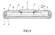
- FIG. 9 is a side sectional view illustrating a locking unit of the portable communication device.
- FIG. 10 is a side sectional view illustrating a state where the portable communication device is not yet operated
- FIG. 11 is an enlarged side sectional view of a portion C of FIG. 10 ;
- FIG. 12 is a view illustrating a state where the locking unit of the portable communication device is operated.
- FIG. 13 is a cutaway plan view illustrating a state where the portable communication device is not operated yet
- FIG. 14 is an enlarged plan view of a portion D of FIG. 13 ;
- FIG. 15 is a cutaway perspective view illustrating a state where the portable communication device is operated.
- FIG. 16 is a cutaway plan view illustrating a state where the portable communication device is operated.
- FIG. 17 is an enlarged plan view of a portion E of FIG. 16 .
- a portable communication device 10 includes a body 20 having a part attaching/detaching section 20 a , a case 30 , a sliding module 40 , a locking unit 50 , and at least one stopper 60 .
- the body 20 is installed within the case 30 to open or close the part attaching/detaching section 20 a as the case 30 slides.
- the case 30 is slidably coupled to the body 20 to open or close the part attaching/detaching section 20 a as the case 30 slides.
- the sliding module 40 is installed between the body 20 and the case 30 to slide the case 30 from the body 20 .
- the locking unit 50 is installed in the body 20 and the case 30 to catch or release the case 30 .
- the stopper 60 is installed in the body 20 and the case 30 to restrict the sliding of the case 30 .
- the case 30 is configured to fully open the entire part attaching/detaching section 20 a having at least one part.
- the part attaching/detaching section 20 a may be one of a battery attaching/detaching section, a memory card attaching/detaching section, and a plurality of connecting jacks, but may be any suitable part attaching/detaching section other than a battery attaching/detaching section, a memory card attaching/detaching section, and a plurality of connecting jacks.
- the body 20 includes first and second body elements 21 and 22 .
- the first body element 21 is coupled to the second body element 22 to include the locking unit 50
- the second body element 22 is coupled to the first body element 21 to include the stopper 60 .
- the case 30 is a rear case made of a metal, but may be any suitable case other than the rear case (for example, an upper case).
- the case 30 is made of aluminum, but may be made of any suitable material other than aluminum (for example, stainless steel)
- the sliding module 40 includes a pair of guide rails 41 and a pair of slide grooves 42 .
- the guide rails 41 are installed at opposite ends of the body 20 to be slidably coupled to the slide grooves 42 and the slide grooves 42 are formed at opposite ends of the case 30 to be slidably coupled to the guide rails 41 .
- the locking unit 50 includes a button 51 , a movable locker 52 , a pair of hooks 53 , and a pair of coil springs 54 .
- the button 51 is installed in the body 20 to be exposed to the outside and be pushed by an external force.
- the movable locker 52 is installed at a lower portion of the button 51 to be caught by a catching recess 31 formed in the case 30 or released therefrom when moved upward or downward as the button 51 is pushed or the case 30 is slid.
- the hooks 53 are formed at opposite ends of the movable locker 52 to contact a support 24 installed in the body 20 and prevent the movable locker 52 from being separated.
- the coil springs 54 are installed at a lower portion of the movable locker 52 to provide resilient forces for moving the movable locker 52 upward and downward.
- an inclined contact surface 52 a is formed in the movable locker 52 to contact the catching recess 31 of the case 30 and guide a caught state of the movable locker 52 .
- the stopper 60 includes first and second stopper recesses 61 and 62 , and a stopper locker 63 .
- the first stopper recess 61 is formed in the case 30 to restrict the sliding of the case 30 at an initial position.
- the second stopper 62 is formed in the case 30 to restrict the sliding of the case 30 at a final position.
- the stopper locker 63 is installed in the body 20 to be detached from the first and second stopper recesses 61 and 62 as the case 30 slides.
- the stopper locker 63 includes a coupler 63 a , a catcher 63 b , a resilient member 63 c , and a support member 63 d .
- the coupler 63 a is coupled to a coupling recess 23 formed in the body 20 .
- the catcher 63 b is formed at a position adjacent to the coupler 63 a to be attached to and detached from the first and second stopper recesses 61 and 62 and to be caught or released due to a deflection generated when the case 30 slides.
- the resilient member 63 c is formed in the catcher 63 b to provide a resilient force for the deflection of the catcher 63 b .
- the support member 63 d is formed in the coupler 63 a to support the deflection of the catcher 63 b.
- the coupler 63 a has a coupling hole to be coupled to a coupling boss 23 a formed in the coupling recess 23 of the body 20 .
- inclined guide surfaces 61 a and 62 a are formed in the first and second stopper recesses 61 and 62 to detachably guide the catcher 63 b of the stopper locker 63 as the case 30 slides, and an inclined surface 70 is formed in the catcher 63 b to face the inclined guide surfaces 61 a and 62 a and guide attachment and detachment of the inclined guide surfaces 61 a and 62 a.
- the portable communication device 10 includes a body 20 having a part attaching/detaching section 20 a , a case 30 , a sliding module 40 , a locking unit 50 , and at least one stopper 60 .
- the part attaching/detaching section 20 a may be exemplified by a battery attaching/detaching section, as described hereinbelow.
- the case 30 is a rear case made of aluminum.
- the sliding module 40 includes a pair of guide rails 41 and a pair of slide grooves 42 .
- the locking unit 50 includes a button 51 , a movable locker 52 , a pair of hooks 53 , and a pair of coil springs 54 .
- the body 20 includes first and second body elements 21 and 22 .
- the locking unit 50 is installed in the first body element 21 , and the hooks 53 contact the support 24 of the first body 21 when coupled to the support 24 of the first body 21 .
- Each of a pair of coil springs 54 are coupled to a lower portion of the movable locker 52 .
- the stopper 60 includes first and second stopper recesses 61 and 62 , and a stopper locker 63 .
- the stopper locker 63 is coupled to a couple recess 23 formed in the second body element 22 .
- the first and second body elements 21 and 22 are coupled to each other, and a pair of guide rails 41 installed at opposite ends of the second body element 22 is slidably coupled to a pair of slide grooves 42 formed at opposite ends of the case 30 .
- the button 51 is moved from the upper side to the lower side and the movable locker 52 is moved together.
- the movable locker 52 is released when separated from the catching recess 31 formed in the case 30 , and the movable locker 52 is moved to an original position again from the lower side to the upper side by a coil spring 54 installed at a lower portion of the movable locker 52 .
- the hooks 53 formed at opposite ends of the movable locker 52 contact a support 24 installed in the first body element 21 and prevent separation of the movable locker 52 at the same time.
- the slide grooves 42 formed at opposite ends of the case 30 are slid by the guide rails 41 installed at opposite ends of the body section 20 .
- the first and second stopper recesses 61 and 62 formed in the case 30 are slid together, and the first stopper recess 61 is separated from a catcher 63 b of the stopper locker 63 .
- An inclined guide surface 61 a formed in the first stopper recess 61 guides separation of the catcher 63 b .
- the catcher 63 b is deflected by a resilient member 63 c when moved on the inclined guide surface 61 a.
- the case 30 is moved from the body 20 to a slide completing position of the case 30 .
- the catcher 63 b is inserted into and caught by the second stopper recess 62 formed in the case 30 to restrict the sliding of the case 30 . Then, the deflected catcher 63 b is moved to an original position again by the resilient member 63 c and is inserted into the second stopper recess 62 .
- the catcher 63 b is guided by and inserted into the inclined guide surface 62 a formed in the second stopper recess 62 . Then, since an inclined surface 70 facing the inclined guide surface 62 a formed in the second stopper recess 62 and guiding attachment and detachment of the inclined guide surface 62 a is formed in the catcher 63 b , the inclined surface 70 guides insertion of the inclined guide surface 62 a and faces the inclined guide surface 62 a at the same time when the catcher 63 b is inserted along the inclined guide surface 62 a.
- the case 30 is slid from the body 20 and opens the battery attaching/detaching section 20 a installed in the body 20 at the same time.
- a battery pack 80 mounted to the battery attaching/detaching section 20 a is separated so that a new battery pack 80 can be coupled.
- the case 30 is slid and the first and second stopper recesses 61 and 62 are moved together at the same time.
- the catcher 63 b is separated from the second stopper recess 62 and is deflected by the resilient member 63 c.
- the catcher 63 b is inserted into the first stopper recess 61 again.
- the deflected catcher 63 b is moved to an original position again by the resilient member 63 c and is inserted into the first stopper recess 61 .
- the inclined surface 70 since the inclined surface 70 is formed in the catcher 63 b , the inclined surface 70 guides insertion of the inclined guide surface 61 a and faces the inclined guide surface 61 a when the catcher 63 b is inserted along the inclined guide surface 61 a of the first stopper recess 61 .
- the catching recess 31 of the case 30 contacts the movable locker 52 , and is guided along a contact guide surface 52 a formed in the movable locker 52 and is caught by the movable locker 52 , restricting movement of the movable locker 52 .
- the movable locker 52 is moved upward and downward while contacting the catching recess 31 .
- the case 30 opens or closes the battery attaching/detaching section 20 a installed in the body 20 when it slides along the body 20 , an appealing outer product design is realized without need for a conventional battery cover to open and close the battery attaching/detaching section 20 a . Moreover, such design further realizes reduced manufacturing costs and reduced number of parts of the product.
- the above-described portable communication device is merely one embodiment of the present invention, that the invention is not limited to a mobile communication terminal. Various types of terminals may employ the present invention.
- the portable communication device of the invention may include without limitation any mobile communication terminals operated based on any known or developing communication protocols, all information and communication devices including without limitation portable multimedia players (PMPs), MP3 players, navigation systems, gaming devices, laptop computers, advertising panels, TVs, digital broadcasting players, personal digital assistants (PDAs), smart phones, electronic devices and multimedia devices, and application devices thereof.
- PMPs portable multimedia players
- MP3 players MP3 players
- navigation systems gaming devices
- gaming devices laptop computers
- advertising panels TVs
- TVs digital broadcasting players
- PDAs personal digital assistants
- smart phones electronic devices and multimedia devices, and application devices thereof.
Abstract
Description
Claims (19)
Applications Claiming Priority (2)
| Application Number | Priority Date | Filing Date | Title |
|---|---|---|---|
| KR1020110069651A KR101850150B1 (en) | 2011-07-13 | 2011-07-13 | Portable communication device |
| KR10-2011-0069651 | 2011-07-13 |
Publications (2)
| Publication Number | Publication Date |
|---|---|
| US20130016464A1 US20130016464A1 (en) | 2013-01-17 |
| US9131038B2 true US9131038B2 (en) | 2015-09-08 |
Family
ID=46642352
Family Applications (1)
| Application Number | Title | Priority Date | Filing Date |
|---|---|---|---|
| US13/546,390 Expired - Fee Related US9131038B2 (en) | 2011-07-13 | 2012-07-11 | Portable communication device |
Country Status (3)
| Country | Link |
|---|---|
| US (1) | US9131038B2 (en) |
| EP (1) | EP2547076B1 (en) |
| KR (1) | KR101850150B1 (en) |
Families Citing this family (8)
| Publication number | Priority date | Publication date | Assignee | Title |
|---|---|---|---|---|
| JP6160982B2 (en) * | 2014-11-10 | 2017-07-12 | トヨタ自動車株式会社 | Manufacturing method of fuel cell stack |
| US10080300B1 (en) * | 2015-12-29 | 2018-09-18 | EMC IP Holding Company LLC | Mechanical latch module |
| US10061367B2 (en) * | 2016-01-22 | 2018-08-28 | Lg Electronics Inc. | Mobile terminal |
| KR200486580Y1 (en) * | 2016-06-23 | 2018-06-07 | 주식회사 아이스픽 | This mobile phone card storage available semi-automatic slide case |
| KR20180001455U (en) * | 2016-11-08 | 2018-05-16 | 허홍만 | smart-phone case with sliding open and shut type credit card keeping part |
| JP7337186B2 (en) * | 2019-03-18 | 2023-09-01 | ケーエムダブリュ・インコーポレーテッド | Antenna clamping device |
| AU2020240972B2 (en) * | 2019-03-18 | 2023-07-20 | Kmw Inc. | Clamping apparatus for antenna |
| KR102195094B1 (en) * | 2019-09-20 | 2020-12-24 | 주식회사 리베르곤 | Escape protection apparatus for a battery pack with dual hook structure and Battery pack charging apparatus having it |
Citations (15)
| Publication number | Priority date | Publication date | Assignee | Title |
|---|---|---|---|---|
| EP0685894A1 (en) | 1994-06-03 | 1995-12-06 | Kokusai Electric Co., Ltd. | A splashproof electronic device |
| US5535437A (en) * | 1991-06-03 | 1996-07-09 | Motorola, Inc. | Portable radio battery latch |
| US20050054397A1 (en) * | 2003-09-08 | 2005-03-10 | Samsung Electronics Co., Ltd. | Portable sliding-type digital communication device and locking apparatus thereof |
| US20050096105A1 (en) * | 2003-10-29 | 2005-05-05 | Benq Corporation | Mobile phone and battery-positioning device thereof |
| US20060148538A1 (en) * | 2004-12-31 | 2006-07-06 | Benq Corporation | Mobile phone with a fastener capable of bidirection movement |
| US20070024233A1 (en) * | 2005-07-28 | 2007-02-01 | Jack Ekchian | Armature type electrical generators for self powered cell phones |
| US20070218961A1 (en) * | 2006-03-17 | 2007-09-20 | Shenzhen Futaihong Precision Industrial Co,.Ltd. | Battery cover assembly |
| WO2008060057A1 (en) | 2006-11-17 | 2008-05-22 | Bluebird Soft Co., Ltd | Mobile terminal |
| KR20090050837A (en) | 2007-11-16 | 2009-05-20 | 삼성전자주식회사 | Battery cover mounting/demounting apparatus portable communication device |
| US20090263713A1 (en) * | 2008-04-18 | 2009-10-22 | Shenzhen Futaihong Precision Industry Co., Ltd. | Battery cover assembly |
| US20100079933A1 (en) * | 2008-09-26 | 2010-04-01 | Shenzhen Futaihong Precision Industry Co., Ltd. | Portable electronic device with chip card ejecting mechanism |
| US20100124697A1 (en) | 2008-11-14 | 2010-05-20 | Shenzhen Futaihong Precision Industry Co., Ltd. | Battery cover mechanism |
| US20110007455A1 (en) * | 2009-07-13 | 2011-01-13 | Shenzhen Futaihong Precision Industry Co., Ltd. | Portable electronic device |
| US20110110022A1 (en) * | 2008-06-19 | 2011-05-12 | Panasonic Corporation | Portable terminal device with waterproof structure |
| US7970444B2 (en) * | 2007-02-28 | 2011-06-28 | Sony Ericsson Mobile Communications Ab | Pivoting mobile terminal |
-
2011
- 2011-07-13 KR KR1020110069651A patent/KR101850150B1/en active IP Right Grant
-
2012
- 2012-07-11 US US13/546,390 patent/US9131038B2/en not_active Expired - Fee Related
- 2012-07-13 EP EP12176241.3A patent/EP2547076B1/en not_active Not-in-force
Patent Citations (15)
| Publication number | Priority date | Publication date | Assignee | Title |
|---|---|---|---|---|
| US5535437A (en) * | 1991-06-03 | 1996-07-09 | Motorola, Inc. | Portable radio battery latch |
| EP0685894A1 (en) | 1994-06-03 | 1995-12-06 | Kokusai Electric Co., Ltd. | A splashproof electronic device |
| US20050054397A1 (en) * | 2003-09-08 | 2005-03-10 | Samsung Electronics Co., Ltd. | Portable sliding-type digital communication device and locking apparatus thereof |
| US20050096105A1 (en) * | 2003-10-29 | 2005-05-05 | Benq Corporation | Mobile phone and battery-positioning device thereof |
| US20060148538A1 (en) * | 2004-12-31 | 2006-07-06 | Benq Corporation | Mobile phone with a fastener capable of bidirection movement |
| US20070024233A1 (en) * | 2005-07-28 | 2007-02-01 | Jack Ekchian | Armature type electrical generators for self powered cell phones |
| US20070218961A1 (en) * | 2006-03-17 | 2007-09-20 | Shenzhen Futaihong Precision Industrial Co,.Ltd. | Battery cover assembly |
| WO2008060057A1 (en) | 2006-11-17 | 2008-05-22 | Bluebird Soft Co., Ltd | Mobile terminal |
| US7970444B2 (en) * | 2007-02-28 | 2011-06-28 | Sony Ericsson Mobile Communications Ab | Pivoting mobile terminal |
| KR20090050837A (en) | 2007-11-16 | 2009-05-20 | 삼성전자주식회사 | Battery cover mounting/demounting apparatus portable communication device |
| US20090263713A1 (en) * | 2008-04-18 | 2009-10-22 | Shenzhen Futaihong Precision Industry Co., Ltd. | Battery cover assembly |
| US20110110022A1 (en) * | 2008-06-19 | 2011-05-12 | Panasonic Corporation | Portable terminal device with waterproof structure |
| US20100079933A1 (en) * | 2008-09-26 | 2010-04-01 | Shenzhen Futaihong Precision Industry Co., Ltd. | Portable electronic device with chip card ejecting mechanism |
| US20100124697A1 (en) | 2008-11-14 | 2010-05-20 | Shenzhen Futaihong Precision Industry Co., Ltd. | Battery cover mechanism |
| US20110007455A1 (en) * | 2009-07-13 | 2011-01-13 | Shenzhen Futaihong Precision Industry Co., Ltd. | Portable electronic device |
Also Published As
| Publication number | Publication date |
|---|---|
| KR101850150B1 (en) | 2018-04-19 |
| US20130016464A1 (en) | 2013-01-17 |
| EP2547076A3 (en) | 2013-04-24 |
| KR20130008946A (en) | 2013-01-23 |
| EP2547076A2 (en) | 2013-01-16 |
| EP2547076B1 (en) | 2018-09-05 |
Similar Documents
| Publication | Publication Date | Title |
|---|---|---|
| US9131038B2 (en) | Portable communication device | |
| US8073510B2 (en) | Mobile communication terminal | |
| US8363036B2 (en) | Stylus retaining mechanism for portable electronic device | |
| KR100536939B1 (en) | Slide type portable terminal | |
| US20140185199A1 (en) | Electronic device with releasable card holder | |
| EP1906631B1 (en) | Semi-automatic sliding device for a portable terminal and portable terminal having the same | |
| US7575452B2 (en) | Slider unit and card connector | |
| US20060180457A1 (en) | Sliding mechanism for use with portable electronic device and method of operating the same | |
| US20100022286A1 (en) | Sliding mechanism and portable electronic device using the same | |
| US8481202B2 (en) | Battery cover assembly | |
| EP1760996A2 (en) | Slide assembly for a portable terminal | |
| US7945299B2 (en) | Multiple torsion spring and semi-automatic sliding device using the same | |
| US8594754B2 (en) | Electronic device | |
| US7319460B2 (en) | Electronic device with retractable stylus | |
| US7837487B2 (en) | Card socket assembly | |
| US7751187B2 (en) | Foldable electronic device | |
| KR200473245Y1 (en) | Case for Mobile Handsets | |
| US8783669B2 (en) | Push-push type stylus eject mechanism | |
| US8477074B2 (en) | Card-type device | |
| US8390602B2 (en) | Stylus retaining mechanism for portable electronic device | |
| US9004549B2 (en) | Locking apparatus for case and case having the same | |
| US20130141337A1 (en) | Keypad fastening apparatus | |
| US8638560B2 (en) | Sliding apparatus for double slide-type portable communication device having locking unit | |
| US8391001B2 (en) | Electronic device and sliding hinge thereof | |
| US8522399B2 (en) | Hinge apparatus for folder-type portable communication device |
Legal Events
| Date | Code | Title | Description |
|---|---|---|---|
| AS | Assignment |
Owner name: SAMSUNG ELECTRONICS CO., LTD., KOREA, REPUBLIC OF Free format text: ASSIGNMENT OF ASSIGNORS INTEREST;ASSIGNORS:KIM, DONG-HAK;PARK, CHAN-SEOB;LEE, DONG-IL;REEL/FRAME:028529/0314 Effective date: 20120328 |
|
| FEPP | Fee payment procedure |
Free format text: PAYOR NUMBER ASSIGNED (ORIGINAL EVENT CODE: ASPN); ENTITY STATUS OF PATENT OWNER: LARGE ENTITY |
|
| ZAAA | Notice of allowance and fees due |
Free format text: ORIGINAL CODE: NOA |
|
| ZAAB | Notice of allowance mailed |
Free format text: ORIGINAL CODE: MN/=. |
|
| STCF | Information on status: patent grant |
Free format text: PATENTED CASE |
|
| MAFP | Maintenance fee payment |
Free format text: PAYMENT OF MAINTENANCE FEE, 4TH YEAR, LARGE ENTITY (ORIGINAL EVENT CODE: M1551); ENTITY STATUS OF PATENT OWNER: LARGE ENTITY Year of fee payment: 4 |
|
| FEPP | Fee payment procedure |
Free format text: MAINTENANCE FEE REMINDER MAILED (ORIGINAL EVENT CODE: REM.); ENTITY STATUS OF PATENT OWNER: LARGE ENTITY |
|
| LAPS | Lapse for failure to pay maintenance fees |
Free format text: PATENT EXPIRED FOR FAILURE TO PAY MAINTENANCE FEES (ORIGINAL EVENT CODE: EXP.); ENTITY STATUS OF PATENT OWNER: LARGE ENTITY |
|
| STCH | Information on status: patent discontinuation |
Free format text: PATENT EXPIRED DUE TO NONPAYMENT OF MAINTENANCE FEES UNDER 37 CFR 1.362 |
|
| FP | Lapsed due to failure to pay maintenance fee |
Effective date: 20230908 |