US9123987B2 - Antenna mounting systems and methods - Google Patents
Antenna mounting systems and methods Download PDFInfo
- Publication number
- US9123987B2 US9123987B2 US13/563,537 US201213563537A US9123987B2 US 9123987 B2 US9123987 B2 US 9123987B2 US 201213563537 A US201213563537 A US 201213563537A US 9123987 B2 US9123987 B2 US 9123987B2
- Authority
- US
- United States
- Prior art keywords
- mounting bracket
- mounting
- mounting plate
- coupling
- protrusion
- Prior art date
- Legal status (The legal status is an assumption and is not a legal conclusion. Google has not performed a legal analysis and makes no representation as to the accuracy of the status listed.)
- Active, expires
Links
Images


Classifications
-
- H—ELECTRICITY
- H01—ELECTRIC ELEMENTS
- H01Q—ANTENNAS, i.e. RADIO AERIALS
- H01Q1/00—Details of, or arrangements associated with, antennas
- H01Q1/12—Supports; Mounting means
- H01Q1/1207—Supports; Mounting means for fastening a rigid aerial element
- H01Q1/1221—Supports; Mounting means for fastening a rigid aerial element onto a wall
-
- F—MECHANICAL ENGINEERING; LIGHTING; HEATING; WEAPONS; BLASTING
- F16—ENGINEERING ELEMENTS AND UNITS; GENERAL MEASURES FOR PRODUCING AND MAINTAINING EFFECTIVE FUNCTIONING OF MACHINES OR INSTALLATIONS; THERMAL INSULATION IN GENERAL
- F16M—FRAMES, CASINGS OR BEDS OF ENGINES, MACHINES OR APPARATUS, NOT SPECIFIC TO ENGINES, MACHINES OR APPARATUS PROVIDED FOR ELSEWHERE; STANDS; SUPPORTS
- F16M13/00—Other supports for positioning apparatus or articles; Means for steadying hand-held apparatus or articles
- F16M13/02—Other supports for positioning apparatus or articles; Means for steadying hand-held apparatus or articles for supporting on, or attaching to, an object, e.g. tree, gate, window-frame, cycle
-
- Y—GENERAL TAGGING OF NEW TECHNOLOGICAL DEVELOPMENTS; GENERAL TAGGING OF CROSS-SECTIONAL TECHNOLOGIES SPANNING OVER SEVERAL SECTIONS OF THE IPC; TECHNICAL SUBJECTS COVERED BY FORMER USPC CROSS-REFERENCE ART COLLECTIONS [XRACs] AND DIGESTS
- Y10—TECHNICAL SUBJECTS COVERED BY FORMER USPC
- Y10T—TECHNICAL SUBJECTS COVERED BY FORMER US CLASSIFICATION
- Y10T29/00—Metal working
- Y10T29/49—Method of mechanical manufacture
- Y10T29/49826—Assembling or joining
-
- Y—GENERAL TAGGING OF NEW TECHNOLOGICAL DEVELOPMENTS; GENERAL TAGGING OF CROSS-SECTIONAL TECHNOLOGIES SPANNING OVER SEVERAL SECTIONS OF THE IPC; TECHNICAL SUBJECTS COVERED BY FORMER USPC CROSS-REFERENCE ART COLLECTIONS [XRACs] AND DIGESTS
- Y10—TECHNICAL SUBJECTS COVERED BY FORMER USPC
- Y10T—TECHNICAL SUBJECTS COVERED BY FORMER US CLASSIFICATION
- Y10T29/00—Metal working
- Y10T29/53—Means to assemble or disassemble
Definitions
- Known methods for coupling antennas with buildings typically involve bolting or screwing the antenna and/or related coupling members directly to a building such that the coupling is not easily reversible. This can cause unwanted and unsightly damage to a building in the circumstance that the attachment needs to be undone. Furthermore, if the antenna and/or related coupling members need to be repaired or replaced, it can delay such maintenance. In some cases, the prior mounting point may even become unusable for attachment of a new antenna.
- an apparatus for coupling an object to a surface may include a mounting plate, a mounting bracket, and a locking plate.
- the mounting plate may include a mounting portion configured to be coupled with the surface, a receptacle portion configured to receive a mounting bracket, and at least one protrusion extending from the mounting portion.
- the mounting bracket may include a backing portion, where the backing portion defines at least one aperture which is configured to receive the at least one protrusion when the mounting bracket is disposed in the receptacle portion of the mounting plate, and a coupling portion, where the coupling portion is configured to be coupled with the object, which may be an antenna.
- the locking plate may be configured to be disposed between at least a portion of the at least one protrusion and at least a portion of the backing portion.
- an apparatus coupling an object to a surface may include a mounting plate, a mounting bracket, and a locking plate.
- the mounting plate may be coupled with the surface, where the mounting plate includes at least one protrusion and a receptacle portion.
- the mounting bracket may be disposed in the receptacle portion of the mounting plate, where the mounting bracket is coupled with the object, and where the at least one protrusion extend through at least one aperture in the mounting bracket.
- the locking plate may be disposed between the at least one protrusion and hold the mounting bracket against the mounting plate.
- a method for coupling an object to a surface may include coupling a mounting plate with the surface.
- the mounting plate may include a receptacle portion configured to receive a mounting bracket and at least one protrusion extending from the mounting portion.
- the method may also include disposing a mounting bracket into the receptacle.
- the method may further include rotating the mounting bracket so that a backing portion of the mounting bracket is flush with the mounting plate and the at least one protrusion extends through apertures in the mounting bracket.
- the method may additionally include disposing a locking plate in between at least a portion of the at least one protrusion and the mounting bracket.
- FIG. 1A is an axonometric view of a mounting plate.
- FIG. 1B is a side view of a mounting plate.
- FIG. 2 is an axonometric view a mounting bracket.
- FIG. 3 is an axonometric view of a locking plate.
- FIG. 4A is an axonometric view of a mounting bracket inserted into the receptacle portion of a mounting plate.
- FIG. 4B is an axonometric view of a mounting bracket fully inserted and rotated in the receptacle portion of a mounting plate.
- FIG. 4C is an axonometric view of a locking plate disposed into the assembly of FIG. 4B .
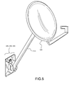
- FIG. 5 is an axonometric view of the assembly of FIG. 4C with a parabolic antenna coupled thereto.
- an apparatus for coupling an object to a surface is provided.
- the object may be a satellite television antenna such as a parabolic antenna or other type of antenna.
- the object or antenna may include related structural coupling members such as a mounting arm. That is, the object or antenna may be coupled with a mounting arm, and the mounting arm may be coupled with the apparatuses described herein.
- the apparatuses described herein may include a mounting plate, a mounting bracket, and a locking plate.
- the mounting plate may include a mounting portion configured to be coupled with the surface, a receptacle portion configured to receive a mounting bracket, and at least one protrusion extending from the mounting portion.
- Each of these pieces may be made from any number of materials, including metals such as steel or aluminum.
- the mounting portion may be configured to be coupled with the surface in any number of ways.
- the mounting plate may have apertures, possibly countersunk or counterbored, allowing mechanical fasteners such as screws or bolts to be used to couple the mounting plate the surface.
- the mounting plate may be glued or otherwise adhered to the surface. These mounting plates may not have apertures. Embodiments that have apertures for mechanical couplings may also be adhered to a surface by merely ignoring the apertures.
- the mounting plate may protrusions on the backside of the plate to allow for coupling with the structure of a building during construction of the building.
- the receptacle portion of the mounting plate may constitute an upturned edge of the mounting portion.
- the receptacle portion may constitute an additional fabrication coupled with the mounting portion.
- the receptacle portion may be shaped so that it is capable of accepting the mounting bracket when the mounting bracket is disposed therein.
- the receptacle portion may be configured to accept an entire bottom edge of the mounting bracket.
- only a portion of the bottom edge of the mounting bracket may be accepted by the receptacle portion.
- the bottom edge of the mounting bracket may have flanges at the ends of the bottom edge, thereby allowing for the bottom edge to be centered when disposed in the receptacle portion.
- the protrusions of the mounting plate may extend away axially and perpendicularly from the front face of the mounting portion (the back face being the face that is adhered/coupled with the surface).
- the protrusions may be mushroom shaped such that the first portion of the protrusion proximate to the front face is narrower than the second portion of the protrusion distal to the front face. While the first and/or second portion of the protrusion may be round, other shapes are possible.
- the first portion may be of a length (away from the front face) equal to or greater than the thickness of the mounting bracket and the locking plate for reasons discussed below. Both the first portion and the second portion may be circular in cross section. Other cross sectional shapes are possible.
- the mounting bracket may include a backing portion and a coupling portion.
- the backing portion may be of a size such that when the mounting bracket is disposed within the receptacle portion of the mounting plate, its size approximately matches the mounting portion (it does not significantly overhang the mounting portion).
- the backing portion may define at least one aperture which may be configured to receive the at least one protrusion when the mounting bracket is disposed in the receptacle portion of the mounting plate. In many embodiments, the number of apertures will match the number of protrusions on the mounting plate.
- the coupling portion of the mounting bracket may have any number of features which allow for the attachment of an object or antenna with the mounting bracket.
- an arm member may couple with the coupling portion, and the object/antenna may couple with the object/antenna. Any number of individual pieces may join the object/antenna with the coupling portion of the mounting bracket.
- the coupling portion may extend away perpendicular to the plane of the backing portion. These or other portions of the coupling portion may define or bracket/surround the outer ends of an edge of the backing portion which is configured to be disposed in the receptacle portion.
- the locking plate may be configured to be disposed between at least a portion of the at least one protrusion and at least a portion of the backing portion when the mounting bracket is disposed in the receptacle portion of the mounting plate and flush thereto.
- the locking plate may include apertures which are configured to go over the mushroom shaped protrusions, and then slide parallel in the plane of the backing portion and mounting portion such that a smaller portion of the apertures engages the narrower portion of the mushroom shaped protrusions. Details of such an embodiment will be discussed below in reference to the figures.
- the bulbous portion of the mushroom shaped protrusions holds the locking plate against the backing portion of the mounting bracket, which is in turn held against the mounting portion of the mounting plate.
- the mounting bracket is secured against the surface to which the mounting plate is secured to. This allows for a reversible connection of the object/antenna to the surface.
- all that is required to remove the object/antenna from the surface is to remove the locking plate, then pull the mounting bracket off the mounting plate.
- the locking plate may include a removal protrusion to assist in removing it from the apparatus. This removal protrusion may be grasped by a tool such as pliers to assist in removal.
- the apparatus may include a mounting plate, a mounting bracket, and a locking plate.
- the mounting plate may be coupled with the surface, where the mounting plate includes at least one protrusion and a receptacle portion.
- the mounting bracket may be disposed in the receptacle portion of the mounting plate, where the mounting bracket is coupled with the object/antenna, and where the at least one protrusion extend through at least one aperture in the mounting bracket.
- the locking plate may be disposed between the at least one protrusion and hold the mounting bracket against the mounting plate.
- a method for coupling an object to a surface is provided. Many of these embodiments will be methods of employing the apparatuses discussed above.
- a kit of the mounting plate, the mounting bracket, and the locking plate will be provided.
- the method may include coupling a mounting plate with the surface.
- the mounting plate may include a receptacle portion configured to receive a mounting bracket and at least one protrusion extending from the mounting portion.
- the method may also include disposing a mounting bracket into the receptacle.
- the method may further include rotating the mounting bracket so that a backing portion of the mounting bracket is flush with the mounting plate and the at least one protrusion extends through apertures in the mounting bracket.
- the method may additionally include disposing a locking plate in between at least a portion of the at least one protrusion and the mounting bracket.
- FIG. 1 an axonometric view of a mounting plate 100 is shown.
- FIG. 1B shows a side view of mounting plate 100 .
- Mounting plate 100 may include a mounting portion 105 and a receptacle portion 110 .
- Receptacle portion 110 in this embodiment is a bent up portion of mounting portion 105 .
- Mounting portion 105 may include two or more counterbored apertures 115 to assist in coupling mounting plate to a surface (multiple possible locations shown in FIG. 1 ). Adhesive may also be used in this embodiment, and apertures 115 ignored. Apertures 115 are counterbored or countersunk to allow for a flush front face 120 of mounting portion 105 to remain after coupling via mechanical fasteners, thereby allowing the backing portion of the mounting bracket to sit flush against front face 120 .
- Mounting portion 105 may also include multiple mushroom shaped protrusions 125 .
- the first portion 130 of protrusions 125 may be smaller in size or diameter than the second portion 135 of protrusions 125 .
- the distance, axially, from front face 120 to second portion 135 may be at least at long as the mounting bracket and locking plate are thick, combined.
- FIG. 2 shows an axonometric view a mounting bracket 200 .
- Mounting bracket 200 may include a backing portion 205 and a mounting portion 210 .
- Mounting portion 210 may include, in this embodiment, two portions 210 A, 210 B which extend perpendicularly away from backing portion 205 .
- Backing portion may include apertures 215 which match, relative to each other, the locations of protrusions 125 . The location of apertures 215 may also match the locations of protrusions 125 relative to the bottom or seat of receptacle portion 110 .
- Mounting portion 210 may include any apertures or mechanisms necessary to couple mounting portion 210 with an object/antenna or other intermediary members coupling to an object/antenna.
- Portions 220 of mounting portion 210 may bracket or frame the bottom edge 225 of backing portion which will be disposed in receptacle portion 110 of mounting plate 100 .
- FIG. 3 shows an axonometric view of a locking plate 300 .
- Locking plate 300 may have upside down keyhole shaped apertures 205 .
- Keyhole shaped apertures 205 may include a first portion 210 at least as large as second portion 135 of protrusions 125 to allow protrusions 125 to pass there-through.
- a second portion 315 of keyhole shaped apertures 205 may be smaller than first portion 310 , but at least as large as first portion 130 of protrusions 125 to allow locking plate to be slid laterally with respect to protrusions 125 thereby engaging second portion 315 around first portion 130 of protrusion 125 , and behind second portion 135 of protrusion 125 .
- Locking plate 300 may also include a locking mechanism 320 to ensure locking plate 300 is not inadvertently dislodged from the apparatus after being engaged.
- locking mechanism 320 is a flat spring with a curved end which allows protrusions 125 to pass through, and become locked once protrusions 123 are engaged with the second portion 315 of keyhole shaped apertures 205 .
- Other types of locking mechanisms may be present in this or other embodiments, including an aperture through locking plate 300 which allows a screw to engage both the locking plate and an additional aperture on mounting plate 100 . Either one of these additional apertures could be threaded to match a locking screw used therein.
- FIG. 4A shows an axonometric view 400 of mounting bracket 200 inserted into receptacle portion 110 of mounting plate 100 . This will usually occur after mounting plate 100 has been coupled with the target surface.
- the fit of lower edge 225 of mounting bracket 200 into receptacle portion 110 may be configured so that various levels of interference between lower edge and receptacle portion 110 are created upon insertion.
- FIG. 4B shows an axonometric view 405 of mounting bracket 200 fully inserted and rotated in receptacle portion 110 of mounting plate 100 .
- portions 220 of mounting portion 210 may bracket bottom edge 225 , and now receptacle portion 110 , thereby centering mounting bracket 200 on mounting plate 100 (protrusions 125 also assist in this matter).
- FIG. 4C shows an axonometric view 410 of a locking plate 415 disposed into the assembly of FIG. 4B .
- locking plate has been disposed onto mounting bracket such that second portion 315 of apertures 305 are behind second portion 135 of protrusions 125 , thereby locking mounting bracket 200 flush into place against mounting plate 100 , and providing a mounting location for an object/antenna (via mounting portion 210 ).
- FIG. 5 shows an axonometric view 500 of the assembly 100 , 200 , 300 of FIG. 4C with a parabolic antenna 500 coupled thereto via an arm 510 .
Abstract
Description
Claims (19)
Priority Applications (5)
| Application Number | Priority Date | Filing Date | Title |
|---|---|---|---|
| US13/563,537 US9123987B2 (en) | 2012-07-31 | 2012-07-31 | Antenna mounting systems and methods |
| EP13825800.9A EP2880354B1 (en) | 2012-07-31 | 2013-07-16 | Apparatus and methods for coupling an object to a surface |
| PCT/US2013/050597 WO2014022087A1 (en) | 2012-07-31 | 2013-07-16 | Antenna mounting systems and methods |
| CA2879717A CA2879717C (en) | 2012-07-31 | 2013-07-16 | Antenna mounting systems and methods |
| MX2015000877A MX354607B (en) | 2012-07-31 | 2013-07-16 | Antenna mounting systems and methods. |
Applications Claiming Priority (1)
| Application Number | Priority Date | Filing Date | Title |
|---|---|---|---|
| US13/563,537 US9123987B2 (en) | 2012-07-31 | 2012-07-31 | Antenna mounting systems and methods |
Publications (2)
| Publication Number | Publication Date |
|---|---|
| US20140033496A1 US20140033496A1 (en) | 2014-02-06 |
| US9123987B2 true US9123987B2 (en) | 2015-09-01 |
Family
ID=50024049
Family Applications (1)
| Application Number | Title | Priority Date | Filing Date |
|---|---|---|---|
| US13/563,537 Active 2033-05-05 US9123987B2 (en) | 2012-07-31 | 2012-07-31 | Antenna mounting systems and methods |
Country Status (5)
| Country | Link |
|---|---|
| US (1) | US9123987B2 (en) |
| EP (1) | EP2880354B1 (en) |
| CA (1) | CA2879717C (en) |
| MX (1) | MX354607B (en) |
| WO (1) | WO2014022087A1 (en) |
Cited By (5)
| Publication number | Priority date | Publication date | Assignee | Title |
|---|---|---|---|---|
| US9565850B2 (en) * | 2015-03-26 | 2017-02-14 | Jeffry Stewart Hagerty | Trap bracket |
| US10526810B1 (en) * | 2017-11-03 | 2020-01-07 | Dion Todd Boos | Flag pole support apparatus |
| US10971794B2 (en) * | 2017-08-15 | 2021-04-06 | Commscope Technologies Llc | Antenna mounting bracket assembly |
| US11388827B2 (en) * | 2020-01-02 | 2022-07-12 | Lite-On Electronics (Guangzhou) Limited | Fixing structure for electronic device |
| USD981831S1 (en) * | 2021-01-18 | 2023-03-28 | Mafi Ab | Fastening device |
Families Citing this family (14)
| Publication number | Priority date | Publication date | Assignee | Title |
|---|---|---|---|---|
| US8819743B2 (en) | 2007-12-19 | 2014-08-26 | Dish Network L.L.C. | Transfer of data related to broadcast programming over a communication network |
| US9337545B2 (en) | 2008-06-20 | 2016-05-10 | Dish Network L.L.C. | Apparatus and systems for mounting an electrical switching device |
| US8780008B2 (en) * | 2008-06-20 | 2014-07-15 | Dish Network L.L.C. | Reinforced mount for an antenna assembly |
| US8802985B2 (en) | 2011-09-07 | 2014-08-12 | Dish Network L.L.C. | In-wall extension apparatus |
| US20130291365A1 (en) * | 2012-05-03 | 2013-11-07 | Fluke Corporation | Accessory mounting system |
| US9123987B2 (en) | 2012-07-31 | 2015-09-01 | Dish Network L.L.C. | Antenna mounting systems and methods |
| CA2885997C (en) | 2012-08-16 | 2017-05-16 | Dish Network L.L.C. | Clamp device for mounting antenna to rail |
| US9625790B2 (en) * | 2014-09-28 | 2017-04-18 | Larry J. Tiefenbrunn | Support base for photographic apparatus |
| KR102376170B1 (en) | 2014-11-04 | 2022-03-21 | 주식회사 케이엠더블유 | Antenna device |
| WO2016072698A1 (en) * | 2014-11-04 | 2016-05-12 | 주식회사 케이엠더블유 | Antenna device |
| EP3254336A1 (en) | 2015-02-26 | 2017-12-13 | Huawei Technologies Co. Ltd. | Radio frequency assembly |
| JP6792076B2 (en) * | 2016-11-16 | 2020-11-25 | ケーエムダブリュ・インコーポレーテッド | Antenna device |
| US10816134B2 (en) * | 2017-11-13 | 2020-10-27 | Arc Off Road Llc | Vehicle door hanger |
| WO2022074511A1 (en) * | 2020-10-06 | 2022-04-14 | 3M Innovative Properties Company | Universal mounting system with prong-bearing wall anchors |
Citations (145)
| Publication number | Priority date | Publication date | Assignee | Title |
|---|---|---|---|---|
| US1994998A (en) | 1934-03-23 | 1935-03-19 | Walter E Hull | Compensating device for compasses |
| US3347505A (en) | 1965-11-17 | 1967-10-17 | Thomas H Vance | Pipe hanger bracket |
| US3392848A (en) | 1966-06-06 | 1968-07-16 | Interlake Steel Corp | Pallet rack |
| US3728796A (en) | 1971-07-22 | 1973-04-24 | L Lobaugh | Center line locator for pipes and the like |
| US4174821A (en) | 1976-06-03 | 1979-11-20 | Fred Levine | Brackets for mounting motors |
| US4203639A (en) | 1978-05-26 | 1980-05-20 | Steelcase, Inc. | Panel wiring system |
| US4358096A (en) | 1979-03-11 | 1982-11-09 | Paton H N | Vehicle suspension system |
| US4361375A (en) | 1980-09-15 | 1982-11-30 | Switchcraft, Inc. | Miniature audio connector |
| US4500064A (en) | 1983-01-12 | 1985-02-19 | Philip Calabro | Mast support assembly |
| US4535689A (en) | 1982-08-25 | 1985-08-20 | Putkowski Ladislao W | Press with wedge |
| US4546549A (en) | 1984-07-05 | 1985-10-15 | Terry Duperon | Adjustable spirit level construction |
| US4589213A (en) | 1985-03-11 | 1986-05-20 | William Woodward | Conduit bending level |
| US4598297A (en) | 1983-10-21 | 1986-07-01 | Hawkins Joel W | Mounting apparatus for satellite dish antennas |
| US4698640A (en) | 1985-08-08 | 1987-10-06 | Gte Sprint Communications Corp | Adjustable platform mounteed horn antenna |
| US4850114A (en) | 1988-05-19 | 1989-07-25 | Vockins David H | Decking spacer |
| US4858878A (en) | 1987-10-21 | 1989-08-22 | Gassaway Mark M | Mount for securing protected articles |
| US4858865A (en) | 1986-10-24 | 1989-08-22 | Air-Loc Schrepfer Ag | Wedge leveling mounting device |
| US4888875A (en) | 1987-11-09 | 1989-12-26 | Strother John M | Level for weightlifting |
| US4908949A (en) | 1987-10-14 | 1990-03-20 | La Maison Dentaire S.A. | Air-bubble level for portable tools |
| US4934706A (en) | 1989-12-11 | 1990-06-19 | Marshall Perry C | Combination lie and shaft position indicator |
| US5002216A (en) * | 1987-07-16 | 1991-03-26 | Gerber Group Ltd. | Invisible mount roof rack |
| US5063679A (en) | 1990-10-10 | 1991-11-12 | Schwandt Bruce E | Protractor bubble level |
| US5149277A (en) | 1988-07-18 | 1992-09-22 | Lemaster Dolan M | Connectivity management system |
| US5154000A (en) | 1992-01-07 | 1992-10-13 | Mahoney Paul R | Conduit bending plane and bend angle indicator |
| US5167075A (en) | 1990-07-19 | 1992-12-01 | All-Pro Level, Inc. | Pipe bending level |
| US5306165A (en) | 1993-01-27 | 1994-04-26 | Jacques Nadeau | Electric distributing system |
| US5359820A (en) | 1993-03-16 | 1994-11-01 | Mckay Michael R | Space saver wall insert for appliances |
| US5574256A (en) | 1994-12-08 | 1996-11-12 | Cottone; Thomas E. | Recessed transformer electrical outlet box with integral telephone line connection |
| US5617680A (en) | 1994-07-21 | 1997-04-08 | Beatty; Douglas | Mounting structure for a satellite dish |
| US5738020A (en) * | 1995-09-12 | 1998-04-14 | Correia; Lewis A. | Lock box and mounting device |
| US5886673A (en) | 1996-06-04 | 1999-03-23 | Thomas; Pat | Apparatus and method for improving portability of satellite antennas |
| US5947752A (en) | 1998-06-09 | 1999-09-07 | Gorden Su | Video data transmission connector and transmission cable mounting arrangement |
| US5963179A (en) | 1997-05-22 | 1999-10-05 | Allen Telecom Inc. | Variable azimuth mounting assembly for panel antennas |
| US5963010A (en) | 1996-10-31 | 1999-10-05 | Hitachi, Ltd. | Battery controller for controlling batteries of different kinds and including battery monitoring means for calculating remaining operation time and an information processing apparatus including such battery controller |
| US5974218A (en) | 1995-04-21 | 1999-10-26 | Hitachi, Ltd. | Method and apparatus for making a digest picture |
| JP2000049516A (en) | 1998-05-29 | 2000-02-18 | Lucent Technol Inc | Intermediate supporting device |
| KR20000047707A (en) | 1998-12-21 | 2000-07-25 | 윤종용 | Antenna mounting apparatus |
| US6180878B1 (en) | 1999-01-29 | 2001-01-30 | Arlington Industries, Inc. | Electrical outlet raceway |
| US6262691B1 (en) | 1999-09-16 | 2001-07-17 | Endgate Corporation | Antenna mounting assembly with installation tool |
| US6281929B1 (en) | 1997-09-23 | 2001-08-28 | Zenith Electronics Corporation | Testing arrangement for decoders |
| US6293035B1 (en) | 1999-04-15 | 2001-09-25 | Kalitec Signalisation Inc. | Sign supporting system |
| US20020003504A1 (en) | 2000-05-15 | 2002-01-10 | Yoshikazu Yoshida | Antenna installation device and satellite radio frequency receiver antenna device |
| US6361007B1 (en) | 2000-01-14 | 2002-03-26 | Xircom Wireless, Inc. | Mounting bracket for PCS and other antennas |
| US6366253B1 (en) * | 2000-09-22 | 2002-04-02 | Hemmingsen, Ii Robert J. | Satellite antenna alignment device |
| US6375161B2 (en) | 1998-11-24 | 2002-04-23 | Norco Industries, Inc. | Scissor jack |
| US6385856B1 (en) | 1999-05-24 | 2002-05-14 | Jeffrey L. Godin | Pipe-bending alignment device |
| US6396459B1 (en) | 2001-06-14 | 2002-05-28 | Timothy A. Pullman | Easy trim dish mount |
| US20020067591A1 (en) | 1999-02-24 | 2002-06-06 | Hisao Tajima | Image display device |
| US6404405B2 (en) | 2000-07-14 | 2002-06-11 | Mitchell Wanat | Releasable mounting for dish satellite antenna |
| US6427348B1 (en) | 2000-07-17 | 2002-08-06 | James Webb | Slope block |
| US20020105476A1 (en) | 2001-02-06 | 2002-08-08 | Overton Steven R. | Antenna quick connect system and method |
| US6438751B1 (en) | 1999-02-18 | 2002-08-20 | Joseph F. Voyticky | Integrated television and internet information system |
| US6445361B2 (en) | 2000-05-29 | 2002-09-03 | Acer Neweb Corp. | Dish antenna rotation apparatus |
| US6450464B1 (en) | 2001-01-12 | 2002-09-17 | Elbert Lee Thomas | Satellite dish stand |
| US6460821B1 (en) | 2000-11-20 | 2002-10-08 | David Andrew Rhudy | DSS uni-mount |
| US20020190172A1 (en) | 2001-06-19 | 2002-12-19 | Oddsen Odd N. | Configurable mount for a peripheral device |
| JP2002374108A (en) | 2001-06-18 | 2002-12-26 | Mitsubishi Electric Corp | Antenna fitting |
| US6532675B2 (en) | 2001-04-18 | 2003-03-18 | Guy Letourneau | Device for measuring the angle of orientation with reference to a known frame of reference between a first object having a first axis and a second remote destination |
| US20030086023A1 (en) | 2001-11-06 | 2003-05-08 | Lg Electronics Inc. | Personal video recorder including a network interface |
| US20030229900A1 (en) | 2002-05-10 | 2003-12-11 | Richard Reisman | Method and apparatus for browsing using multiple coordinated device sets |
| US6727861B2 (en) | 2001-12-31 | 2004-04-27 | Satellite Accessories, Llc | Satellite antenna mounting apparatus and method |
| US6731250B1 (en) | 2002-12-10 | 2004-05-04 | Elliot Berman | Movable window support device for a satellite TV dish |
| US6734830B1 (en) | 2002-09-27 | 2004-05-11 | Comazell Bickham | Portable adjustable stand for satellite dish antennas |
| US6766992B1 (en) | 2003-04-24 | 2004-07-27 | The United States Of America As Represented By The Secretary Of The Navy | Mounting bracket for attachment to flat or cylindrical surfaces |
| US6768474B2 (en) | 2002-12-20 | 2004-07-27 | Spx Corporation | Antenna mounting assembly and method |
| US20040149475A1 (en) | 2003-02-05 | 2004-08-05 | Gorin Thomas Michael | Cable entry box |
| US6777611B2 (en) | 2001-07-11 | 2004-08-17 | Genlyte Thomas Group Llc | Switch/power drop unit for modular wiring system |
| US20040248462A1 (en) | 2003-06-06 | 2004-12-09 | Dyer Jonathan T. | Modular wiring harness and power cord for vending machines |
| US6834435B2 (en) | 2001-08-18 | 2004-12-28 | Steven Turner | Multi-purpose leveling device |
| US20050007241A1 (en) | 2000-01-20 | 2005-01-13 | Kline Paul A. | Method of isolating data in a power line communications network |
| US6873304B1 (en) | 2003-07-17 | 2005-03-29 | Deepak Malhotra | Satellite mast including level |
| US20050101336A1 (en) | 2003-11-10 | 2005-05-12 | Nec Corporation | Mobile communication terminal, mobile communication system and content delivery method |
| US20050101183A1 (en) | 2003-11-07 | 2005-05-12 | Mccoy Dean J. | Providing a bracket assembly to attach a device to a system chassis |
| US6905060B2 (en) * | 2003-10-24 | 2005-06-14 | The Boeing Company | Method and sealant for weld joints |
| US20050250375A1 (en) | 2004-05-10 | 2005-11-10 | Brian Allison | Universal electrical plug and socket |
| US6996911B1 (en) | 2004-03-05 | 2006-02-14 | Dinius Michael J | Combination level and squaring tool |
| US7000746B2 (en) | 2003-08-21 | 2006-02-21 | Woodhead Industries, Inc. | Electric cord reel |
| US20060053447A1 (en) | 2002-06-27 | 2006-03-09 | Openpeak Inc. | Method, system, and computer program product for managing controlled residential or non-residential environments |
| US20060067066A1 (en) | 2004-09-27 | 2006-03-30 | Meier Pascal C | Flexible cable for high-speed interconnect |
| US7027006B2 (en) | 2003-09-24 | 2006-04-11 | Echostar Technologies Corporation | Apparatus and method for mounting a satellite dish to a pole |
| USD522967S1 (en) | 2004-05-07 | 2006-06-13 | St Clair Timothy L | Retractable electrical cord box |
| US7106082B2 (en) | 2002-08-07 | 2006-09-12 | Tokyo Electron Limited | Stage driving apparatus and probe method |
| US7122738B2 (en) | 2004-10-25 | 2006-10-17 | Yazaki Corporation | Electric connection box |
| US20060248553A1 (en) | 2005-04-28 | 2006-11-02 | Microsoft Corporation | Downloading previously aired programs using peer-to-peer networking |
| US7220129B1 (en) | 2005-11-17 | 2007-05-22 | Yazaki Corporation | Electric supply device for slide structure |
| US20070192798A1 (en) | 2005-12-30 | 2007-08-16 | Barrett Morgan | Digital content delivery via virtual private network (VPN) incorporating secured set-top devices |
| US7260920B2 (en) | 2004-04-01 | 2007-08-28 | Weir Kenneth C | Mounting structure for attachment to a building |
| US20070210978A1 (en) | 2006-03-10 | 2007-09-13 | Winegard Company | Satellite dish antenna mounting system |
| US20080117091A1 (en) | 2004-11-08 | 2008-05-22 | Serconet Ltd. | Outlet with analog signal adapter, a method for use thereof and a network using said outlet |
| US20080233794A1 (en) | 2006-08-29 | 2008-09-25 | Adc Telecommunications, Inc. | Threaded connector and patch cord having a threaded connector |
| US7435901B2 (en) | 2005-06-07 | 2008-10-14 | Belkin International, Inc. | Cord management device |
| US20080271331A1 (en) | 2007-05-04 | 2008-11-06 | Allemand James S | Clamping Level Tool |
| US7456802B1 (en) | 2007-09-12 | 2008-11-25 | Donald Bourgeois | Adjustable mounting bracket for satellite dishes |
| US20090052122A1 (en) | 2007-08-09 | 2009-02-26 | Ross Johnson | Modular electrical distribution system for a building |
| US20090056970A1 (en) | 2007-08-29 | 2009-03-05 | The Wiremold Company | Power mat |
| US20090067621A9 (en) | 2006-03-21 | 2009-03-12 | Irdeto Access B.V. | Method of providing an encrypted data stream |
| US20090124113A1 (en) | 2003-09-05 | 2009-05-14 | Newire, Inc. | Flat wire extension cords and extension cord devices |
| US20090150940A1 (en) | 2007-12-05 | 2009-06-11 | Echostar Technologies Corporation | Downloading of an interactive application to a broadcast programming receiver |
| US20090165058A1 (en) | 2007-12-19 | 2009-06-25 | Dish Network L.L.C. | Transfer of data related to broadcast programming over a communication network |
| US7554036B1 (en) | 2008-02-15 | 2009-06-30 | Decosta Thomas J | Sectional plate for wall port incorporating recessed scoop for wire management |
| US7555842B1 (en) | 2005-03-09 | 2009-07-07 | Steve R. Asay | Line leveling tool and method of use |
| US7563131B2 (en) | 2005-08-12 | 2009-07-21 | Lastar, Inc. | Integrated wall plate assembly and premise wiring system incorporating the same |
| US7592719B2 (en) | 2004-02-25 | 2009-09-22 | Panamax | Protection of A/V components |
| US20090251880A1 (en) | 2008-04-02 | 2009-10-08 | Peerless Industries, Inc. | Display mounting system |
| USD603342S1 (en) | 2008-04-24 | 2009-11-03 | Decosta Thomas J | Voltage suppressor recessed receptacle |
| US20090315804A1 (en) | 2008-06-20 | 2009-12-24 | Dish Network L.L.C. | Structures and methods for mounting an antenna |
| US7651353B2 (en) | 2005-10-05 | 2010-01-26 | Group Dekko, Inc. | Modular wall panel electrical assembly |
| US20100046194A1 (en) | 2008-08-19 | 2010-02-25 | Jui-Ming Yang | In-Wall video/audio signal adapter device |
| US7683853B2 (en) | 2006-08-28 | 2010-03-23 | Sean Michaelis | Non-invasive antenna mount |
| US20100075540A1 (en) | 2008-09-19 | 2010-03-25 | Sheng-Hsin Liao | Socket assembly |
| US7692094B1 (en) | 2007-12-17 | 2010-04-06 | Decosta Thomas J | Angularly positionable connector and wall plate combination for sectional plate |
| US7730517B1 (en) | 1998-11-09 | 2010-06-01 | Thomson Licensing S.A. | Signalling of bouquet information in a digital transmission system |
| US20100141379A1 (en) | 2008-12-05 | 2010-06-10 | Tucker Peter T | Modular Rack Controllers for Patching Systems |
| US7739711B2 (en) | 1999-03-29 | 2010-06-15 | The Directv Group, Inc. | Electronic television program guide with calendar tool |
| US20100147580A1 (en) | 2008-12-17 | 2010-06-17 | Jeffrey Koesterich | Extension cord assembly |
| US7741562B2 (en) | 2007-06-19 | 2010-06-22 | Lastar Inc. | Wall plate assembly with integral universal serial bus module |
| US20100219183A1 (en) | 2007-11-19 | 2010-09-02 | Powermat Ltd. | System for inductive power provision within a bounding surface |
| US20110021066A1 (en) | 2009-07-21 | 2011-01-27 | Robert Squires | Power selector inlet |
| US20110032172A1 (en) | 2009-08-04 | 2011-02-10 | Echostar Technologies L.L.C. | Nonconductive antenna mount |
| US20110032175A1 (en) | 2009-08-07 | 2011-02-10 | Samsung Electronics Co., Ltd | Display apparatus and complex entertainment apparatus including the same |
| USD632545S1 (en) | 2010-08-10 | 2011-02-15 | Decosta Thomas J | Sectional plate assembly for a wall port incorporating a reversible slide hood for wire management |
| US7918425B2 (en) | 2008-04-23 | 2011-04-05 | Raytheon Company | Universal antenna mount |
| US20110083399A1 (en) | 2009-10-13 | 2011-04-14 | Dish Network L.L.C. | Structures and methods for mounting an object |
| US20110156984A1 (en) * | 2009-09-14 | 2011-06-30 | Caldwell Steven R | Methods of modifying erect concealed antenna towers and associated modified towers and devices therefor |
| US20110187624A1 (en) | 2008-06-20 | 2011-08-04 | Dish Network L.L.C. | Reinforced mount for an antenna assembly |
| US7997546B1 (en) | 2007-05-07 | 2011-08-16 | Pelco Products, Inc. | Mounting assembly for traffic cameras and other traffic control devices |
| US20110205142A1 (en) | 2010-02-23 | 2011-08-25 | Dish Network L.L.C. | Apparatus for Mounting an Object to a Railing |
| US8011628B1 (en) | 2007-10-09 | 2011-09-06 | Dennis P. Suddeth | Remote reading meter bracket |
| US8015929B2 (en) | 2007-01-25 | 2011-09-13 | Tyner Jeffrey D | Tray apparatus |
| USD647488S1 (en) | 2008-12-03 | 2011-10-25 | Decosta Thomas J | Decor receptacle |
| US20110259883A1 (en) | 2010-04-26 | 2011-10-27 | Decosta Thomas J | Sectional plate for wall port incorporating reversible slide hood for wire management |
| US20120137530A1 (en) | 2009-08-17 | 2012-06-07 | Ji Hae Yun | Level device for a shoe |
| US20120151785A1 (en) | 2010-12-16 | 2012-06-21 | Dish Network L.L.C. | Multi-angle levels and plumbing methods |
| US20120162044A1 (en) * | 2010-12-28 | 2012-06-28 | Dish Network L.L.C. | Systems and Methods for Mounting an Object to an Edge of a Structure |
| US20120256809A1 (en) | 2011-04-06 | 2012-10-11 | Dish Network L.L.C. | Apparatus for mounting a cable connector |
| US20120256496A1 (en) | 2011-04-07 | 2012-10-11 | Decosta Thomas J | Method and apparatus for positioning in-wall power |
| US20120261529A1 (en) | 2011-04-12 | 2012-10-18 | Dish Network L.L.C. | Apparatus and Systems for Mounting an Electrical Switching Device |
| US8339329B2 (en) | 2010-02-09 | 2012-12-25 | Azure Shine International Inc. | Antenna mount |
| US8336221B2 (en) | 2009-10-27 | 2012-12-25 | Milwaukee Electric Tool Corporation | Level |
| US8350153B1 (en) | 2008-07-17 | 2013-01-08 | Decosta Thomas J | Locking mechanism for joining sections |
| US20130056259A1 (en) | 2011-09-07 | 2013-03-07 | Dish Network L.L.C. | In-wall extension apparatus |
| USD678840S1 (en) | 2010-10-30 | 2013-03-26 | Thomas J. DeCosta | Positionable power receptacle |
| USD684935S1 (en) | 2012-09-13 | 2013-06-25 | Thomas J. DeCosta | Recessed electrical box |
| WO2014022087A1 (en) | 2012-07-31 | 2014-02-06 | Dish Network L.L.C. | Antenna mounting systems and methods |
| US20140252182A1 (en) | 2008-06-20 | 2014-09-11 | Dish Network L.L.C. | Apparatus and systems for mounting an electrical switching device |
-
2012
- 2012-07-31 US US13/563,537 patent/US9123987B2/en active Active
-
2013
- 2013-07-16 MX MX2015000877A patent/MX354607B/en active IP Right Grant
- 2013-07-16 EP EP13825800.9A patent/EP2880354B1/en active Active
- 2013-07-16 WO PCT/US2013/050597 patent/WO2014022087A1/en active Application Filing
- 2013-07-16 CA CA2879717A patent/CA2879717C/en active Active
Patent Citations (167)
| Publication number | Priority date | Publication date | Assignee | Title |
|---|---|---|---|---|
| US1994998A (en) | 1934-03-23 | 1935-03-19 | Walter E Hull | Compensating device for compasses |
| US3347505A (en) | 1965-11-17 | 1967-10-17 | Thomas H Vance | Pipe hanger bracket |
| US3392848A (en) | 1966-06-06 | 1968-07-16 | Interlake Steel Corp | Pallet rack |
| US3728796A (en) | 1971-07-22 | 1973-04-24 | L Lobaugh | Center line locator for pipes and the like |
| US4174821A (en) | 1976-06-03 | 1979-11-20 | Fred Levine | Brackets for mounting motors |
| US4203639A (en) | 1978-05-26 | 1980-05-20 | Steelcase, Inc. | Panel wiring system |
| US4203639B1 (en) | 1978-05-26 | 1992-06-30 | L Vanden Hoek Harold | |
| US4358096A (en) | 1979-03-11 | 1982-11-09 | Paton H N | Vehicle suspension system |
| US4361375A (en) | 1980-09-15 | 1982-11-30 | Switchcraft, Inc. | Miniature audio connector |
| US4535689A (en) | 1982-08-25 | 1985-08-20 | Putkowski Ladislao W | Press with wedge |
| US4500064A (en) | 1983-01-12 | 1985-02-19 | Philip Calabro | Mast support assembly |
| US4598297A (en) | 1983-10-21 | 1986-07-01 | Hawkins Joel W | Mounting apparatus for satellite dish antennas |
| US4546549A (en) | 1984-07-05 | 1985-10-15 | Terry Duperon | Adjustable spirit level construction |
| US4589213A (en) | 1985-03-11 | 1986-05-20 | William Woodward | Conduit bending level |
| US4698640A (en) | 1985-08-08 | 1987-10-06 | Gte Sprint Communications Corp | Adjustable platform mounteed horn antenna |
| US4858865A (en) | 1986-10-24 | 1989-08-22 | Air-Loc Schrepfer Ag | Wedge leveling mounting device |
| US5002216A (en) * | 1987-07-16 | 1991-03-26 | Gerber Group Ltd. | Invisible mount roof rack |
| US4908949A (en) | 1987-10-14 | 1990-03-20 | La Maison Dentaire S.A. | Air-bubble level for portable tools |
| US4858878A (en) | 1987-10-21 | 1989-08-22 | Gassaway Mark M | Mount for securing protected articles |
| US4888875A (en) | 1987-11-09 | 1989-12-26 | Strother John M | Level for weightlifting |
| US4850114A (en) | 1988-05-19 | 1989-07-25 | Vockins David H | Decking spacer |
| US5149277A (en) | 1988-07-18 | 1992-09-22 | Lemaster Dolan M | Connectivity management system |
| US4934706A (en) | 1989-12-11 | 1990-06-19 | Marshall Perry C | Combination lie and shaft position indicator |
| US5167075A (en) | 1990-07-19 | 1992-12-01 | All-Pro Level, Inc. | Pipe bending level |
| US5063679A (en) | 1990-10-10 | 1991-11-12 | Schwandt Bruce E | Protractor bubble level |
| US5154000A (en) | 1992-01-07 | 1992-10-13 | Mahoney Paul R | Conduit bending plane and bend angle indicator |
| US5306165A (en) | 1993-01-27 | 1994-04-26 | Jacques Nadeau | Electric distributing system |
| US5359820A (en) | 1993-03-16 | 1994-11-01 | Mckay Michael R | Space saver wall insert for appliances |
| US5617680A (en) | 1994-07-21 | 1997-04-08 | Beatty; Douglas | Mounting structure for a satellite dish |
| US5574256A (en) | 1994-12-08 | 1996-11-12 | Cottone; Thomas E. | Recessed transformer electrical outlet box with integral telephone line connection |
| US5974218A (en) | 1995-04-21 | 1999-10-26 | Hitachi, Ltd. | Method and apparatus for making a digest picture |
| US5738020A (en) * | 1995-09-12 | 1998-04-14 | Correia; Lewis A. | Lock box and mounting device |
| US5886673A (en) | 1996-06-04 | 1999-03-23 | Thomas; Pat | Apparatus and method for improving portability of satellite antennas |
| US5963010A (en) | 1996-10-31 | 1999-10-05 | Hitachi, Ltd. | Battery controller for controlling batteries of different kinds and including battery monitoring means for calculating remaining operation time and an information processing apparatus including such battery controller |
| US5963179A (en) | 1997-05-22 | 1999-10-05 | Allen Telecom Inc. | Variable azimuth mounting assembly for panel antennas |
| US6281929B1 (en) | 1997-09-23 | 2001-08-28 | Zenith Electronics Corporation | Testing arrangement for decoders |
| US6273377B1 (en) | 1998-05-29 | 2001-08-14 | Lucent Technologies Inc. | Device for fixing antenna |
| JP2000049516A (en) | 1998-05-29 | 2000-02-18 | Lucent Technol Inc | Intermediate supporting device |
| US5947752A (en) | 1998-06-09 | 1999-09-07 | Gorden Su | Video data transmission connector and transmission cable mounting arrangement |
| US7730517B1 (en) | 1998-11-09 | 2010-06-01 | Thomson Licensing S.A. | Signalling of bouquet information in a digital transmission system |
| US6375161B2 (en) | 1998-11-24 | 2002-04-23 | Norco Industries, Inc. | Scissor jack |
| KR20000047707A (en) | 1998-12-21 | 2000-07-25 | 윤종용 | Antenna mounting apparatus |
| US7106273B1 (en) | 1998-12-21 | 2006-09-12 | Samsung Electronics Co., Ltd. | Antenna mounting apparatus |
| US6180878B1 (en) | 1999-01-29 | 2001-01-30 | Arlington Industries, Inc. | Electrical outlet raceway |
| US6438751B1 (en) | 1999-02-18 | 2002-08-20 | Joseph F. Voyticky | Integrated television and internet information system |
| US20020067591A1 (en) | 1999-02-24 | 2002-06-06 | Hisao Tajima | Image display device |
| US7739711B2 (en) | 1999-03-29 | 2010-06-15 | The Directv Group, Inc. | Electronic television program guide with calendar tool |
| US6293035B1 (en) | 1999-04-15 | 2001-09-25 | Kalitec Signalisation Inc. | Sign supporting system |
| US6385856B1 (en) | 1999-05-24 | 2002-05-14 | Jeffrey L. Godin | Pipe-bending alignment device |
| US6262691B1 (en) | 1999-09-16 | 2001-07-17 | Endgate Corporation | Antenna mounting assembly with installation tool |
| US6361007B1 (en) | 2000-01-14 | 2002-03-26 | Xircom Wireless, Inc. | Mounting bracket for PCS and other antennas |
| US20050007241A1 (en) | 2000-01-20 | 2005-01-13 | Kline Paul A. | Method of isolating data in a power line communications network |
| US20020003504A1 (en) | 2000-05-15 | 2002-01-10 | Yoshikazu Yoshida | Antenna installation device and satellite radio frequency receiver antenna device |
| US6445361B2 (en) | 2000-05-29 | 2002-09-03 | Acer Neweb Corp. | Dish antenna rotation apparatus |
| US6404405B2 (en) | 2000-07-14 | 2002-06-11 | Mitchell Wanat | Releasable mounting for dish satellite antenna |
| US6427348B1 (en) | 2000-07-17 | 2002-08-06 | James Webb | Slope block |
| US6366253B1 (en) * | 2000-09-22 | 2002-04-02 | Hemmingsen, Ii Robert J. | Satellite antenna alignment device |
| US6460821B1 (en) | 2000-11-20 | 2002-10-08 | David Andrew Rhudy | DSS uni-mount |
| US6450464B1 (en) | 2001-01-12 | 2002-09-17 | Elbert Lee Thomas | Satellite dish stand |
| US20020105476A1 (en) | 2001-02-06 | 2002-08-08 | Overton Steven R. | Antenna quick connect system and method |
| US6532675B2 (en) | 2001-04-18 | 2003-03-18 | Guy Letourneau | Device for measuring the angle of orientation with reference to a known frame of reference between a first object having a first axis and a second remote destination |
| US6396459B1 (en) | 2001-06-14 | 2002-05-28 | Timothy A. Pullman | Easy trim dish mount |
| JP2002374108A (en) | 2001-06-18 | 2002-12-26 | Mitsubishi Electric Corp | Antenna fitting |
| US20020190172A1 (en) | 2001-06-19 | 2002-12-19 | Oddsen Odd N. | Configurable mount for a peripheral device |
| US6777611B2 (en) | 2001-07-11 | 2004-08-17 | Genlyte Thomas Group Llc | Switch/power drop unit for modular wiring system |
| US6834435B2 (en) | 2001-08-18 | 2004-12-28 | Steven Turner | Multi-purpose leveling device |
| US20030086023A1 (en) | 2001-11-06 | 2003-05-08 | Lg Electronics Inc. | Personal video recorder including a network interface |
| US6727861B2 (en) | 2001-12-31 | 2004-04-27 | Satellite Accessories, Llc | Satellite antenna mounting apparatus and method |
| US20050001781A1 (en) | 2001-12-31 | 2005-01-06 | Antoine Mark J. | Satellite antenna mounting apparatus and method |
| US20030229900A1 (en) | 2002-05-10 | 2003-12-11 | Richard Reisman | Method and apparatus for browsing using multiple coordinated device sets |
| US20100031295A1 (en) | 2002-06-27 | 2010-02-04 | Openpeak Inc. | Method, system, and computer program product for managing controlled residential or non-residential environments |
| US20060053447A1 (en) | 2002-06-27 | 2006-03-09 | Openpeak Inc. | Method, system, and computer program product for managing controlled residential or non-residential environments |
| US7106082B2 (en) | 2002-08-07 | 2006-09-12 | Tokyo Electron Limited | Stage driving apparatus and probe method |
| US6734830B1 (en) | 2002-09-27 | 2004-05-11 | Comazell Bickham | Portable adjustable stand for satellite dish antennas |
| US6731250B1 (en) | 2002-12-10 | 2004-05-04 | Elliot Berman | Movable window support device for a satellite TV dish |
| US6768474B2 (en) | 2002-12-20 | 2004-07-27 | Spx Corporation | Antenna mounting assembly and method |
| US20040149475A1 (en) | 2003-02-05 | 2004-08-05 | Gorin Thomas Michael | Cable entry box |
| US6766992B1 (en) | 2003-04-24 | 2004-07-27 | The United States Of America As Represented By The Secretary Of The Navy | Mounting bracket for attachment to flat or cylindrical surfaces |
| US20040248462A1 (en) | 2003-06-06 | 2004-12-09 | Dyer Jonathan T. | Modular wiring harness and power cord for vending machines |
| US6873304B1 (en) | 2003-07-17 | 2005-03-29 | Deepak Malhotra | Satellite mast including level |
| US7057575B2 (en) | 2003-07-17 | 2006-06-06 | Deepak Malhotra | Method of installing a satellite dish and satellite dish mast |
| US7000746B2 (en) | 2003-08-21 | 2006-02-21 | Woodhead Industries, Inc. | Electric cord reel |
| US20090124113A1 (en) | 2003-09-05 | 2009-05-14 | Newire, Inc. | Flat wire extension cords and extension cord devices |
| US7027006B2 (en) | 2003-09-24 | 2006-04-11 | Echostar Technologies Corporation | Apparatus and method for mounting a satellite dish to a pole |
| US7253785B2 (en) | 2003-09-24 | 2007-08-07 | Echostar Technologies Corporation | Apparatus and method for mounting a satellite dish to a pole |
| US7460081B2 (en) | 2003-09-24 | 2008-12-02 | Echostar Technologies L.L.C. | Apparatus and method for mounting a satellite dish to a pole |
| US6905060B2 (en) * | 2003-10-24 | 2005-06-14 | The Boeing Company | Method and sealant for weld joints |
| US20050101183A1 (en) | 2003-11-07 | 2005-05-12 | Mccoy Dean J. | Providing a bracket assembly to attach a device to a system chassis |
| US20050101336A1 (en) | 2003-11-10 | 2005-05-12 | Nec Corporation | Mobile communication terminal, mobile communication system and content delivery method |
| US7592719B2 (en) | 2004-02-25 | 2009-09-22 | Panamax | Protection of A/V components |
| US6996911B1 (en) | 2004-03-05 | 2006-02-14 | Dinius Michael J | Combination level and squaring tool |
| US7260920B2 (en) | 2004-04-01 | 2007-08-28 | Weir Kenneth C | Mounting structure for attachment to a building |
| USD522967S1 (en) | 2004-05-07 | 2006-06-13 | St Clair Timothy L | Retractable electrical cord box |
| US20050250375A1 (en) | 2004-05-10 | 2005-11-10 | Brian Allison | Universal electrical plug and socket |
| US20060067066A1 (en) | 2004-09-27 | 2006-03-30 | Meier Pascal C | Flexible cable for high-speed interconnect |
| US7122738B2 (en) | 2004-10-25 | 2006-10-17 | Yazaki Corporation | Electric connection box |
| US20080117091A1 (en) | 2004-11-08 | 2008-05-22 | Serconet Ltd. | Outlet with analog signal adapter, a method for use thereof and a network using said outlet |
| US7555842B1 (en) | 2005-03-09 | 2009-07-07 | Steve R. Asay | Line leveling tool and method of use |
| US20060248553A1 (en) | 2005-04-28 | 2006-11-02 | Microsoft Corporation | Downloading previously aired programs using peer-to-peer networking |
| US7435901B2 (en) | 2005-06-07 | 2008-10-14 | Belkin International, Inc. | Cord management device |
| US7563131B2 (en) | 2005-08-12 | 2009-07-21 | Lastar, Inc. | Integrated wall plate assembly and premise wiring system incorporating the same |
| US7651353B2 (en) | 2005-10-05 | 2010-01-26 | Group Dekko, Inc. | Modular wall panel electrical assembly |
| US7220129B1 (en) | 2005-11-17 | 2007-05-22 | Yazaki Corporation | Electric supply device for slide structure |
| US20070192798A1 (en) | 2005-12-30 | 2007-08-16 | Barrett Morgan | Digital content delivery via virtual private network (VPN) incorporating secured set-top devices |
| US20070210978A1 (en) | 2006-03-10 | 2007-09-13 | Winegard Company | Satellite dish antenna mounting system |
| US20090067621A9 (en) | 2006-03-21 | 2009-03-12 | Irdeto Access B.V. | Method of providing an encrypted data stream |
| US7683853B2 (en) | 2006-08-28 | 2010-03-23 | Sean Michaelis | Non-invasive antenna mount |
| US20100177010A1 (en) | 2006-08-28 | 2010-07-15 | Sean Michaelis | Non-Invasive Antenna Mount |
| US20080233794A1 (en) | 2006-08-29 | 2008-09-25 | Adc Telecommunications, Inc. | Threaded connector and patch cord having a threaded connector |
| US8015929B2 (en) | 2007-01-25 | 2011-09-13 | Tyner Jeffrey D | Tray apparatus |
| US20080271331A1 (en) | 2007-05-04 | 2008-11-06 | Allemand James S | Clamping Level Tool |
| US8061051B2 (en) | 2007-05-04 | 2011-11-22 | Swanson Tool Company, Inc. | Clamping level tool |
| US7997546B1 (en) | 2007-05-07 | 2011-08-16 | Pelco Products, Inc. | Mounting assembly for traffic cameras and other traffic control devices |
| US7741562B2 (en) | 2007-06-19 | 2010-06-22 | Lastar Inc. | Wall plate assembly with integral universal serial bus module |
| US20090052122A1 (en) | 2007-08-09 | 2009-02-26 | Ross Johnson | Modular electrical distribution system for a building |
| US7648379B2 (en) | 2007-08-09 | 2010-01-19 | Haworth, Inc. | Modular electrical distribution system for a building |
| US20090056970A1 (en) | 2007-08-29 | 2009-03-05 | The Wiremold Company | Power mat |
| US7456802B1 (en) | 2007-09-12 | 2008-11-25 | Donald Bourgeois | Adjustable mounting bracket for satellite dishes |
| US8011628B1 (en) | 2007-10-09 | 2011-09-06 | Dennis P. Suddeth | Remote reading meter bracket |
| US20100219183A1 (en) | 2007-11-19 | 2010-09-02 | Powermat Ltd. | System for inductive power provision within a bounding surface |
| US20090150940A1 (en) | 2007-12-05 | 2009-06-11 | Echostar Technologies Corporation | Downloading of an interactive application to a broadcast programming receiver |
| US7692094B1 (en) | 2007-12-17 | 2010-04-06 | Decosta Thomas J | Angularly positionable connector and wall plate combination for sectional plate |
| US8819743B2 (en) | 2007-12-19 | 2014-08-26 | Dish Network L.L.C. | Transfer of data related to broadcast programming over a communication network |
| US20090165058A1 (en) | 2007-12-19 | 2009-06-25 | Dish Network L.L.C. | Transfer of data related to broadcast programming over a communication network |
| US20140366078A1 (en) | 2007-12-19 | 2014-12-11 | Dish Network L.L.C. | Transfer of data related to broadcast programming over a communication network |
| US7554036B1 (en) | 2008-02-15 | 2009-06-30 | Decosta Thomas J | Sectional plate for wall port incorporating recessed scoop for wire management |
| US20090251880A1 (en) | 2008-04-02 | 2009-10-08 | Peerless Industries, Inc. | Display mounting system |
| US7918425B2 (en) | 2008-04-23 | 2011-04-05 | Raytheon Company | Universal antenna mount |
| USD603342S1 (en) | 2008-04-24 | 2009-11-03 | Decosta Thomas J | Voltage suppressor recessed receptacle |
| US8081139B2 (en) | 2008-06-20 | 2011-12-20 | Dish Network L.L.C. | Structures and methods for mounting an antenna |
| US8780008B2 (en) | 2008-06-20 | 2014-07-15 | Dish Network L.L.C. | Reinforced mount for an antenna assembly |
| US20090315804A1 (en) | 2008-06-20 | 2009-12-24 | Dish Network L.L.C. | Structures and methods for mounting an antenna |
| US20110187624A1 (en) | 2008-06-20 | 2011-08-04 | Dish Network L.L.C. | Reinforced mount for an antenna assembly |
| US20140252182A1 (en) | 2008-06-20 | 2014-09-11 | Dish Network L.L.C. | Apparatus and systems for mounting an electrical switching device |
| US8350153B1 (en) | 2008-07-17 | 2013-01-08 | Decosta Thomas J | Locking mechanism for joining sections |
| US20100046194A1 (en) | 2008-08-19 | 2010-02-25 | Jui-Ming Yang | In-Wall video/audio signal adapter device |
| US20100075540A1 (en) | 2008-09-19 | 2010-03-25 | Sheng-Hsin Liao | Socket assembly |
| USD647488S1 (en) | 2008-12-03 | 2011-10-25 | Decosta Thomas J | Decor receptacle |
| US20100141379A1 (en) | 2008-12-05 | 2010-06-10 | Tucker Peter T | Modular Rack Controllers for Patching Systems |
| US20100147580A1 (en) | 2008-12-17 | 2010-06-17 | Jeffrey Koesterich | Extension cord assembly |
| US20110021066A1 (en) | 2009-07-21 | 2011-01-27 | Robert Squires | Power selector inlet |
| US20110032172A1 (en) | 2009-08-04 | 2011-02-10 | Echostar Technologies L.L.C. | Nonconductive antenna mount |
| US20110032175A1 (en) | 2009-08-07 | 2011-02-10 | Samsung Electronics Co., Ltd | Display apparatus and complex entertainment apparatus including the same |
| US20120137530A1 (en) | 2009-08-17 | 2012-06-07 | Ji Hae Yun | Level device for a shoe |
| US20110156984A1 (en) * | 2009-09-14 | 2011-06-30 | Caldwell Steven R | Methods of modifying erect concealed antenna towers and associated modified towers and devices therefor |
| US20110083399A1 (en) | 2009-10-13 | 2011-04-14 | Dish Network L.L.C. | Structures and methods for mounting an object |
| US8336221B2 (en) | 2009-10-27 | 2012-12-25 | Milwaukee Electric Tool Corporation | Level |
| US8339329B2 (en) | 2010-02-09 | 2012-12-25 | Azure Shine International Inc. | Antenna mount |
| US20110205142A1 (en) | 2010-02-23 | 2011-08-25 | Dish Network L.L.C. | Apparatus for Mounting an Object to a Railing |
| US8462075B2 (en) | 2010-02-23 | 2013-06-11 | Dish Network L.L.C. | Apparatus for mounting an object to a railing |
| US8698692B2 (en) | 2010-02-23 | 2014-04-15 | Dish Network L.L.C. | Apparatus for mounting an object to a railing |
| US20130256480A1 (en) | 2010-02-23 | 2013-10-03 | Dish Network, L.L.C. | Apparatus for mounting an object to a railing |
| US20110259883A1 (en) | 2010-04-26 | 2011-10-27 | Decosta Thomas J | Sectional plate for wall port incorporating reversible slide hood for wire management |
| USD632545S1 (en) | 2010-08-10 | 2011-02-15 | Decosta Thomas J | Sectional plate assembly for a wall port incorporating a reversible slide hood for wire management |
| USD678840S1 (en) | 2010-10-30 | 2013-03-26 | Thomas J. DeCosta | Positionable power receptacle |
| US8646186B2 (en) | 2010-12-16 | 2014-02-11 | Dish Network L.L.C. | Multi-angle levels and plumbing methods |
| US20120151785A1 (en) | 2010-12-16 | 2012-06-21 | Dish Network L.L.C. | Multi-angle levels and plumbing methods |
| US20140090260A1 (en) | 2010-12-16 | 2014-04-03 | Dish Network L.L.C. | Multi-angle levels and plumbing methods |
| US20120162044A1 (en) * | 2010-12-28 | 2012-06-28 | Dish Network L.L.C. | Systems and Methods for Mounting an Object to an Edge of a Structure |
| US20120256809A1 (en) | 2011-04-06 | 2012-10-11 | Dish Network L.L.C. | Apparatus for mounting a cable connector |
| US20120256496A1 (en) | 2011-04-07 | 2012-10-11 | Decosta Thomas J | Method and apparatus for positioning in-wall power |
| US20120261529A1 (en) | 2011-04-12 | 2012-10-18 | Dish Network L.L.C. | Apparatus and Systems for Mounting an Electrical Switching Device |
| US8907862B2 (en) | 2011-04-12 | 2014-12-09 | Dish Network L.L.C. | Apparatus and systems for mounting an electrical switching device |
| US20140174816A1 (en) | 2011-09-07 | 2014-06-26 | Dish Network L.L.C. | In-wall extension apparatus |
| US20130056259A1 (en) | 2011-09-07 | 2013-03-07 | Dish Network L.L.C. | In-wall extension apparatus |
| WO2014022087A1 (en) | 2012-07-31 | 2014-02-06 | Dish Network L.L.C. | Antenna mounting systems and methods |
| USD684935S1 (en) | 2012-09-13 | 2013-06-25 | Thomas J. DeCosta | Recessed electrical box |
Non-Patent Citations (57)
| Title |
|---|
| "Powerbridge In-Wall Power Extension System Home," accessed at http://www.powerbridgesolution.com on Sep. 7, 2011, 4 pages. |
| Author Unknown, "BMI Measuring Instruments," Accessed on Mar. 13, 2011, 9 pages. |
| Author Unknown, "Checkpoint U6 V-Groove Level," Chads Tool Box.com, Accessed Mar. 13, 2011, 6 pages. |
| Author Unknown, "Stanley Hand Tools, 77-009-IntelliPoint Plus Level," Accessed Mar. 13, 2011, 1 page. |
| Author Unknown, Treestand Manual, Locon Treestands, LLC, Waterford, Ohio, known to exist on Oct. 13, 2009, 2 pages. Accessed at http://www.locontreestands . . . |
| Definition of Curve-Merriam Webster. * |
| Definition of Integral-Merriam Webster. * |
| Home Depot, "PowerBridge Ultra Low Profile In-Wall System", Oct. 18, 2013, 2 pages. Retrieved from: http://www.homedepot.com/catalog/pdfImages/ef/ef60a932-d90e-4a49-aa33-576da0d6feb6.pdf. |
| Intellectual Property Office of the Republic of China (Taiwan) for ROC Pat App. No. 097149159, Final Office Action dated Dec. 13, 2012, 9 pages. |
| Intellectual Property Office of the Republic of China (Taiwan) for ROC Pat App. No. 097149159, Office Action dated Sep. 19, 2014, 20 pages. |
| International Preliminary Report on Patentability for PCT/US2013/050597 mailed Feb. 12, 2015, 6 pages. |
| International Search Report and Written Opinion of PCT/US2008/086423 mailed on May 11, 2008, 14 pages. |
| International Search Report and Written Opinion of PCT/US2010/052431, mailed Jun. 10, 2011, 7 pages. |
| International Search Report and Written Opinion of PCT/US2013/050597 mailed Jan. 10, 2014, 17 pages. |
| Legrand, "Flat SCreen TV Cord and Cable Power Kit-CMK70," 2011, 1 page. |
| Midlite Corporation, "The Power Jumper, HDTV Power Relocation Kit," Nov. 10, 2011, www.Midlite.com, 1 page. |
| Powerbridge, "3D Power Cable Total Solution Connector Kit Model #TSCK Power Extension Cable Mangement," 2 pages. |
| Sewell, "DataComm Flat Panel TV Cable Organizer Remodeling Kit with Power Outlet", Feb. 13, 2009, 1 page. Retrieved from: http://sewelldirect.com/Recessed-Cable-Plate-Remodeling-Kit-with-Electrical-Outlet.asp. |
| U.S. Appl. No. 12/328,082, filed Dec. 4, 2008, Final Office Action mailed Dec. 5, 2013, 13 pages. |
| U.S. Appl. No. 12/328,082, filed Dec. 4, 2008, Final Office Action mailed Oct. 26, 2012, 16 pages. |
| U.S. Appl. No. 12/328,082, filed Dec. 4, 2008, Non Final Office Action mailed Apr. 20, 2012, 13 pages. |
| U.S. Appl. No. 12/328,082, filed Dec. 4, 2008, Non Final Office Action mailed Jan. 14, 2011, 19 pages. |
| U.S. Appl. No. 12/328,082, filed Dec. 4, 2008, Non Final Office Action mailed Jul. 8, 2013, 16 pages. |
| U.S. Appl. No. 12/328,082, filed Dec. 4, 2008, Non Final Office Action mailed Nov. 15, 2011, 18 pages. |
| U.S. Appl. No. 12/328,082, filed Dec. 4, 2008, Notice of Allowance mailed Apr. 16, 2014, 24 pages. |
| U.S. Appl. No. 12/483,016, filed Jun. 11, 2009, Notice of Allowance mailed Nov. 8, 2011, 8 pages. |
| U.S. Appl. No. 12/578,367, filed Oct. 13, 2009, Final Office Action mailed Jan. 31, 2012, 11 pages. |
| U.S. Appl. No. 12/578,367, filed Oct. 13, 2009, Final Office Action mailed Nov. 19, 2012, 10 pages. |
| U.S. Appl. No. 12/578,367, filed Oct. 13, 2009, Non-Final Office Action mailed May 14, 2012, 12 pages. |
| U.S. Appl. No. 12/578,367, filed Oct. 13, 2009, Non-Final Office Action mailed Sep. 20, 2011, 21 pages. |
| U.S. Appl. No. 12/711,103, filed Feb. 23, 2010, Non-Final Office Action mailed Aug. 1, 2012, 16 pages. |
| U.S. Appl. No. 12/711,103, filed Feb. 23, 2010, Notice of Allowance mailed Feb. 12, 2013, 13 pages. |
| U.S. Appl. No. 12/970,749, filed Dec. 16, 2010, Final Office Action mailed Feb. 6, 2013, 15 pages. |
| U.S. Appl. No. 12/970,749, filed Dec. 16, 2010, Non-Final Office Action mailed May 16, 2013, 13 pages. |
| U.S. Appl. No. 12/970,749, filed Dec. 16, 2010, Non-Final Office Action mailed Sep. 14, 2012, 16 pages. |
| U.S. Appl. No. 12/970,749, filed Dec. 16, 2010, Notice of Allowance mailed Apr. 16, 2014, 24 pages. |
| U.S. Appl. No. 12/970,749, filed Dec. 16, 2010, Notice of Allowance mailed Sep. 5, 2013, 9 pages. |
| U.S. Appl. No. 12/979,597, filed Dec. 28, 2010, Final Office Action mailed Sep. 17, 2014, 16 pages. |
| U.S. Appl. No. 12/979,597, filed Dec. 28, 2010, Non Final Office Action mailed Mar. 30, 2015, 17 pages. |
| U.S. Appl. No. 12/979,597, filed Dec. 28, 2010, Non-Final Office Action mailed Mar. 28, 2014, 12 pages. |
| U.S. Appl. No. 13/081,364, filed Apr. 6, 2011, Non-Final Office Action mailed Apr. 25, 2013, 12 pages. |
| U.S. Appl. No. 13/084,632, filed Apr. 12, 2011, Non-Final Rejection mailed Jun. 3, 2013, 9 pages. |
| U.S. Appl. No. 13/084,632, filed Apr. 12, 2011, Notice of Allowance mailed Mar. 6, 2014, 15 pages. |
| U.S. Appl. No. 13/084,632, filed Apr. 12, 2011, Notice of Allowance mailed Nov. 18, 2013, 23 pages. |
| U.S. Appl. No. 13/085,210, filed Apr. 12, 2011 Final Office Action mailed Oct. 25, 2013, 12 pages. |
| U.S. Appl. No. 13/085,210, filed Apr. 12, 2011 Non-Final Office Action mailed Mar. 27, 2013, 11 pages. |
| U.S. Appl. No. 13/085,210, filed Apr. 12, 2011, Notice of Allowance mailed Aug. 8, 2014, 20 pages. |
| U.S. Appl. No. 13/226,929, filed Sep. 7, 2011, Final Office Action mailed Feb. 12, 2014, 30 pages. |
| U.S. Appl. No. 13/226,929, filed Sep. 7, 2011, Non-Final Office Action mailed Jun. 28, 2013, 31 pages. |
| U.S. Appl. No. 13/226,929, filed Sep. 7, 2011, Notice of Allowance mailed Mar. 31, 2014, 16 pages. |
| U.S. Appl. No. 13/893,304, filed May 13, 2013, Non-Final Office Action mailed Aug. 1, 2013, 10 pages. |
| U.S. Appl. No. 13/893,304, filed May 13, 2013, Notice of Allowance mailed Dec. 2, 2013, 23 pages. |
| U.S. Appl. No. 14/098,294, filed Dec. 5, 2013, Non Final Office Action mailed Mar. 13, 2014, 15 pages. |
| U.S. Appl. No. 14/098,294, filed Dec. 5, 2013, Notice of Allowance mailed Jul. 30, 2014, 21 pages. |
| U.S. Appl. No. 14/188,408, filed Feb. 24, 2014 Non-Final Office Action mailed May 21, 2015, 23 pages. |
| U.S. Appl. No. 14/193,641, filed Feb. 28, 2014, Non-Final Office Action mailed Feb. 28, 2014, 36 pages. |
| U.S. Appl. No. 14/465,588, filed Aug. 21, 2014, Non-Final Office Action mailed May 7, 2015, 22 pages. |
Cited By (5)
| Publication number | Priority date | Publication date | Assignee | Title |
|---|---|---|---|---|
| US9565850B2 (en) * | 2015-03-26 | 2017-02-14 | Jeffry Stewart Hagerty | Trap bracket |
| US10971794B2 (en) * | 2017-08-15 | 2021-04-06 | Commscope Technologies Llc | Antenna mounting bracket assembly |
| US10526810B1 (en) * | 2017-11-03 | 2020-01-07 | Dion Todd Boos | Flag pole support apparatus |
| US11388827B2 (en) * | 2020-01-02 | 2022-07-12 | Lite-On Electronics (Guangzhou) Limited | Fixing structure for electronic device |
| USD981831S1 (en) * | 2021-01-18 | 2023-03-28 | Mafi Ab | Fastening device |
Also Published As
| Publication number | Publication date |
|---|---|
| EP2880354B1 (en) | 2017-06-28 |
| US20140033496A1 (en) | 2014-02-06 |
| CA2879717A1 (en) | 2014-02-06 |
| EP2880354A4 (en) | 2016-03-30 |
| CA2879717C (en) | 2019-04-30 |
| WO2014022087A1 (en) | 2014-02-06 |
| EP2880354A1 (en) | 2015-06-10 |
| MX354607B (en) | 2018-03-13 |
| MX2015000877A (en) | 2015-05-07 |
Similar Documents
| Publication | Publication Date | Title |
|---|---|---|
| US9123987B2 (en) | Antenna mounting systems and methods | |
| US11811359B2 (en) | Solar module mounting system | |
| US20150102194A1 (en) | Solar Panel Rooftop Mounting and Grounding Device | |
| EP4227600A1 (en) | Solar module mounting system | |
| EP2797487B1 (en) | Antenna assembly mounting system | |
| US20150101997A1 (en) | Solar Panel Rooftop Mounting and Grounding Device | |
| KR20190018450A (en) | Mounting clips Mounting rails, mounting brackets and solar modules | |
| US20050135896A1 (en) | Push-on screw-off attachment device | |
| US10720877B2 (en) | Photovoltaic mounting system for solar tracker array | |
| CN112970193A (en) | System for mounting solar panels | |
| EP3099984B1 (en) | Solar photovoltaic module clamping system and solar carport | |
| US20170040934A1 (en) | Connecting solar modules | |
| US20100066633A1 (en) | Variable angle mount for attaching a mast to a structure | |
| CN113464371A (en) | Method and tool for assembling tower elements | |
| US20190058239A1 (en) | Antenna mounting bracket assembly | |
| US9240626B2 (en) | Snap attachment for reflector mounting | |
| US20120247051A1 (en) | Interlocking flange and fastening system and method for securing together two panels | |
| US11309830B2 (en) | Mounting system and a method for mounting photovoltaic modules | |
| TW201717477A (en) | Support assembly and satellite antenna module using the same | |
| KR20140140670A (en) | Solar panel mounting structure | |
| US9919866B2 (en) | Boltless containment | |
| KR101941253B1 (en) | Ceiling board of clamper type | |
| JP2004278680A (en) | Temporary locking nut, and panel installation structure | |
| US20130146549A1 (en) | Solar panel assembly kit and method of assembly | |
| AU2009200371B2 (en) | Mounting Bracket |
Legal Events
| Date | Code | Title | Description |
|---|---|---|---|
| AS | Assignment |
Owner name: DISH NETWORK L.L.C., COLORADO Free format text: ASSIGNMENT OF ASSIGNORS INTEREST;ASSIGNOR:LETTKEMAN, DAVID MICHAEL;REEL/FRAME:028691/0632 Effective date: 20120626 |
|
| AS | Assignment |
Owner name: DISH NETWORK L.L.C., COLORADO Free format text: ASSIGNMENT OF ASSIGNORS INTEREST;ASSIGNOR:FRANK, ADAM MICHAEL;REEL/FRAME:028764/0772 Effective date: 20120626 |
|
| STCF | Information on status: patent grant |
Free format text: PATENTED CASE |
|
| MAFP | Maintenance fee payment |
Free format text: PAYMENT OF MAINTENANCE FEE, 4TH YEAR, LARGE ENTITY (ORIGINAL EVENT CODE: M1551); ENTITY STATUS OF PATENT OWNER: LARGE ENTITY Year of fee payment: 4 |
|
| AS | Assignment |
Owner name: U.S. BANK, NATIONAL ASSOCIATION, AS COLLATERAL AGENT, MINNESOTA Free format text: SECURITY INTEREST;ASSIGNORS:DISH BROADCASTING CORPORATION;DISH NETWORK L.L.C.;DISH TECHNOLOGIES L.L.C.;REEL/FRAME:058295/0293 Effective date: 20211126 |
|
| MAFP | Maintenance fee payment |
Free format text: PAYMENT OF MAINTENANCE FEE, 8TH YEAR, LARGE ENTITY (ORIGINAL EVENT CODE: M1552); ENTITY STATUS OF PATENT OWNER: LARGE ENTITY Year of fee payment: 8 |