US9123728B2 - Semiconductor device and method for manufacturing semiconductor device - Google Patents
Semiconductor device and method for manufacturing semiconductor device Download PDFInfo
- Publication number
- US9123728B2 US9123728B2 US14/160,951 US201414160951A US9123728B2 US 9123728 B2 US9123728 B2 US 9123728B2 US 201414160951 A US201414160951 A US 201414160951A US 9123728 B2 US9123728 B2 US 9123728B2
- Authority
- US
- United States
- Prior art keywords
- film
- interconnections
- interconnection
- layer
- insulation film
- Prior art date
- Legal status (The legal status is an assumption and is not a legal conclusion. Google has not performed a legal analysis and makes no representation as to the accuracy of the status listed.)
- Active
Links
Images


Classifications
-
- H—ELECTRICITY
- H10—SEMICONDUCTOR DEVICES; ELECTRIC SOLID-STATE DEVICES NOT OTHERWISE PROVIDED FOR
- H10W—GENERIC PACKAGES, INTERCONNECTIONS, CONNECTORS OR OTHER CONSTRUCTIONAL DETAILS OF DEVICES COVERED BY CLASS H10
- H10W20/00—Interconnections in chips, wafers or substrates
- H10W20/40—Interconnections external to wafers or substrates, e.g. back-end-of-line [BEOL] metallisations or vias connecting to gate electrodes
- H10W20/41—Interconnections external to wafers or substrates, e.g. back-end-of-line [BEOL] metallisations or vias connecting to gate electrodes characterised by their conductive parts
- H10W20/425—Barrier, adhesion or liner layers
-
- H01L23/53238—
-
- H01L21/76835—
-
- H01L21/76844—
-
- H01L21/76849—
-
- H01L21/76856—
-
- H01L21/76862—
-
- H01L21/76867—
-
- H01L23/53295—
-
- H—ELECTRICITY
- H10—SEMICONDUCTOR DEVICES; ELECTRIC SOLID-STATE DEVICES NOT OTHERWISE PROVIDED FOR
- H10W—GENERIC PACKAGES, INTERCONNECTIONS, CONNECTORS OR OTHER CONSTRUCTIONAL DETAILS OF DEVICES COVERED BY CLASS H10
- H10W20/00—Interconnections in chips, wafers or substrates
- H10W20/01—Manufacture or treatment
- H10W20/031—Manufacture or treatment of conductive parts of the interconnections
- H10W20/032—Manufacture or treatment of conductive parts of the interconnections of conductive barrier, adhesion or liner layers
- H10W20/033—Manufacture or treatment of conductive parts of the interconnections of conductive barrier, adhesion or liner layers in openings in dielectrics
- H10W20/034—Manufacture or treatment of conductive parts of the interconnections of conductive barrier, adhesion or liner layers in openings in dielectrics bottomless barrier, adhesion or liner layers
-
- H—ELECTRICITY
- H10—SEMICONDUCTOR DEVICES; ELECTRIC SOLID-STATE DEVICES NOT OTHERWISE PROVIDED FOR
- H10W—GENERIC PACKAGES, INTERCONNECTIONS, CONNECTORS OR OTHER CONSTRUCTIONAL DETAILS OF DEVICES COVERED BY CLASS H10
- H10W20/00—Interconnections in chips, wafers or substrates
- H10W20/01—Manufacture or treatment
- H10W20/031—Manufacture or treatment of conductive parts of the interconnections
- H10W20/032—Manufacture or treatment of conductive parts of the interconnections of conductive barrier, adhesion or liner layers
- H10W20/033—Manufacture or treatment of conductive parts of the interconnections of conductive barrier, adhesion or liner layers in openings in dielectrics
- H10W20/037—Manufacture or treatment of conductive parts of the interconnections of conductive barrier, adhesion or liner layers in openings in dielectrics the barrier, adhesion or liner layers being on top of a main fill metal
-
- H—ELECTRICITY
- H10—SEMICONDUCTOR DEVICES; ELECTRIC SOLID-STATE DEVICES NOT OTHERWISE PROVIDED FOR
- H10W—GENERIC PACKAGES, INTERCONNECTIONS, CONNECTORS OR OTHER CONSTRUCTIONAL DETAILS OF DEVICES COVERED BY CLASS H10
- H10W20/00—Interconnections in chips, wafers or substrates
- H10W20/01—Manufacture or treatment
- H10W20/031—Manufacture or treatment of conductive parts of the interconnections
- H10W20/032—Manufacture or treatment of conductive parts of the interconnections of conductive barrier, adhesion or liner layers
- H10W20/047—Manufacture or treatment of conductive parts of the interconnections of conductive barrier, adhesion or liner layers by introducing additional elements therein
- H10W20/048—Manufacture or treatment of conductive parts of the interconnections of conductive barrier, adhesion or liner layers by introducing additional elements therein by using plasmas or gaseous environments, e.g. by nitriding
-
- H—ELECTRICITY
- H10—SEMICONDUCTOR DEVICES; ELECTRIC SOLID-STATE DEVICES NOT OTHERWISE PROVIDED FOR
- H10W—GENERIC PACKAGES, INTERCONNECTIONS, CONNECTORS OR OTHER CONSTRUCTIONAL DETAILS OF DEVICES COVERED BY CLASS H10
- H10W20/00—Interconnections in chips, wafers or substrates
- H10W20/01—Manufacture or treatment
- H10W20/031—Manufacture or treatment of conductive parts of the interconnections
- H10W20/032—Manufacture or treatment of conductive parts of the interconnections of conductive barrier, adhesion or liner layers
- H10W20/052—Manufacture or treatment of conductive parts of the interconnections of conductive barrier, adhesion or liner layers by treatments not introducing additional elements therein
- H10W20/0523—Manufacture or treatment of conductive parts of the interconnections of conductive barrier, adhesion or liner layers by treatments not introducing additional elements therein by irradiating with ultraviolet or particle radiation
-
- H—ELECTRICITY
- H10—SEMICONDUCTOR DEVICES; ELECTRIC SOLID-STATE DEVICES NOT OTHERWISE PROVIDED FOR
- H10W—GENERIC PACKAGES, INTERCONNECTIONS, CONNECTORS OR OTHER CONSTRUCTIONAL DETAILS OF DEVICES COVERED BY CLASS H10
- H10W20/00—Interconnections in chips, wafers or substrates
- H10W20/01—Manufacture or treatment
- H10W20/031—Manufacture or treatment of conductive parts of the interconnections
- H10W20/032—Manufacture or treatment of conductive parts of the interconnections of conductive barrier, adhesion or liner layers
- H10W20/055—Manufacture or treatment of conductive parts of the interconnections of conductive barrier, adhesion or liner layers by formation methods other than physical vapour deposition [PVD], chemical vapour deposition [CVD] or liquid deposition
-
- H—ELECTRICITY
- H10—SEMICONDUCTOR DEVICES; ELECTRIC SOLID-STATE DEVICES NOT OTHERWISE PROVIDED FOR
- H10W—GENERIC PACKAGES, INTERCONNECTIONS, CONNECTORS OR OTHER CONSTRUCTIONAL DETAILS OF DEVICES COVERED BY CLASS H10
- H10W20/00—Interconnections in chips, wafers or substrates
- H10W20/01—Manufacture or treatment
- H10W20/071—Manufacture or treatment of dielectric parts thereof
-
- H—ELECTRICITY
- H10—SEMICONDUCTOR DEVICES; ELECTRIC SOLID-STATE DEVICES NOT OTHERWISE PROVIDED FOR
- H10W—GENERIC PACKAGES, INTERCONNECTIONS, CONNECTORS OR OTHER CONSTRUCTIONAL DETAILS OF DEVICES COVERED BY CLASS H10
- H10W20/00—Interconnections in chips, wafers or substrates
- H10W20/40—Interconnections external to wafers or substrates, e.g. back-end-of-line [BEOL] metallisations or vias connecting to gate electrodes
- H10W20/45—Interconnections external to wafers or substrates, e.g. back-end-of-line [BEOL] metallisations or vias connecting to gate electrodes characterised by their insulating parts
- H10W20/47—Interconnections external to wafers or substrates, e.g. back-end-of-line [BEOL] metallisations or vias connecting to gate electrodes characterised by their insulating parts comprising two or more dielectric layers having different properties, e.g. different dielectric constants
-
- H01L2221/1036—
-
- H01L2924/00—
-
- H01L2924/0002—
-
- H—ELECTRICITY
- H10—SEMICONDUCTOR DEVICES; ELECTRIC SOLID-STATE DEVICES NOT OTHERWISE PROVIDED FOR
- H10W—GENERIC PACKAGES, INTERCONNECTIONS, CONNECTORS OR OTHER CONSTRUCTIONAL DETAILS OF DEVICES COVERED BY CLASS H10
- H10W20/00—Interconnections in chips, wafers or substrates
- H10W20/01—Manufacture or treatment
- H10W20/071—Manufacture or treatment of dielectric parts thereof
- H10W20/081—Manufacture or treatment of dielectric parts thereof by forming openings in the dielectric parts
- H10W20/084—Manufacture or treatment of dielectric parts thereof by forming openings in the dielectric parts for dual-damascene structures
- H10W20/0888—Manufacture or treatment of dielectric parts thereof by forming openings in the dielectric parts for dual-damascene structures wherein via-level dielectrics are compositionally different than trench-level dielectrics
Definitions
- the embodiments discussed herein are related to a semiconductor device and a method for manufacturing a semiconductor device.
- a semiconductor device includes an insulation film formed above a semiconductor substrate; a conductor containing Cu formed in the insulation film; and a layer film formed between the insulation film and the conductor and formed of a first metal film containing Ti and a second metal film different from the first metal film, a layer containing Ti and Si is formed on the surface of the conductor.
- FIG. 1 is a sectional view of the semiconductor device according to a first embodiment
- FIGS. 2A to 2C are sectional views of the semiconductor device according to the first embodiment in the steps of the method for manufacturing the semiconductor device, which illustrate the method (Part 1);
- FIGS. 3A to 3C are sectional views of the semiconductor device according to the first embodiment in the steps of the method for manufacturing the semiconductor device, which illustrate the method (Part 2);
- FIGS. 4A to 4C are sectional views of the semiconductor device according to the first embodiment in the steps of the method for manufacturing the semiconductor device, which illustrate the method (Part 3);
- FIGS. 5A and 5B are sectional views of the semiconductor device according to the first embodiment in the steps of the method for manufacturing the semiconductor device, which illustrate the method (Part 4);
- FIGS. 6A and 6B are sectional views of the semiconductor device according to the first embodiment in the steps of the method for manufacturing the semiconductor device, which illustrate the method (Part 5);
- FIGS. 7A and 7B are sectional views of the semiconductor device according to the first embodiment in the steps of the method for manufacturing the semiconductor device, which illustrate the method (Part 6);
- FIGS. 8A and 8B are sectional views of the semiconductor device according to the first embodiment in the steps of the method for manufacturing the semiconductor device, which illustrate the method (Part 7);
- FIGS. 9A and 9B are sectional views of the semiconductor device according to the first embodiment in the steps of the method for manufacturing the semiconductor device, which illustrate the method (Part 8);
- FIGS. 10A and 10B are sectional views of the semiconductor device according to the first embodiment in the steps of the method for manufacturing the semiconductor device, which illustrate the method (Part 9);
- FIGS. 11A and 11B are sectional views of the semiconductor device according to the first embodiment in the steps of the method for manufacturing the semiconductor device, which illustrate the method (Part 10);
- FIG. 12 is a graph (Part 1) of the result of analyzing by SIMS the depth-wise composition of samples subjected to the thermal processing and the silylation processing;
- FIG. 13 is a graph (Part 2) of the result of analyzing by SIMS the depth-wise composition of the samples subjected to the thermal processing and the silylation processing;
- FIG. 14 is a graph of the relationships between the Ti intensity and the thermal processing temperature in the interface between the Cu film and the barrier insulation film;
- FIG. 15 is a graph of the result of measuring by XPS the Si intensity of the Cu film surface of a sample, which was exposed to SiH 4 gas, and the Si intensity of the Cu film surface of a sample, which was exposed to 4MS gas;
- FIGS. 16A to 16C are graphs of the result of evaluating the method for manufacturing the semiconductor device according to the first embodiment
- FIG. 17 is a sectional view of the semiconductor device according to a second embodiment
- FIGS. 18A to 18C are sectional views of a semiconductor device in the steps of the method for manufacturing the semiconductor device (Part 1), which illustrate the method (Part 1);
- FIGS. 19A to 19C are sectional views of the semiconductor device in the steps of the method for manufacturing the semiconductor device (Part 1), which illustrate the method (Part 2);
- FIGS. 20A to 20C are sectional views of the semiconductor device in the steps of the method for manufacturing the semiconductor device (Part 1), which illustrate the method (Part 3);
- FIGS. 21A to 21C are sectional views of the semiconductor device in the steps of the method for manufacturing the semiconductor device (Part 1), which illustrate the method (Part 4);
- FIGS. 22A and 22B are sectional views of the semiconductor device in the steps of the method for manufacturing the semiconductor device (Part 1), which illustrate the method (Part 5);
- FIGS. 23A and 23B are sectional views of the semiconductor device in the steps of the method for manufacturing the semiconductor device (Part 2), which illustrate the method.
- FIGS. 24A to 24C are graphs, for comparison, of characteristics of the Cu interconnections.
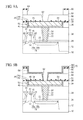
- FIGS. 18A to 22B are sectional views of the semiconductor device including interconnections of Cu, which illustrate the method for manufacturing the semiconductor device (Part 1).
- an inter-layer insulation film 102 of a low dielectric constant (low-K) insulation film is formed on a semiconductor substrate 100 with active devices (not illustrated), such as transistors, etc.
- a cap film 104 is formed (see FIG. 18A ).
- interconnection trenches 106 are formed in the cap film 104 and the inter-layer insulation film 102 (see FIG. 18B ).
- a barrier film 108 of tantalum (Ta)-based material is formed by sputtering (see FIG. 18C ).
- a barrier metal film 108 of a Ta-based material a Ta film, a tantalum nitride (TaN) film, or the layer film of a Ta film and a TaN film is formed.
- the barrier metal film 108 is for preventing the diffusion of the Cu of an interconnection 114 which will be described later into the inter-layer insulation film.
- a seed film 110 of Cu film is formed by sputtering (see FIG. 19A ).
- the seed film 110 functions as the electrode in forming a Cu film 112 by electroplating.
- a Cu film 112 is formed by electroplating.
- the interconnection trench 106 is filled with the Cu film 112 (see FIG. 19B ).
- the barrier insulation film 116 is for preventing the diffusion of the Cu of the interconnection 114 into the inter-layer insulation film.
- an inter-layer insulation film 118 of a low dielectric constant insulation film is formed.
- an inter-layer insulation film 120 of a low dielectric constant insulation film is formed.
- a cap film 122 is formed (see FIG. 20A ).
- a contact hole 124 is formed in the cap film 122 , the inter-layer insulation film 120 and the inter-layer insulation film 118 (see FIG. 20B ).
- an interconnection trench 126 is formed in the cap film 122 and the inter-layer insulation film 120 , the interconnection trench 126 being in contact with the contact hole 124 at the top of the contact hole 124 . Concurrently therewith, the barrier insulation film 116 on the interconnection 114 is removed to cause the contact hole 124 to reach the interconnection 114 (see FIG. 20C ).
- a barrier film 128 of a Ta-based material is formed by sputtering on the side surface (or the bottom surface and the side surface) of the contact hole 124 , on the bottom surface and the side surface of the interconnection trench 126 and on the cap film 122 (see FIG. 21A ).
- the barrier metal film 128 of a Ta-based material the layer film of a Ta film, a TaN film or the layer film of a Ta film and a TaN film is formed.
- the barrier metal film 128 is for preventing the diffusion of the Cu of a conductor plug 134 and an interconnection 136 which will be described later into the inter-layer insulation film.
- a seed film 130 of Cu film is formed by sputtering (see FIG. 21B ).
- the seed film 130 functions as the electrode in forming the Cu film 132 by electroplating.
- a Cu film 132 is formed on the seed film 130 by electroplating.
- the interconnection trench 126 and the contact hole 124 are filled by the Cu film 132 (see FIG. 21C ).
- the Cu film 132 and the barrier metal film 128 are polished by CMP until the surface of the cap film 122 is exposed.
- the conductor plug 134 of Cu is buried in the contact hole 124
- the interconnection 136 of Cu is buried in the interconnection trench 126 (see FIG. 22A ).
- the conductor plug 134 and the interconnection 136 are formed integral with each other.
- a barrier insulation film 138 is formed on the interconnection 136 and the cap film 122 (see FIG. 22B ).
- the barrier insulation film 138 is for preventing the diffusion of the Cu of the conductor plug 134 and the interconnection 136 into the inter-layer insulation film.
- low dielectric constant insulation film more specifically, porous low dielectric constant insulation film used as the inter-layer insulation films can be apt to absorb water when damaged with dry etching for forming the interconnection trenches and the contact holes.
- the barrier metal film of Ta-based material as described above the phenomenon that the interfaces of the barrier metal films and the interconnections of Cu are oxidized with water accumulated in the low dielectric constant insulation films takes place. Resultantly, the electro-migration resistance of the interconnections of Cu degrades.
- barrier metal films of titanium (Ti) can be used.
- the interfaces between the barrier metal films and the interconnections of Cu are not easily oxidized, etc., good electro-migration resistance can be obtained.
- heat of about 350-450° C. is applied after the Cu film to be the interconnection has been formed, the Ti of the barrier metal film is diffused into the Cu film, and the interconnection resistance rises.
- the technique of forming an interface layer containing silicon (Si) in the interface of the interconnections of Cu and the barrier insulation film can be used.
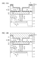
- Part 2 A method for manufacturing the semiconductor device (Part 2) will be explained with reference to FIGS. 23A and 23B .
- the semiconductor device up to the interconnection 136 of Cu buried in the interconnection trench 126 is formed (see FIG. 23A ).
- the surface of the interconnection 136 is exposed to silane gas.
- a barrier insulation film 138 is formed on the interconnection 136 and the cap film 122 (see FIG. 23B ).
- an interface layer 140 containing Si is formed on the surface of the interconnection 136 .
- an Si-content interface layer may be formed in the same way as the interface layer on the interconnection 136 , which is the second layer.
- FIGS. 24A to 24C are graphs of characteristics of the Cu interconnections for comparison.
- the Cu interconnection illustrated in FIGS. 18A to 22B with the barrier metal film of the Ta-based material formed, the Cu interconnection with the barrier metal film of Ti formed, the interconnection with the barrier metal film of a Ta-based material formed and the interface layer containing Si formed on the surface of the interconnection illustrated in FIGS. 23A and 23B were compared in the interconnection resistance.
- the three cases were compared in the electro-migration lifetime.
- FIG. 24C the three cases were compared in the stress migration defect rate.
- the electro-migration lifetime was evaluated by the electro-migration test in which current of a 2.5 MA/cm 2 current density was flowed at 250° C.
- the stress migration defect rate was evaluated by the stress migration test in which 200° C. was held for 504 hours.
- the interconnection resistance is retained low.
- the electro-migration resistance is also good.
- the stress migration resistance degrades.
- the degradation of the stress migration resistance will due to the processing of the exposure to silane gas for forming the Si-content interface layer. That is, when the surface of the interconnection of Cu is exposed to a reducing gas, such as silane gas or others, the Cu of the interconnection is more likely diffused and increase concavities and convexities in the surface of the interconnection.
- the barrier film of a Ta-based material When the barrier film of a Ta-based material is used, due to poor close contact between the Ta and the Cu, concavities and convexities especially in the interconnection surface tend to increase.
- the concavities and convexities in the thus formed interconnection surface will be sites for forming cores of voids which induce the stress migration, which will be a factor for the degradation of the stress migration resistance.
- the above-described techniques cannot retain the interconnection resistance low and/or cannot make both of the electro-migration resistance and the stress migration resistance good enough.
- the semiconductor device according to a first embodiment and the method for manufacturing the semiconductor device will be explained with reference to FIGS. 1 to 16C .
- FIG. 1 is a sectional view of the semiconductor device according to the present embodiment, which illustrates the structure thereof.
- device isolation regions 12 for defining device regions are formed on a semiconductor substrate 10 of, e.g., silicon.
- a gate electrode 16 is formed with a gate insulation film 14 formed therebetween.
- impurity diffused regions 18 a forming the shallow regions of an extension source/drain structure, i.e., the extension regions are formed.
- a sidewall insulation film 20 of silicon oxide film is formed on the side wall of the gate electrode 16 .
- impurity diffused regions 18 b forming the deep regions of the extension source/drain structure are formed.
- the shallow impurity diffused regions 18 a and the deep impurity diffused regions 18 b form the source/drain diffused layer 18 of the extension source/drain structure.
- a metal silicide film 22 of, e.g., nickel silicide is formed on the gate electrode 16 and on the source/drain diffused layer 18 .
- transistors 24 each including the gate electrode 16 and the source/drain diffused layer 18 are formed.
- an insulation film 26 of, e.g. silicon nitride film is formed on the semiconductor substrate 10 with the transistors 24 formed on.
- an insulation film 28 of, e.g., silicon oxide film is formed on the insulation film 26 .
- contact holes 30 are formed down to the source/drain diffused layer 18 .
- a barrier metal film 32 of, e.g. titanium nitride (TiN) is formed.
- a conductor plug 34 of, e.g., tungsten is buried in each contact hole 30 with the barrier metal film 32 formed in.
- an inter-layer insulation film 36 of low dielectric constant insulation film is formed on the insulation film 28 with the conductor plug 34 buried in.
- the inter-layer insulation film 36 a coating-type porous low dielectric constant insulation film is used.
- the low dielectric constant insulation film means an insulation film whose relative dielectric constant is lower than silicon oxide film, i.e., an insulation film whose relative dielectric constant is smaller than 4.
- a cap film 38 of, e.g., SiN film or SiC film is formed on the inter-layer insulation film 36 .
- the film thickness of the cap film 38 is, e.g., about 10-100 nm.
- interconnection trenches 40 connected to the conductor plugs 34 are formed.
- each interconnection trench 40 i.e., on the side surface and the bottom surface of the interconnection trench 40 , a Ti film 42 is formed.
- the film thickness of the Ti film 42 on the side surface and the bottoms surface of the interconnection trench 40 is, e.g., about 0.5-10 nm.
- a Ta film 44 is formed on the Ti film 42 in the interconnection trench 40 .
- the film thickness of the Ta film on the side surface and the bottom surface of the interconnection trench 40 is, e.g., about 3-20 nm.
- a barrier metal film 46 of the layer film of the Ti film 42 and the Ta film 44 is formed on the side surfaces and the bottom surfaces of the interconnection trenches 40 .
- the barrier metal film 46 is for preventing the diffusion of the Cu of an interconnection 50 to be described layer into the inter-layer insulation film.
- a Cu film 48 is buried.
- interconnections 50 of Cu are buried.
- the interconnections 50 are connected to the conductor plugs 34 .
- a barrier insulation film 52 of, e.g., SiCN film or SiCO film is formed on the interconnections 50 and the cap film 38 .
- the film thickness of the barrier insulation film 52 is, e.g., about 10-100 nm.
- the barrier insulation film 52 is for preventing the diffusion of the Cu of the interconnections 50 into the inter-layer insulation film.
- an interface layer 54 containing Ti and Si is formed in the interface between the interconnection 50 and the barrier insulation film 52 , i.e., on the surface of the interconnection 50 .
- the Ti contained in the interface layer 54 is supplied by diffusing the Ti of the Ti film 42 of the barrier metal film 46 into the surface of the interconnection 50 by heat processing to deposit.
- the Si contained in the interface layer 54 is supplied by exposing the surface of the interconnection 50 to a silicon content gas, as will be described later.
- the interface layer 54 may be formed in a continuous film or in islets separated from each other.
- the interface layer, i.e., the layer containing Ti and Si is not limited to the layer formed in a continuous film and can be the layer formed in islets separated from each other.
- an inter-layer insulation film 56 of low dielectric constant insulation film is formed on the barrier insulation film 52 .
- the inter-layer insulation film 56 the low dielectric constant insulation film of, e.g., SiOC film is used.
- an inter-layer insulation film 58 of low dielectric constant insulation film is formed on the inter-layer insulation film 56 .
- an inter-layer insulation film 58 of low dielectric constant insulation film is formed.
- a coating-type porous low dielectric constant insulation film for example, is used.
- a cap film 60 of, e.g., SiN film or SiC film is formed on the inter-layer insulation film 58 .
- the film thickness of the cap film 60 is, e.g., about 10-100 nm.
- contact holes 62 are formed down to the interconnections 50 .
- interconnection trenches 64 are formed, connected to the tops of the contact holes 62 .
- a Ti film 66 is formed in the contact holes 62 and in the interconnection trenches 64 , i.e., on the side surfaces of the contact holes 62 and on the side surfaces and the bottom surfaces of the interconnection trenches 64 .
- the film thickness of the Ti film 66 on the side surfaces and the bottom surfaces of the interconnection trenches 64 is, e.g., about 0.5-10 nm.
- a Ta film 68 is formed on the Ti film 66 in the contact holes 62 and the interconnection trenches 64 .
- the film thickness of the Ta film 68 on the side surfaces and the bottom surfaces of the interconnection trenches 64 is, e.g., about 3-20 nm.
- a barrier film 70 of the layer film of the Ti film 66 and the Ta film 68 is formed on the side surfaces of the contact holes 62 and on the side surfaces and the bottom surfaces of the interconnection trenches 64 .
- the barrier metal film 70 is for preventing the diffusion of the Cu of conductor plugs 74 and interconnections 76 which will be described later into the inter-layer insulation films.
- the barrier metal film 70 is not formed on the bottoms of the contact holes 62 .
- the interconnections 50 and the conductor plugs 74 can have good contact.
- the conductor plugs 74 of Cu are buried in the contact holes 62
- the interconnections 76 of Cu are buried in the interconnection trenches 64 .
- the conductor plugs 74 and the interconnections 76 are formed integral with each other.
- the interconnections 76 are electrically connected to the interconnections via the conductor plugs 74 .
- a barrier insulation film 78 of, e.g., SiCN film or SiCO film is formed on the interconnections 76 and the cap film 60 .
- the barrier insulation film 78 is for preventing the diffusion of the Cu of the conductor plugs and the interconnections 76 into the inter-layer insulation film.
- a interface layer 80 containing Ti and Si is formed in the interfaces between the interconnections 76 and the barrier insulation film 78 , i.e., on the surfaces of the interconnections 76 .
- the Ti contained in the interface layer 80 is supplied by diffusing the Ti of the Ti film 66 of the barrier metal film 70 into the surfaces of the interconnections 76 by thermal processing to deposit.
- the Si contained in the interface layer 80 is supplied by exposing the surfaces of the interconnections 76 to a silicon-content gas.
- the interface layer 80 may be formed in a continuous film or in islets separated from each other.
- the semiconductor device according to the present embodiment including the interconnections 50 , 76 of Cu is constituted.
- the semiconductor device includes the barrier metal films 46 , 70 of the layer film of Ti film and Ta film, and the interface layers 54 , 80 containing Ti and Si are formed on the surface of the interconnections 50 , 78 of Cu.
- the interface layers 54 , 80 containing Ti and Si, which are formed on the surfaces of the interconnections 50 , 76 can improve the adhesion between the interconnections 50 , 76 and the barrier insulation films 52 , 78 .
- the barrier metal films 46 , 70 formed of the layer film of Ti film and Ta film the concentration of the Ti diffused in the interconnections 50 , 76 of Cu can be suppressed low.
- the interconnection resistance of the interconnections 50 , 76 of Cu can be retained low, and the stress migration resistance can be largely improved without degrading the electro-migration resistance.
- FIGS. 2A to 11B are sectional views of the semiconductor device according to the present embodiment in the steps of the method for manufacturing the semiconductor device, which illustrate the method.
- the semiconductor substrate 10 of, e.g., silicon N-type wells and P-type wells (either not illustrated) are suitably formed.
- a ( 100 ) P-type silicon substrate is used as the semiconductor substrate 10 .
- the device isolation regions 12 for defining the device regions are formed by, e.g., STI (Shallow Trench Isolation).
- STI Shallow Trench Isolation
- the trenches for the device isolation are formed in the semiconductor substrate 10 by dry etching.
- the trenches are filled with insulation film by CVD (Chemical Vapor Deposition).
- the buried insulation film in the trenches is planarized by CMP to form the device isolation regions 12 of insulation film.
- a dopant impurity for the channels is implanted into the semiconductor substrate 10 , and then thermal processing for activating the implanted dopant impurity is made.
- the gate insulation film 14 is formed on the entire surface by, e.g., CVD.
- a polysilicon film 16 is formed on the entire surface by, e.g., CVD. Then, a dopant impurity is implanted into the polysilicon film 16 by, e.g., ion implantation.
- the polysilicon film 16 is patterned to form the gate electrodes 16 of the polysilicon film (see FIG. 2A ).
- a dopant impurity is implanted into the semiconductor substrate 10 on both sides of the gate electrode 16 with the gate electrode 16 as the mask.
- the impurity diffused regions 18 a forming the shallow regions of the extension source/drain structure, i.e., the extension regions (see FIG. 2B ).
- a silicon oxide film 20 is formed on the entire surface by, e.g., CVD and the silicon oxide film 20 is anisotropically etched by dry etching.
- the sidewall insulation film 20 of the silicon oxide film is formed on the sidewalls of the gate electrodes 16 (see FIG. 2C ).
- a dopant impurity is implanted into the semiconductor substrate 10 with the gate electrodes 16 and the sidewall insulation film 20 as a mask.
- the impurity diffused regions 18 b forming the deep regions of the extension source/drain structure are formed.
- the shallow impurity diffused regions 18 a and the deep impurity diffused regions 18 b form the source/drain diffused layer 18 of the extension source/drain structure (see FIG. 3A ).
- thermal processing for activating the dopant impurities implanted into the gate electrodes 16 and the source/drain diffused layer 18 .
- the transistors 24 including the gate electrode 16 and the source/drain diffused layer 18 are formed.
- Ni nickel (Ni) film (not illustrated) containing platinum (Pt) is formed by, e.g., PVD (Physical Vapor Deposition).
- PVD Physical Vapor Deposition
- a cap film (not illustrated) of TiN film is formed on the entire surface by, e.g., PVD.
- thermal processing is made by, e.g., RTA (Rapid Thermal Annealing).
- the Ni film on the cap film and the insulation film, which has not reacted is selectively removed.
- thermal processing is made by, e.g., RTA.
- the metal silicide film 22 of nickel silicide film is formed on the tops of the gate electrodes 16 and the tops of the source/drain diffused layers 18 (see FIG. 2B ).
- the insulation film 26 of silicon nitride film is formed by, e.g., plasma CVD.
- the insulation film 28 of silicon oxide film is formed by, e.g., plasma CVD.
- the insulation film 28 is polished by, e.g., CMP, and the insulation film 28 is planarized (see FIG. 3C ).
- the contact holes 30 are formed in the insulation films 28 , 26 down to the source/drain diffused layer 18 (see FIG. 4A ).
- the barrier metal film 32 of, e.g., TiN film is formed by, e.g., PVD.
- a tungsten film 34 is formed by, e.g., CVD.
- the tungsten film 34 and the barrier metal film 32 are polished until the surface of the insulation film 28 is exposed.
- the conductor plugs 34 of the tungsten film are buried in the contact holes 30 (see FIG. 4B ).
- the inter-layer insulation film of low dielectric constant insulation film is formed on the insulation film 28 with the conductor plugs 34 buried in.
- the inter-layer insulation film 36 a coating-type porous low dielectric constant insulation film is formed.
- the cap film 38 of SiN film or SiC film is formed by, e.g., CVD (see FIG. 4C ).
- the film thickness of the cap film 38 is, e.g., about 10-100 nm.
- the interconnection trenches 40 are formed in the cap film 38 and the inter-layer insulation film 36 , connected to the conductor plugs 34 (see FIG. 5A ).
- a Ti film 42 is formed by, e.g., long-throw sputtering.
- the film thickness of the Ti film 42 is, e.g., about 0.5-10 nm.
- the conditions for forming the Ti film 42 are as exemplified below.
- the target electric power is, e.g., 0.5-18 kW.
- the substrate bias is, e.g., 0-500 W. Under these conditions, the Ti film 42 is formed so the Ti film 42 on the cap film 38 can have a 10 nm-film thickness. At this time, the film thickness of the Ti film 42 on the side surfaces and the bottom surfaces of the interconnection trenches 40 becomes about 1.0 nm.
- the Ti film 42 is formed on the side surfaces and the bottom surfaces of the interconnection trenches 40 having parts whose film thickness is at least 0.5 nm or above.
- a Ta film 44 is formed by, e.g., long-throw sputtering.
- the film thickness of the Ta film 44 is about, e.g., 3-20 nm.
- the conditions for forming the Ta film 44 are as exemplified below.
- the target electric power is, e.g., 1-18 kW.
- the substrate bias is, e.g., 0 W.
- the Ta film 44 may be formed by two-steps sputtering in the same way as a Ta film 68 to be described later is formed.
- the barrier metal film 46 of the layer film of a Ti film 42 and a Ta film 44 is formed (see FIG. 5B ).
- the seed film 47 of Cu film is formed by, e.g., sputtering (see FIG. 6A ).
- the film thickness of the seed film 47 is, e.g., about 10-300 nm.
- the seed film 47 functions as the electrode in forming the Cu film 48 by electroplating.
- the Cu film 48 is formed on the entire surface by electroplating.
- the thickness of the Cu film is, e.g., about 100-1500 nm.
- the interconnection trenches 40 are filled with the Cu film (see FIG. 6B ).
- the Cu film 48 and the barrier metal film 46 are polished until the surface of the cap film 38 is exposed to planarized the Cu film 48 .
- the interconnections 50 of Cu are buried in the interconnection trenches 40 (see FIG. 7A ).
- thermal processing is made to diffuse the Ti of the Ti film 42 into the surface of the interconnections 50 to deposit.
- the thermal processing temperature is, e.g., about 256-450° C.
- the thermal processing period of time is, e.g., about 1 second to 30 minutes, specifically about 10 seconds.
- This thermal processing may be made, e.g., in vacuum, or hydrogen gas, ammonium gas, argon gas, helium gas, nitrogen gas or a mixed gas of these gases.
- the thermal processing may be made while plasma processing is being made on the surfaces of the interconnections 50 and the cap film 38 .
- the plasma processing may be made before or after the thermal processing.
- the plasma processing uses a plasma atmosphere generated by using, e.g., hydrogen gas, ammonium gas, argon gas, helium gas, nitrogen gas or a mixed gas of these gases.
- the diffusion of the Ti into the surfaces of the interconnections 50 and the deposition can be advanced also by heat applied in later steps, and the thermal processing for diffusing the Ti of the Ti film 42 into the surfaces of the interconnections 50 to deposit may not be made essentially independently.
- silylation processing for exposing the surfaces of the interconnections 50 to a silicon-content gas is made.
- the processing conditions for the silylation processing are as exemplified below.
- the silicon-content gas is silane (SiH 4 ) gas.
- the processing temperature is about 256-450° C.
- the processing pressure is about 0.1-10 Torr.
- the processing period of time is about 1 second to 3 minutes.
- plasma processing may be made to the surfaces of the interconnections 50 and the cap film 38 .
- a plasma atmosphere generated by using, hydrogen gas, ammonium gas, argon gas, helium gas, nitrogen gas or a mixed gas of there gases is used.
- the barrier insulation film 52 of, e.g., SiCN film or SiCO film is formed by, e.g., CVD (see FIG. 7B ).
- the film thickness of the barrier insulation film 52 is, e.g., about 5-100 nm.
- the barrier insulation film 52 is formed, e.g., in one and the same reaction chamber continuously without opening the reaction chamber.
- the thermal processing for diffusing the Ti of the Ti film 42 into the surfaces of the interconnections 50 to deposit is made, and the silylation processing for exposing the surfaces of the interconnections 50 to a silicon-content gas is made.
- the interface layer 54 containing Ti and Si is formed in the interfaces between the interconnections 50 and the barrier insulation film 52 , i.e., the surfaces of the interconnections 50 (see FIG. 7B ).
- the inter-layer insulation film 56 of low dielectric constant insulation film is formed.
- the low dielectric constant insulation film of, e.g., SiOC film is formed.
- the inter-layer insulation film 58 of low dielectric constant insulation film is formed on the inter-layer insulation film 56 .
- the inter-layer insulation film 58 a coating-type porous low dielectric constant insulation film, for example, is formed.
- the cap film 60 of, e.g., SiN film or SiC film is formed (see FIG. 8A ).
- the film thickness of the cap film 60 is, e.g., about 10-100 nm.
- the contact holes 62 are formed in the cap film 60 , the inter-layer insulation film 58 and the inter-layer insulation film 56 (see FIG. 8B ).
- the interconnection trenches 64 connected to the tops of the contact holes 62 are formed, and simultaneously therewith, the barrier insulation film 52 on the interconnections 50 is removed to arrive the contact holes 62 at the interconnections 50 (see FIG. 9A ).
- the interface layer 54 at the bottoms of the contact holes 62 is removed in the step in which the deposition and the etching of Ta simultaneously advance, which will be described later.
- a Ti film 66 is formed by, e.g., long-throw sputtering.
- the film thickness of the Ti film 66 is, e.g., about 0.5-10 nm.
- the conditions for forming the Ti film 66 are as exemplified below.
- the target electric power is, e.g., 0.5-18 kW.
- the substrate bias is, e.g., 0-500 W. Under these conditions, the Ti film 66 is formed so that Ti film 66 on the cap film 60 is 10 nm.
- the film thickness of the Ti film 66 on the side surfaces or the bottom surfaces of the contact holes 62 or on the side surfaces or the bottom surfaces of the interconnection trenches 64 is about 1.0 nm.
- the Ti film 66 is formed on the side surfaces or the bottom surfaces of the contact holes 62 , or the side surfaces or the bottom surfaces of the interconnection trenches 64 so they can have parts whose film thickness is at least 0.5 nm or above.
- a Ta film 68 is formed by, e.g., long-throw sputtering.
- the thickness of the Ta film 68 is, e.g., about 3-20 nm.
- the Ta film 68 is formed by the sputtering of two-steps of the step using the film forming conditions for advancing the deposition alone of the Ta, and the following step using the film forming conditions for simultaneously advancing the deposition and etching of the Ta, as exemplified below.
- the Ta film 68 of a 5-10 nm-thickness is deposited under the film forming conditions of, e.g., 1-18 kW target power and 0 W substrate bias.
- the film forming conditions of, e.g., 1-18 kW target power and 0-500 W substrate bias are used so the deposition rate Vd and the etching rate Ve on the cap film 60 , i.e., the flat parts can be respectively 0.7 nm/s and 0.9 nm/s.
- the Vd/Ve ratio is smaller at the bottoms of the interconnection trenches 64 or the contact holes 62 than on the cap film 60 , i.e., at the flat parts.
- the Ti film 66 at the bottoms of the interconnection trenches 64 or the contact holes 62 is etched and attaches again to the side surfaces of the interconnection trenches 64 or the contact holes 62 .
- the mixed layer of the Ti and Ta is formed on the surfaces of the Ta film 68 formed on the side surfaces of the interconnection trenches 64 or the contact holes 62 . This improves the efficiency of diffusing and deposit the Ti on the surfaces of the interconnections 76 .
- the Ti film 66 on the bottoms of the contact holes 62 is etched off, or the Ta film 68 is not substantially formed on the bottoms of the contact holes 62 . This makes good contacts of the interconnections 50 and the conductor plugs 74 .
- the barrier metal film 70 of the layer film of the Ti film 66 and the Ta film 68 is formed (see FIG. 9B ).
- the seed film 71 of Cu film is formed by, e.g., sputtering (see FIG. 10A ).
- the film thickness of the seed film 71 is, e.g., about 10-300 nm.
- the seed film 71 functions as the electrode in forming a Cu film 72 by electroplating.
- the Cu film 72 is formed by electroplating.
- the thickness of the Cu film 72 is, e.g., about 100-1500 nm.
- the contact holes 62 and the interconnection trenches 64 are filled with the Cu film 72 (see FIG. 10B ).
- the Cu film 72 and the barrier metal film 70 are polished by CMP until the surface of the cap film 60 is exposed to planarize the Cu film 72 .
- the conductor plugs 74 of Cu are buried in the contact holes 62 and the interconnections 76 of Cu are buried in the interconnection trenches 64 (see FIG. 11A ).
- the conductor plugs 74 and the interconnections 76 are formed integral with each other.
- thermal processing is made to diffuse the Ti of the Ti film 66 into the surface of the interconnections 76 to deposit.
- the thermal processing temperature is, e.g., about 256-450° C.
- the thermal processing period of time is, e.g., 1 second to 30 minutes, specifically about 10 seconds.
- This thermal processing may be made in vacuum, or in hydrogen gas, ammonium gas, argon gas, helium gas, nitrogen gas or a mixed gas of these gases.
- the thermal processing may be made while plasma processing is made on the surfaces of the interconnections 76 and the cap film 60 .
- the plasma processing may be made before or after the thermal processing.
- a plasma atmosphere generated by using hydrogen gas, ammonium gas, argon gas, helium gas, nitrogen gas or a mixed gas of these gases is used.
- the diffusion and the deposition of the Ti on the surfaces of the interconnections 76 can be advanced by heat which will be applied in later steps.
- the thermal processing for diffusing the Ti of the Ti film 66 into the surfaces of the interconnections 76 to deposit may not be made essentially independently.
- silylation processing for exposing the surfaces of the interconnections 76 to silicon-content gas is made.
- the processing conditions for the silylation processing are as exemplified below.
- the silicon-content gas SiH 4 gas is used.
- the processing temperature is about 256-450° C.
- the processing pressure is about 0.1-10 Torr.
- the processing period of time is about 1 second to 3 minutes.
- plasma processing may be made on the surfaces of the interconnections 76 and the cap film 60 .
- a plasma atmosphere generated by using, e.g., hydrogen gas, ammonium gas, argon gas, helium gas, nitrogen gas or a mixed gas of these gases.
- the barrier insulation film 78 of, e.g., SiCN film or SiCO film is formed by, e.g., CVD (see FIG. 11B ).
- the film thickness of the barrier insulation film 78 is, e.g., about 5-100 nm.
- the barrier insulation film 78 is formed in one and the same reaction chamber continuously without opening the reaction chamber.
- the interface layer 80 containing Ti and Si is formed in the interface between the interconnections 76 and the barrier insulation film 78 , i.e., the surfaces of the interconnections 76 (see FIG. 11B ).
- interconnections 76 are formed, interconnections not illustrated are further formed.
- the semiconductor device according to the present embodiment illustrated in FIG. 1 is manufactured.
- the layer film of Ti film and Ta film is formed as the barrier metal films 46 , 70 . Furthermore, in the present embodiment, before the barrier insulation films 52 , 78 are formed, the thermal processing for diffusing the Ti of the Ti films 42 , 66 of the barrier metal films 46 , 70 into the surfaces of the interconnections 50 , 76 to deposit is made, and the silylation processing for exposing the surfaces of the interconnections 50 , 76 to silicon-content gas is made. Thus, the interface layers 54 , 80 containing Ti and Si are formed on the surfaces of the interconnections 50 , 76 .
- the interface layers 54 , 80 containing Ti and Si formed on the surfaces of the interconnections 50 , 76 because of the interface layers 54 , 80 containing Ti and Si formed on the surfaces of the interconnections 50 , 76 , the adhesion between the interconnections 50 , 76 and the barrier insulation film 52 , 78 can be improved. Thus, the degradation of the stress migration resistance can be drastically improved without degrading the electro-migration resistance. Because of the layer film of Ti film and Ta film as the barrier metal films 46 , 70 , the concentration of the Ti diffused in the interconnections 50 , 76 of Cu can be suppressed low. Accordingly, the interconnection resistance can be retained low.
- the interconnection resistance can be retained low, and besides, the stress migration resistance can be drastically improved without degrading the electro-migration resistance.
- FIGS. 12 and 13 are graphs of the results of the depth-wise compositions of the samples subjected to the thermal processing and the silylation processing which have been analyzed by SIMS (Secondary Ion Mass Spectroscopy).
- FIG. 14 is a graph of the relationships between the Ti intensity and the thermal processing temperature of the interface between the Cu film and the barrier insulation film.
- 15 is a graph of the result of measuring by XPS (X-ray Photoelectron Spectroscopy) the Si intensity of the surfaces of the Cu films of samples having the surface of the Cu films exposed to SiH 4 gas and samples having the surfaces of the Cu films exposed to 4MS gas.
- XPS X-ray Photoelectron Spectroscopy
- the samples analyzed by SIMS were prepared as follows. A 15 nm-thickness Ti film, a 3 nm-thickness Ta film, a 60 nm-thickness Cu film and a 30 nm-thickness barrier insulation film were sequentially laid on a silicon substrate with silicon oxide film formed therebetween. Before the barrier insulation film was formed, the thermal processing for diffusing the Ti into the surface of the Cu film to deposit, and the silylation processing for exposing the surface of the Cu film to silane gas were made. The samples were of 2 kinds one of which was prepared with the temperature of the thermal processing for diffusing and depositing the Ti set at 274° C. and the other of which was prepared with the temperature of the thermal processing for diffusing and deposit the Ti set at 368° C.
- FIG. 12 is a graph of the result of analyzing by SIMS the depth-wise composition of the sample prepared with the thermal processing temperature set at 274° C.
- FIG. 13 is a graph of the result of analyzing by SIMS the depth-wise composition of the sample prepared with the thermal processing temperature set at 368° C.
- the application period of time of primary ions corresponding to depths of the samples, and the intensities of the detected secondary ions are taken on the vertical axis.
- the Ti concentration of the Cu film except the vicinity to the interface with the barrier insulation film is suppressed low.
- the Ti concentration of the Cu film is suppressed thus low, whereby the interconnection resistance will be suppressed low.
- FIG. 12 and FIG. 13 are compared to each other, it is found that the Ti concentration of the interface between the Cu film and the barrier insulation film of the sample having the thermal processing temperature set at 368° C. is higher than that of the sample having the thermal processing temperature set at 274° C.
- FIG. 14 is a graph of the Ti intensities of the interface between the Cu film and the barrier insulation film, which has been given by the result of the above analysis by SIMS plotted with respect to the thermal processing temperatures, i.e., the substrate temperatures.
- the temperature of the thermal processing for diffusing the Ti into the surfaces of the interconnections of Cu and deposit is set at 256° C. or above.
- the temperature of the thermal processing for diffusing the Ti into the surfaces of the interconnections of Cu to deposit is set at 450° C. or below.
- the temperature of the silylation processing for exposing the surfaces of the interconnections of Cu to silicon-content gas is set at 256° C. or above and 450° C. or below.
- the silylation processing for exposing the surfaces of the interconnections of Cu is made before the barrier insulation film is formed. Thereafter also in forming the barrier insulation film, the surfaces of the interconnections are exposed also to tetramethyl silane (4MS) gas used as the raw material gas. However, by only the exposure to 4MS gas, substantially no Si is deposited on the surfaces of the interconnections as will be described below.
- 4MS tetramethyl silane
- FIG. 15 compares the intensities of the Si-2p peak measured by XPS on the sample with the surface of the Cu film exposed to SiH 4 gas and the sample with the surface of the Cu film exposed to 4MS gas.
- 4 MS gas used as the raw material gas of the barrier insulation film cannot supply Si sufficient to form the interface layer containing Ti and Si.
- FIG. 16 is graphs of the result of evaluating the method for manufacturing the semiconductor device according to the present embodiment.
- FIG. 16A the sample of an example and the sample of a control are compared in the interconnection resistance.
- FIG. 16B the electro-migration life is compared between both samples.
- FIG. 16C the stress migration defect rate is compared between both samples.
- the sample of the example is the interconnection formed by the method for manufacturing the semiconductor according to the present embodiment.
- the sample of the control is the interconnection using a barrier metal film of a Ta-based material and having no interface layer, i.e., the interconnection formed by the method for manufacturing the semiconductor device illustrated in FIGS. 18A to 22B .
- the electro-migration life was evaluated by the electro-migration test in which current of a 2.5 MA/cm 2 current density was flowed at 250° C.
- the stress migration defect rate was evaluated by the stress migration test in which the samples were retained for 504 hours at 200° C.
- the interconnection resistance is retained low, as in the sample of the control.
- the electro-migration resistance is much improved in comparison with that of the sample of the control.
- the electro-migration life of the sample of the example is 10 times or above the electro-migration life of the sample of the control.
- the stress migration defect rate is retained low, and the stress migration resistance is good, as in the sample of the control. It will be for the following reason that the stress migration resistance of the sample of the example is not degraded. That is, in the sample of the example having the barrier metal film of the layer film of a Ti film and a Ta film and the interface layer containing Ti and Si, the adhesion between the Ta film on the Ti film, and the Cu film is so good that concavities and convexities in the surfaces of the interconnections which are one factor for the degradation of the stress migration resistance can be made small. Thus, in the sample of the example, the degradation of the stress migration resistance will be prevented.
- the interconnections of Cu retain the interconnection resistance low and besides can much improve the electro-migration resistance without degrading the stress migration resistance.
- FIG. 17 is a sectional view of the semiconductor device according to the present embodiment.
- the same members of the present embodiment as those of the semiconductor device according to the first embodiment and the method for manufacturing the semiconductor device are represented by the same reference numbers not to repeat or to simplify their explanation.
- the semiconductor device according to the present embodiment is characterized mainly in that barrier metal films 86 , 88 of the layer film of a Ti film and a Ta film are used in place of the barrier metal films 46 , 70 of the layer film of a Ti film and a Ta film.
- a Ti film 82 is formed in interconnection trenches 40 , i.e., on the side surfaces and the bottom surfaces of the interconnection trenches 40 .
- a TaN film 84 is formed on the Ti film 82 in the interconnection trenches 40 .
- the barrier metal film 86 of the layer film of the Ti film 82 and the TaN film 84 is formed on the side surfaces and the bottom surfaces of the interconnection trenches 40 .
- the barrier metal film 86 is for preventing the diffusion of the Cu of the interconnections 50 into the inter-layer insulation film. It is possible that a TiN film is formed between the Ti film 82 and the TaN film 84 to thereby form the barrier metal film 86 of the layer film of the Ti film 82 , the TiN film and the TaN film 84 .
- the interconnections 50 of Cu are buried.
- a barrier insulation film 52 is formed on the interconnections 50 and the cap film 38 .
- an interface layer 54 containing Ti and Si is formed in the interface between the interconnections 50 and the barrier insulation film 52 , i.e., on the surfaces of the interconnections 50 .
- the Ti contained in the interface layer 54 has been supplied by diffusing, by thermal processing, the Ti of the Ti film 82 of the barrier metal film 86 into the surfaces of the interconnections 50 to deposit.
- the Si contained in the interface layer 54 has been supplied by exposing the surfaces of the interconnections 50 to a silicon-content gas.
- a Ti film 88 is formed in the contact holes 62 and in the interconnection trenches 64 , i.e., on the side surfaces of the contact holes 62 and on the side surfaces and the bottom surfaces of the interconnection trenches 64 .
- a TaN film 90 is formed on the Ti film 88 in the contact holes 62 and in the interconnection trenches 64 .
- a barrier metal film 92 of the layer film of the Ti film 88 and the TaN film 90 is formed on the side surfaces of the contact holes 62 and on the side surfaces and the bottom surfaces of the interconnection trenches 64 . It is possible that a TiN film is formed between the TiN film 88 and the TaN film 90 to form the barrier metal film 92 of the layer film of the Ti film 88 , the TiN film and the TaN film 90 .
- a Cu film 72 is buried in the contact holes 62 and the interconnection trenches 64 with the barrier metal film 92 formed in.
- conductor plugs 74 of Cu are buried in the contact holes 62
- interconnections 76 of Cu are buried in the interconnection trenches 64 .
- a barrier insulation film 78 is formed on the interconnections 76 and the cap film 60 .
- an interface layer 80 containing Ti and Si is formed in the interfaces between the interconnections 76 and the barrier film 78 , i.e., on the surfaces of the interconnections 76 .
- the Ti contained in the interface layer 80 has been supplied by diffusing, by thermal processing, the Ti of the Ti film 88 of the barrier metal film 92 into the surfaces of the interconnections 76 to deposit.
- the Si contained in the interface layer 80 has been supplied by exposing the surfaces of the interconnections 76 to a silicon-content gas.
- the barrier metal films 86 , 92 of the layer film of Ti film and TaN film may be used. Also in this case, as in the first embodiment, thermal processing for diffusing the Ti of the Ti films 82 , 88 into the surfaces of the interconnections 50 , 76 to deposit, and the silylation processing for exposing the surfaces of the interconnections 50 , 76 to a silicon-content gas are made to thereby form the interface layers 54 , 80 containing Ti and Si on the surfaces of the interconnections 50 , 76 .
- the barrier metal films 86 , 92 of the layer film of a Ti film and a TaN film are used to form the interface layers 54 , 80 containing Ti and Si, whereby the interconnection resistance can be also retained low, and besides the electro-migration resistance can be also improved without degrading the stress migration resistance.
- the Ti films 42 , 66 forming the barrier metal films 46 are formed by sputtering but may not be formed essentially by sputtering.
- the Ti films may be formed by PVD, CVD or ALD (Atomic Layer Deposition). These film deposition methods may be suitably combined.
- the Ta films 44 , 68 forming the barrier metal films 46 , 70 are formed by sputtering but may not be formed essentially by sputtering.
- the Ta films may be formed by PVD, CVD or ALD. These film deposition methods may be suitably combined.
- the Cu films 48 , forming the interconnections 50 , 76 are formed by electroplating but may not be formed essentially by electroplating.
- the Cu film may be formed by PVD, CVD or ALD. These film deposition methods may be suitable combined.
- the silicon-content gas for exposing the surfaces of the interconnections 50 , 76 of Cu SiH 4 gas is used, but the silicon-content gas is not limited to SiH 4 gas.
- the silicon-content gas for exposing the surfaces of the interconnections in place of SiH 4 gas, polysilane gas or organic silane gas may be used. A mixed gas containing at least two of these gases may be used.
- organic silane gas can be used a gas of, e.g., trimethylsilane (3MS), trimethylsilylacetylene (TMSA), dimethylsilane (2MS), tetramethoxysilane (TMOS), dimethyldimethoxysilane (DMDMOS), tetramethylcyclotetrasiloxane (TMCTS), octamethylcyclotetrasiloxane (OMCTS), dimethyldiethoxysilane (DMDEOS), dimethylphenylsilane (DMPS), diphenyldimethoxysilane (DPDMOS), diphenyldiethoxysilane (DPDEOS), phenyldiethoxysilane (PDEOS), diethoxymethylsilane (DEMS) or others.
- 3MS trimethylsilane
- TMSA trimethylsilylacetylene
- TMOS tetramethoxysilane
- DMDMOS dimethyldimethoxysilane
- the barrier metal films 46 , 70 are formed of the layer film of a Ti film and a Ta film
- the barrier metal films 86 , 92 are formed of the layer film of a Ti film and a TaN film.
- the metal films forming the barrier metal films are not limited to then.
- the lower films of the layer films forming the barrier metal films can be the metal film of Ti, nickel (Ni), cobalt (Co), zirconium (Zr), chrome (Cr), palladium (Pd), manganese (Mn), silver (Ag), aluminum (Al), tin (Sn) or others, or an alloy film containing at least two kinds of these metals. Films of the nitrides of these metals can be used.
- the upper films of the layer films forming the barrier metal film can be metal film of Ta, rhenium (Re), tungsten (W), platinum (Pt), vanadium (V), ruthenium (Ru), gold (Au) or others, or an alloy film containing at least two kinds of these metals. Films of the nitrides of these metals can be used.
- the barrier metal film 70 is not formed on the bottom surfaces of the contact holes 62 .
- the barrier metal film 70 may be formed on the bottom surfaces of the contact holes 62 .
- the interface layers 54 , 80 containing Ti and Si are formed respectively on the surfaces of the interconnections 50 , 70 .
- the interface layer containing Ti and Si may be formed on the surfaces of either of the interconnections 50 and the interconnections 70 .
- the inter-layer insulation film 36 of a single layer of low dielectric constant insulation film is formed as the inter-layer insulation film with the interconnections 50 buried in.
- an inter-layer insulation film of a plurality of low dielectric constant insulation films may be formed.
- the inter-layer insulation films 56 , 58 of 2 layers of low dielectric constant insulation film are formed, but an inter-layer insulation film of a single, or a 3 or more layers of low dielectric constant insulation film may be formed.
- inter-layer insulation films are formed of the coating-type porous film or the low dielectric constant insulation film of SiOC film.
- the inter-layer insulation films are not limited to them.
- the present invention is applied to cases where interconnections of Cu are formed.
- the present invention is applicable widely to cases where conductors containing Cu are formed.
Landscapes
- Internal Circuitry In Semiconductor Integrated Circuit Devices (AREA)
- Physics & Mathematics (AREA)
- Engineering & Computer Science (AREA)
- Plasma & Fusion (AREA)
Abstract
Description
Claims (7)
Priority Applications (1)
| Application Number | Priority Date | Filing Date | Title |
|---|---|---|---|
| US14/160,951 US9123728B2 (en) | 2008-05-12 | 2014-01-22 | Semiconductor device and method for manufacturing semiconductor device |
Applications Claiming Priority (4)
| Application Number | Priority Date | Filing Date | Title |
|---|---|---|---|
| JP2008-124583 | 2008-05-12 | ||
| JP2008124583A JP5380901B2 (en) | 2008-05-12 | 2008-05-12 | Semiconductor device and manufacturing method thereof |
| US12/366,020 US8669177B2 (en) | 2008-05-12 | 2009-02-05 | Semiconductor device and method for manufacturing semiconductor device |
| US14/160,951 US9123728B2 (en) | 2008-05-12 | 2014-01-22 | Semiconductor device and method for manufacturing semiconductor device |
Related Parent Applications (1)
| Application Number | Title | Priority Date | Filing Date |
|---|---|---|---|
| US12/366,020 Division US8669177B2 (en) | 2008-05-12 | 2009-02-05 | Semiconductor device and method for manufacturing semiconductor device |
Publications (2)
| Publication Number | Publication Date |
|---|---|
| US20140131873A1 US20140131873A1 (en) | 2014-05-15 |
| US9123728B2 true US9123728B2 (en) | 2015-09-01 |
Family
ID=41266208
Family Applications (2)
| Application Number | Title | Priority Date | Filing Date |
|---|---|---|---|
| US12/366,020 Active 2029-05-22 US8669177B2 (en) | 2008-05-12 | 2009-02-05 | Semiconductor device and method for manufacturing semiconductor device |
| US14/160,951 Active US9123728B2 (en) | 2008-05-12 | 2014-01-22 | Semiconductor device and method for manufacturing semiconductor device |
Family Applications Before (1)
| Application Number | Title | Priority Date | Filing Date |
|---|---|---|---|
| US12/366,020 Active 2029-05-22 US8669177B2 (en) | 2008-05-12 | 2009-02-05 | Semiconductor device and method for manufacturing semiconductor device |
Country Status (2)
| Country | Link |
|---|---|
| US (2) | US8669177B2 (en) |
| JP (1) | JP5380901B2 (en) |
Families Citing this family (10)
| Publication number | Priority date | Publication date | Assignee | Title |
|---|---|---|---|---|
| US8461683B2 (en) * | 2011-04-01 | 2013-06-11 | Intel Corporation | Self-forming, self-aligned barriers for back-end interconnects and methods of making same |
| CN102332425A (en) * | 2011-09-23 | 2012-01-25 | 复旦大学 | Method for enhancing electromigration resistance property in copper interconnection technology |
| US20150380296A1 (en) * | 2014-06-25 | 2015-12-31 | Lam Research Corporation | Cleaning of carbon-based contaminants in metal interconnects for interconnect capping applications |
| JP2016111104A (en) * | 2014-12-03 | 2016-06-20 | 株式会社Joled | Method of manufacturing thin-film semiconductor substrate |
| US20160276156A1 (en) * | 2015-03-16 | 2016-09-22 | Taiwan Semiconductor Manufacturing Company Ltd. | Semiconductor device and manufacturing process thereof |
| US9570291B2 (en) * | 2015-07-14 | 2017-02-14 | GlobalFoundries, Inc. | Semiconductor substrates and methods for processing semiconductor substrates |
| US20170170114A1 (en) * | 2015-12-15 | 2017-06-15 | Lam Research Corporation | Multilayer film including a tantalum and titanium alloy as a scalable barrier diffusion layer for copper interconnects |
| JP2019140178A (en) * | 2018-02-07 | 2019-08-22 | 東芝メモリ株式会社 | Semiconductor device |
| US10685876B2 (en) * | 2018-09-18 | 2020-06-16 | International Business Machines Corporation | Liner and cap structures for reducing local interconnect vertical resistance without compromising reliability |
| US12362304B2 (en) * | 2021-09-02 | 2025-07-15 | Tokyo Electron Limited | Bonding layer and process of making |
Citations (17)
| Publication number | Priority date | Publication date | Assignee | Title |
|---|---|---|---|---|
| JPH06204218A (en) | 1993-01-05 | 1994-07-22 | Toshiba Corp | Manufacturing method of semiconductor device |
| US5529954A (en) | 1993-01-05 | 1996-06-25 | Kabushiki Kaisha Toshiba | Method of diffusing a metal through a silver electrode to form a protective film on the surface of the electrode |
| US20020048926A1 (en) | 2000-09-14 | 2002-04-25 | Konecni Anthony J. | Method for forming a self-aligned copper capping diffusion barrier |
| JP2002246391A (en) | 2001-02-21 | 2002-08-30 | Nec Corp | Method for manufacturing semiconductor device |
| US20030157799A1 (en) * | 1997-05-13 | 2003-08-21 | Peijun Ding | Sputtering method for filling holes with copper |
| US20040150113A1 (en) | 2003-01-24 | 2004-08-05 | Nec Electronics Corporation | Semiconductor device having a Cu interconnection and method for manufacturing the same |
| JP2004349572A (en) | 2003-05-23 | 2004-12-09 | Nec Electronics Corp | Semiconductor device and its manufacturing method |
| US20050153544A1 (en) | 2004-01-12 | 2005-07-14 | Samsung Electronics Co., Ltd. | Method of fabricating semiconductor device by forming diffusion barrier layer selectively and semiconductor device fabricated thereby |
| JP2006229207A (en) | 2005-01-21 | 2006-08-31 | Toshiba Corp | Semiconductor device manufacturing method and semiconductor device |
| US20060205204A1 (en) * | 2005-03-14 | 2006-09-14 | Michael Beck | Method of making a semiconductor interconnect with a metal cap |
| US20060214305A1 (en) | 2005-01-21 | 2006-09-28 | Atsuko Sakata | Semiconductor device having oxidized metal film and manufacture method of the same |
| US20060220253A1 (en) | 2003-03-27 | 2006-10-05 | Yoshitaka Hamada | Porous film, composition and manufacturing method, interlayer dielectric film, and semiconductor device |
| US20070278624A1 (en) * | 2005-02-24 | 2007-12-06 | Anderson Brent A | Damascene filament wire structure |
| US20080042281A1 (en) * | 2006-08-15 | 2008-02-21 | Oki Electric Industry Co., Ltd. | Semiconductor device and semiconductor device fabrication method |
| US7396759B1 (en) | 2004-11-03 | 2008-07-08 | Novellus Systems, Inc. | Protection of Cu damascene interconnects by formation of a self-aligned buffer layer |
| US20090051034A1 (en) | 2007-08-20 | 2009-02-26 | Taiwan Semiconductor Manufacturing Co., Ltd. | Semiconductor device and method for the same |
| US20100044865A1 (en) * | 2006-11-29 | 2010-02-25 | Nxp B.V. | Fabrication of a diffusion barrier cap on copper containing conductive elements |
Family Cites Families (4)
| Publication number | Priority date | Publication date | Assignee | Title |
|---|---|---|---|---|
| JPH04271143A (en) * | 1991-01-29 | 1992-09-28 | Mitsubishi Electric Corp | Semiconductor device |
| JP4149546B2 (en) * | 1996-12-24 | 2008-09-10 | 株式会社東芝 | Manufacturing method of semiconductor device |
| JP4034227B2 (en) * | 2002-05-08 | 2008-01-16 | Necエレクトロニクス株式会社 | Manufacturing method of semiconductor device |
| JP2006165115A (en) * | 2004-12-03 | 2006-06-22 | Toshiba Corp | Semiconductor device |
-
2008
- 2008-05-12 JP JP2008124583A patent/JP5380901B2/en not_active Expired - Fee Related
-
2009
- 2009-02-05 US US12/366,020 patent/US8669177B2/en active Active
-
2014
- 2014-01-22 US US14/160,951 patent/US9123728B2/en active Active
Patent Citations (20)
| Publication number | Priority date | Publication date | Assignee | Title |
|---|---|---|---|---|
| US5529954A (en) | 1993-01-05 | 1996-06-25 | Kabushiki Kaisha Toshiba | Method of diffusing a metal through a silver electrode to form a protective film on the surface of the electrode |
| JPH06204218A (en) | 1993-01-05 | 1994-07-22 | Toshiba Corp | Manufacturing method of semiconductor device |
| US20030157799A1 (en) * | 1997-05-13 | 2003-08-21 | Peijun Ding | Sputtering method for filling holes with copper |
| US20020048926A1 (en) | 2000-09-14 | 2002-04-25 | Konecni Anthony J. | Method for forming a self-aligned copper capping diffusion barrier |
| JP2002246391A (en) | 2001-02-21 | 2002-08-30 | Nec Corp | Method for manufacturing semiconductor device |
| US20020155702A1 (en) | 2001-02-21 | 2002-10-24 | Nec Corporation | Manufacturing method of semiconductor device |
| US20040150113A1 (en) | 2003-01-24 | 2004-08-05 | Nec Electronics Corporation | Semiconductor device having a Cu interconnection and method for manufacturing the same |
| JP2004228445A (en) | 2003-01-24 | 2004-08-12 | Nec Electronics Corp | Semiconductor device and method of manufacturing the same |
| US20060220253A1 (en) | 2003-03-27 | 2006-10-05 | Yoshitaka Hamada | Porous film, composition and manufacturing method, interlayer dielectric film, and semiconductor device |
| JP2004349572A (en) | 2003-05-23 | 2004-12-09 | Nec Electronics Corp | Semiconductor device and its manufacturing method |
| US20050153544A1 (en) | 2004-01-12 | 2005-07-14 | Samsung Electronics Co., Ltd. | Method of fabricating semiconductor device by forming diffusion barrier layer selectively and semiconductor device fabricated thereby |
| US7396759B1 (en) | 2004-11-03 | 2008-07-08 | Novellus Systems, Inc. | Protection of Cu damascene interconnects by formation of a self-aligned buffer layer |
| JP2006229207A (en) | 2005-01-21 | 2006-08-31 | Toshiba Corp | Semiconductor device manufacturing method and semiconductor device |
| US20060214305A1 (en) | 2005-01-21 | 2006-09-28 | Atsuko Sakata | Semiconductor device having oxidized metal film and manufacture method of the same |
| US20070278624A1 (en) * | 2005-02-24 | 2007-12-06 | Anderson Brent A | Damascene filament wire structure |
| US20060205204A1 (en) * | 2005-03-14 | 2006-09-14 | Michael Beck | Method of making a semiconductor interconnect with a metal cap |
| US20080042281A1 (en) * | 2006-08-15 | 2008-02-21 | Oki Electric Industry Co., Ltd. | Semiconductor device and semiconductor device fabrication method |
| JP2008047675A (en) | 2006-08-15 | 2008-02-28 | Oki Electric Ind Co Ltd | Semiconductor device and manufacturing method of semiconductor device |
| US20100044865A1 (en) * | 2006-11-29 | 2010-02-25 | Nxp B.V. | Fabrication of a diffusion barrier cap on copper containing conductive elements |
| US20090051034A1 (en) | 2007-08-20 | 2009-02-26 | Taiwan Semiconductor Manufacturing Co., Ltd. | Semiconductor device and method for the same |
Non-Patent Citations (2)
| Title |
|---|
| A. Sakata et al., "Reliablity Improvement by Adopting Ti-barrier Metal for Porous Low-k ILD Structure", Proceedings of International Interconnection Technology Conference, 2006, pp. 101-103. |
| Japanese Office Action dated Feb. 19, 2013, issued in corresponding Japanese patent application No. 2008-24583, w/ partial English translation. |
Also Published As
| Publication number | Publication date |
|---|---|
| US20090278259A1 (en) | 2009-11-12 |
| JP2009277683A (en) | 2009-11-26 |
| JP5380901B2 (en) | 2014-01-08 |
| US20140131873A1 (en) | 2014-05-15 |
| US8669177B2 (en) | 2014-03-11 |
Similar Documents
| Publication | Publication Date | Title |
|---|---|---|
| US9123728B2 (en) | Semiconductor device and method for manufacturing semiconductor device | |
| CN101515563B (en) | Manufacturing method of covering layer | |
| US7846833B2 (en) | Manufacture method for semiconductor device suitable for forming wirings by damascene method and semiconductor device | |
| US8030777B1 (en) | Protection of Cu damascene interconnects by formation of a self-aligned buffer layer | |
| US7799671B1 (en) | Interfacial layers for electromigration resistance improvement in damascene interconnects | |
| JP4328725B2 (en) | Structure and method for integrating ultra-low dielectric constant (k) dielectrics with improved reliability | |
| US7795141B2 (en) | Method of manufacturing semiconductor device suitable for forming wiring using damascene method | |
| US8039966B2 (en) | Structures of and methods and tools for forming in-situ metallic/dielectric caps for interconnects | |
| TWI484554B (en) | Semiconductor device and manufacturing method thereof | |
| KR101742825B1 (en) | Interfacial layers for electromigration resistance improvement in damascene interconnects | |
| US20080054467A1 (en) | Method for manufacturing a semiconductor device and semiconductor device | |
| US7507666B2 (en) | Manufacture method for semiconductor device having concave portions filled with conductor containing Cu as its main composition | |
| US20120256324A1 (en) | Method for Improving Performance of Etch Stop Layer | |
| US20070045861A1 (en) | Semiconductor device, and production method for manufacturing such semiconductor device | |
| KR20080100153A (en) | How to reduce oxidation and enhance adhesion on electroless CO alloy films for integration with low-k intermetal dielectrics and etch stops | |
| US20070197023A1 (en) | Entire encapsulation of Cu interconnects using self-aligned CuSiN film | |
| US9947580B2 (en) | Interconnect structures with enhanced electromigration resistance | |
| US20110183515A1 (en) | Semiconductor device and method of manufacturing the same | |
| JP5582727B2 (en) | Semiconductor device manufacturing method and semiconductor device |
Legal Events
| Date | Code | Title | Description |
|---|---|---|---|
| AS | Assignment |
Owner name: FUJITSU MICROELECTRONICS LIMITED, JAPAN Free format text: ASSIGNMENT OF ASSIGNORS INTEREST;ASSIGNORS:KOUNO, TAKAHIRO;AKIYAMA, SHINICHI;WATATANI, HIROFUMI;AND OTHERS;SIGNING DATES FROM 20090119 TO 20090122;REEL/FRAME:032090/0547 |
|
| AS | Assignment |
Owner name: FUJITSU SEMICONDUCTOR LIMITED, JAPAN Free format text: CHANGE OF NAME;ASSIGNOR:FUJITSU MICROELECTRONICS LIMITED;REEL/FRAME:032162/0634 Effective date: 20100401 |
|
| AS | Assignment |
Owner name: FUJITSU SEMICONDUCTOR LIMITED, JAPAN Free format text: ASSIGNMENT OF ASSIGNORS INTEREST;ASSIGNORS:KONO, TAKAHIRO;AKIYAMA, SHINICHI;WATATANI, HIROFUMI;AND OTHERS;SIGNING DATES FROM 20150522 TO 20150602;REEL/FRAME:035920/0972 |
|
| STCF | Information on status: patent grant |
Free format text: PATENTED CASE |
|
| AS | Assignment |
Owner name: FUJITSU SEMICONDUCTOR LIMITED, JAPAN Free format text: CHANGE OF ADDRESS;ASSIGNOR:FUJITSU SEMICONDUCTOR LIMITED;REEL/FRAME:041188/0401 Effective date: 20160909 |
|
| MAFP | Maintenance fee payment |
Free format text: PAYMENT OF MAINTENANCE FEE, 4TH YEAR, LARGE ENTITY (ORIGINAL EVENT CODE: M1551); ENTITY STATUS OF PATENT OWNER: LARGE ENTITY Year of fee payment: 4 |
|
| AS | Assignment |
Owner name: AIZU FUJITSU SEMICONDUCTOR LIMITED, JAPAN Free format text: ASSIGNMENT OF ASSIGNORS INTEREST;ASSIGNOR:FUJITSU SEMICONDUCTOR LIMITED;REEL/FRAME:053209/0468 Effective date: 20200331 |
|
| AS | Assignment |
Owner name: FUJITSU SEMICONDUCTOR LIMITED, JAPAN Free format text: CHANGE OF NAME AND CHANGE OF ADDRESS;ASSIGNOR:AIZU FUJITSU SEMICONDUCTOR LIMITED;REEL/FRAME:053481/0962 Effective date: 20200410 |
|
| MAFP | Maintenance fee payment |
Free format text: PAYMENT OF MAINTENANCE FEE, 8TH YEAR, LARGE ENTITY (ORIGINAL EVENT CODE: M1552); ENTITY STATUS OF PATENT OWNER: LARGE ENTITY Year of fee payment: 8 |
|
| AS | Assignment |
Owner name: FUJITSU LIMITED, JAPAN Free format text: MERGER;ASSIGNOR:FUJITSU SEMICONDUCTOR LIMITED;REEL/FRAME:064221/0545 Effective date: 20230401 |
|
| AS | Assignment |
Owner name: TAIWAN SEMICONDUCTOR MANUFACTURING COMPANY, LTD., TAIWAN Free format text: ASSIGNMENT OF ASSIGNORS INTEREST;ASSIGNOR:FUJITSU LIMITED;REEL/FRAME:069454/0333 Effective date: 20240808 |