US9113536B2 - Electroluminescent device - Google Patents
Electroluminescent device Download PDFInfo
- Publication number
- US9113536B2 US9113536B2 US11/919,105 US91910506A US9113536B2 US 9113536 B2 US9113536 B2 US 9113536B2 US 91910506 A US91910506 A US 91910506A US 9113536 B2 US9113536 B2 US 9113536B2
- Authority
- US
- United States
- Prior art keywords
- alkyl
- group
- substituted
- layer
- phenyl
- Prior art date
- Legal status (The legal status is an assumption and is not a legal conclusion. Google has not performed a legal analysis and makes no representation as to the accuracy of the status listed.)
- Active, expires
Links
- 0 CC[n]1c(ccc(-c(cc2)ccc2-c2nc(-c(cc3)ccc3-c(cc3)cc4c3[n](C*)c3c4cccc3)n[n]2-c(cc2)ccc2-c(cc2)cc3c2[n](CC)c2c3cccc2)c2)c2c2ccccc12 Chemical compound CC[n]1c(ccc(-c(cc2)ccc2-c2nc(-c(cc3)ccc3-c(cc3)cc4c3[n](C*)c3c4cccc3)n[n]2-c(cc2)ccc2-c(cc2)cc3c2[n](CC)c2c3cccc2)c2)c2c2ccccc12 0.000 description 11
- ZAKQOFBUHCOSSF-UHFFFAOYSA-N C1=CC2=C(C=C1)C(C1=CC=C(C3=NN(C4=CC=C(C5=CC=CC6=C5C=CC=C6)C=C4)C(C4=CC=C(/C5=C/C=C\C6=C5C=CC=C6)C=C4)=N3)C=C1)=CC=C2.C1=CC=C(C2=CC=C(C3=CC=C(C4=NC(C5=CC=CC6=CC=CC=C65)=NN4C4=CC=C(C5=CC=C(C6=CC=CC=C6)C=C5)C=C4)C=C3)C=C2)C=C1.C1=CC=C(C2=CC=C(C3=CC=C(C4=NN(C5=CC=C(C6=CC=C(C7=CC=CC=C7)C=C6)C=C5)C(C5=C6C=CC=CC6=CC=C5)=N4)C=C3)C=C2)C=C1.C1=CC=C2C(=C1)/C=C\C=C/2N1N=C(C2=C3C=CC=CC3=CC=C2)N=C1C1=C2C=CC=CC2=CC=C1.C1=CC=C2C=C(C3=NC(C4=CC5=C(C=CC=C5)C=C4)=NN3/C3=C/C=C\C4=CC=CC=C43)C=CC2=C1.C1=CC=C2C=C(C3=NC(C4=CC5=C(C=CC=C5)C=C4)=NN3C3=CC4=CC=CC=C4C=C3)C=CC2=C1 Chemical compound C1=CC2=C(C=C1)C(C1=CC=C(C3=NN(C4=CC=C(C5=CC=CC6=C5C=CC=C6)C=C4)C(C4=CC=C(/C5=C/C=C\C6=C5C=CC=C6)C=C4)=N3)C=C1)=CC=C2.C1=CC=C(C2=CC=C(C3=CC=C(C4=NC(C5=CC=CC6=CC=CC=C65)=NN4C4=CC=C(C5=CC=C(C6=CC=CC=C6)C=C5)C=C4)C=C3)C=C2)C=C1.C1=CC=C(C2=CC=C(C3=CC=C(C4=NN(C5=CC=C(C6=CC=C(C7=CC=CC=C7)C=C6)C=C5)C(C5=C6C=CC=CC6=CC=C5)=N4)C=C3)C=C2)C=C1.C1=CC=C2C(=C1)/C=C\C=C/2N1N=C(C2=C3C=CC=CC3=CC=C2)N=C1C1=C2C=CC=CC2=CC=C1.C1=CC=C2C=C(C3=NC(C4=CC5=C(C=CC=C5)C=C4)=NN3/C3=C/C=C\C4=CC=CC=C43)C=CC2=C1.C1=CC=C2C=C(C3=NC(C4=CC5=C(C=CC=C5)C=C4)=NN3C3=CC4=CC=CC=C4C=C3)C=CC2=C1 ZAKQOFBUHCOSSF-UHFFFAOYSA-N 0.000 description 2
- MYSCJHAHZZZLLO-QITCFUDQSA-N C1=CC=C(/C=C/C2=CC=C(C3=NN(C4=CC=C(/C=C/C5=CC=CC=C5)C=C4)C(C4=CC=C(/C=C/C5=CC=CC=C5)C=C4)=N3)C=C2)C=C1.C1=CC=C(C2=CC=C(C3=CC=C(N4N=C(C5=C6C=CC=CC6=CC=C5)N=C4C4=C5C=CC=CC5=CC=C4)C=C3)C=C2)C=C1.C1=CC=C(C2=CC=C(C3=NC(C4=CC=CC5=CC=CC=C54)=NN3C3=CC=CC4=C3C=CC=C4)C=C2)C=C1.C1=CC=C(C2=CC=C(N3N=C(C4=CC=C(C5=CC=CC6=C5C=CC=C6)C=C4)N=C3C3=CC=C(C4=CC=CC5=CC=CC=C54)C=C3)C=C2)C=C1.C1=CC=C(N2N=C(C3=CC=C(C4=CC5=C(C=CC=C5)C=C4)C=C3)N=C2C2=CC=C(C3=C/C4=CC=CC=C4/C=C\3)C=C2)C=C1.C1=CC=C2C=C(C3=CC=C(C4=NC(C5=CC=C(C6=CC7=C(C=CC=C7)C=C6)C=C5)=NN4C4=CC=C(C5=CC6=C(C=CC=C6)C=C5)C=C4)C=C3)C=CC2=C1 Chemical compound C1=CC=C(/C=C/C2=CC=C(C3=NN(C4=CC=C(/C=C/C5=CC=CC=C5)C=C4)C(C4=CC=C(/C=C/C5=CC=CC=C5)C=C4)=N3)C=C2)C=C1.C1=CC=C(C2=CC=C(C3=CC=C(N4N=C(C5=C6C=CC=CC6=CC=C5)N=C4C4=C5C=CC=CC5=CC=C4)C=C3)C=C2)C=C1.C1=CC=C(C2=CC=C(C3=NC(C4=CC=CC5=CC=CC=C54)=NN3C3=CC=CC4=C3C=CC=C4)C=C2)C=C1.C1=CC=C(C2=CC=C(N3N=C(C4=CC=C(C5=CC=CC6=C5C=CC=C6)C=C4)N=C3C3=CC=C(C4=CC=CC5=CC=CC=C54)C=C3)C=C2)C=C1.C1=CC=C(N2N=C(C3=CC=C(C4=CC5=C(C=CC=C5)C=C4)C=C3)N=C2C2=CC=C(C3=C/C4=CC=CC=C4/C=C\3)C=C2)C=C1.C1=CC=C2C=C(C3=CC=C(C4=NC(C5=CC=C(C6=CC7=C(C=CC=C7)C=C6)C=C5)=NN4C4=CC=C(C5=CC6=C(C=CC=C6)C=C5)C=C4)C=C3)C=CC2=C1 MYSCJHAHZZZLLO-QITCFUDQSA-N 0.000 description 2
- WDCXMUVDZHSJFD-UHFFFAOYSA-N C1=CC=C(C2=CC=C(C3=CC=C(C4=NN(/C5=C/C=C\C6=C5C=CC=C6)C(/C5=C/C=C\C6=CC=CC=C65)=N4)C=C3)C=C2)C=C1.C1=CC=C(C2=CC=C(C3=CC=C(C4=NN(C5=CC=C(C6=CC=C(C7=CC=CC=C7)C=C6)C=C5)C(C5=CC=C(C6=CC=C(C7=CC=CC=C7)C=C6)C=C5)=N4)C=C3)C=C2)C=C1.C1=CC=C(N2N=C(C3=CC=C(C4=CC=CC5=C4C=CC=C5)C=C3)N=C2C2=CC=C(/C3=C/C=C\C4=CC=CC=C43)C=C2)C=C1 Chemical compound C1=CC=C(C2=CC=C(C3=CC=C(C4=NN(/C5=C/C=C\C6=C5C=CC=C6)C(/C5=C/C=C\C6=CC=CC=C65)=N4)C=C3)C=C2)C=C1.C1=CC=C(C2=CC=C(C3=CC=C(C4=NN(C5=CC=C(C6=CC=C(C7=CC=CC=C7)C=C6)C=C5)C(C5=CC=C(C6=CC=C(C7=CC=CC=C7)C=C6)C=C5)=N4)C=C3)C=C2)C=C1.C1=CC=C(N2N=C(C3=CC=C(C4=CC=CC5=C4C=CC=C5)C=C3)N=C2C2=CC=C(/C3=C/C=C\C4=CC=CC=C43)C=C2)C=C1 WDCXMUVDZHSJFD-UHFFFAOYSA-N 0.000 description 2
- LVHVKNTYMUYMSR-UHFFFAOYSA-N C1=CC=C2C(=C1)C=CC1=NN(C3=CC4=C(C=C3)C3=C(/C=C(N5N=C6C=CC7=CC=CC=C7C6=N5)\C=C/3)O4)N=C21 Chemical compound C1=CC=C2C(=C1)C=CC1=NN(C3=CC4=C(C=C3)C3=C(/C=C(N5N=C6C=CC7=CC=CC=C7C6=N5)\C=C/3)O4)N=C21 LVHVKNTYMUYMSR-UHFFFAOYSA-N 0.000 description 2
- YIRKRTUBTNBEEK-UHFFFAOYSA-N CC(C)(C)C1=CC=C(C2=CC=C(C(C)(C)C)C(C3=CC=C(C4=NN(C5=CC=C(C6=CC(C7=CC=C(C(C)(C)C)C=C7)=CC=C6C(C)(C)C)C=C5)C(C5=CC=C(C6=CC(C7=CC=C(C(C)(C)C)C=C7)=CC=C6C(C)(C)C)C=C5)=N4)C=C3)=C2)C=C1.CC(C)(C)C1=CC=C(C2=CC=C(C3=CC=C(C4=NN(C5=CC=C(C6=CC=C(C7=CC=C(C(C)(C)C)C=C7)C=C6)C=C5)C(C5=CC=C(C6=CC=C(C7=CC=C(C(C)(C)C)C=C7)C=C6)C=C5)=N4)C=C3)C=C2)C=C1 Chemical compound CC(C)(C)C1=CC=C(C2=CC=C(C(C)(C)C)C(C3=CC=C(C4=NN(C5=CC=C(C6=CC(C7=CC=C(C(C)(C)C)C=C7)=CC=C6C(C)(C)C)C=C5)C(C5=CC=C(C6=CC(C7=CC=C(C(C)(C)C)C=C7)=CC=C6C(C)(C)C)C=C5)=N4)C=C3)=C2)C=C1.CC(C)(C)C1=CC=C(C2=CC=C(C3=CC=C(C4=NN(C5=CC=C(C6=CC=C(C7=CC=C(C(C)(C)C)C=C7)C=C6)C=C5)C(C5=CC=C(C6=CC=C(C7=CC=C(C(C)(C)C)C=C7)C=C6)C=C5)=N4)C=C3)C=C2)C=C1 YIRKRTUBTNBEEK-UHFFFAOYSA-N 0.000 description 2
- SDFLTYHTFPTIGX-UHFFFAOYSA-N CN1C2=C(C=CC=C2)C2=C1C=CC=C2 Chemical compound CN1C2=C(C=CC=C2)C2=C1C=CC=C2 SDFLTYHTFPTIGX-UHFFFAOYSA-N 0.000 description 2
- MAGWWPSJUSAVGT-UHFFFAOYSA-N BrC1=CC=C(C2=NN(C3=CC=C(Br)C=C3)C(C3=CC=C(Br)C=C3)=N2)C=C1 Chemical compound BrC1=CC=C(C2=NN(C3=CC=C(Br)C=C3)C(C3=CC=C(Br)C=C3)=N2)C=C1 MAGWWPSJUSAVGT-UHFFFAOYSA-N 0.000 description 1
- MORKOLOYWVOALB-VRFXPSBFSA-N BrC1=CC=C(C2=NN(C3=CC=C(Br)C=C3)C(C3=CC=C(Br)C=C3)=N2)C=C1.C.CCO/C(=N\C(=O)C1=CC=C(Br)C=C1)C1=CC=C(Br)C=C1.NNC1=CC=C(Br)C=C1 Chemical compound BrC1=CC=C(C2=NN(C3=CC=C(Br)C=C3)C(C3=CC=C(Br)C=C3)=N2)C=C1.C.CCO/C(=N\C(=O)C1=CC=C(Br)C=C1)C1=CC=C(Br)C=C1.NNC1=CC=C(Br)C=C1 MORKOLOYWVOALB-VRFXPSBFSA-N 0.000 description 1
- FCYBOOGBNFVIAM-UHFFFAOYSA-N BrC1=CC=C(C2=NN(C3=CC=C(Br)C=C3)C(C3=CC=C(Br)C=C3)=N2)C=C1.C1=CC=C(C2=CC=C(C3=CC=C(C4=NN(C5=CC=C(C6=CC=C(C7=CC=CC=C7)C=C6)C=C5)C(C5=CC=C(C6=CC=C(C7=CC=CC=C7)C=C6)C=C5)=N4)C=C3)C=C2)C=C1.OB(O)C1=CC=C(C2=CC=CC=C2)C=C1 Chemical compound BrC1=CC=C(C2=NN(C3=CC=C(Br)C=C3)C(C3=CC=C(Br)C=C3)=N2)C=C1.C1=CC=C(C2=CC=C(C3=CC=C(C4=NN(C5=CC=C(C6=CC=C(C7=CC=CC=C7)C=C6)C=C5)C(C5=CC=C(C6=CC=C(C7=CC=CC=C7)C=C6)C=C5)=N4)C=C3)C=C2)C=C1.OB(O)C1=CC=C(C2=CC=CC=C2)C=C1 FCYBOOGBNFVIAM-UHFFFAOYSA-N 0.000 description 1
- CVGLUNMFELYZKP-UHFFFAOYSA-N BrC1=CC=C(C2=NN(C3=CC=CC4=CC=CC=C43)C(C3=C4/C=C\C=C/C4=CC=C3)=N2)C=C1.C1=CC=C(C2=CC=C(C3=CC=C(C4=NN(C5=CC=CC6=CC=CC=C65)C(C5=C6/C=C\C=C/C6=CC=C5)=N4)C=C3)C=C2)C=C1.OB(O)C1=CC=C(C2=CC=CC=C2)C=C1 Chemical compound BrC1=CC=C(C2=NN(C3=CC=CC4=CC=CC=C43)C(C3=C4/C=C\C=C/C4=CC=C3)=N2)C=C1.C1=CC=C(C2=CC=C(C3=CC=C(C4=NN(C5=CC=CC6=CC=CC=C65)C(C5=C6/C=C\C=C/C6=CC=C5)=N4)C=C3)C=C2)C=C1.OB(O)C1=CC=C(C2=CC=CC=C2)C=C1 CVGLUNMFELYZKP-UHFFFAOYSA-N 0.000 description 1
- PXFYULNHQCGWTN-JGZLMOBGSA-N BrC1=CC=C(C2=NN(C3=CC=CC4=CC=CC=C43)C(C3=C4/C=C\C=C/C4=CC=C3)=N2)C=C1.CCO/C(=N\C(=O)C1=C2C=CC=CC2=CC=C1)C1=CC=C(Br)C=C1.ClC(Cl)(Cl)Cl.NNC1=C2C=CC=CC2=CC=C1 Chemical compound BrC1=CC=C(C2=NN(C3=CC=CC4=CC=CC=C43)C(C3=C4/C=C\C=C/C4=CC=C3)=N2)C=C1.CCO/C(=N\C(=O)C1=C2C=CC=CC2=CC=C1)C1=CC=C(Br)C=C1.ClC(Cl)(Cl)Cl.NNC1=C2C=CC=CC2=CC=C1 PXFYULNHQCGWTN-JGZLMOBGSA-N 0.000 description 1
- OAAOZFLTOASIMJ-UHFFFAOYSA-N BrC1=CC=C(C2=NN(C3=CC=CC4=CC=CC=C43)C(C3=C4C=CC=CC4=CC=C3)=N2)C=C1 Chemical compound BrC1=CC=C(C2=NN(C3=CC=CC4=CC=CC=C43)C(C3=C4C=CC=CC4=CC=C3)=N2)C=C1 OAAOZFLTOASIMJ-UHFFFAOYSA-N 0.000 description 1
- RAWKUWWPFJLHNT-VRFXPSBFSA-N BrC1=CC=C(C2=NN(C3=CC=CC4=CC=CC=C43)C(C3=CC=C(Br)C=C3)=N2)C=C1.CCO/C(=N\C(=O)C1=CC=C(Br)C=C1)C1=CC=C(Br)C=C1.ClC(Cl)(Cl)Cl.NNC1=C2C=CC=CC2=CC=C1 Chemical compound BrC1=CC=C(C2=NN(C3=CC=CC4=CC=CC=C43)C(C3=CC=C(Br)C=C3)=N2)C=C1.CCO/C(=N\C(=O)C1=CC=C(Br)C=C1)C1=CC=C(Br)C=C1.ClC(Cl)(Cl)Cl.NNC1=C2C=CC=CC2=CC=C1 RAWKUWWPFJLHNT-VRFXPSBFSA-N 0.000 description 1
- OPYSJYFEABBUSA-SHVQJCQISA-N BrC1=CC=C(C2=NN(C3=CC=CC=C3)C(C3=CC=C(Br)C=C3)=N2)C=C1.C1=CC=C(/C=C/C2=CC=C(C3=NN(C4=CC=CC=C4)C(C4=CC=C(/C=C/C5=CC=CC=C5)C=C4)=N3)C=C2)C=C1.C=CC1=CC=CC=C1 Chemical compound BrC1=CC=C(C2=NN(C3=CC=CC=C3)C(C3=CC=C(Br)C=C3)=N2)C=C1.C1=CC=C(/C=C/C2=CC=C(C3=NN(C4=CC=CC=C4)C(C4=CC=C(/C=C/C5=CC=CC=C5)C=C4)=N3)C=C2)C=C1.C=CC1=CC=CC=C1 OPYSJYFEABBUSA-SHVQJCQISA-N 0.000 description 1
- RBNJTWPHGQJSJO-UHFFFAOYSA-N BrC1=CC=C(C2=NN(C3=CC=CC=C3)C(C3=CC=C(Br)C=C3)=N2)C=C1.C1=CC=C(N2N=C(C3=CC=C(C4=C5C=CC=CC5=CC=C4)C=C3)N=C2C2=CC=C(C3=CC=CC4=C3C=CC=C4)C=C2)C=C1.OB(O)C1=CC=CC2=CC=CC=C21 Chemical compound BrC1=CC=C(C2=NN(C3=CC=CC=C3)C(C3=CC=C(Br)C=C3)=N2)C=C1.C1=CC=C(N2N=C(C3=CC=C(C4=C5C=CC=CC5=CC=C4)C=C3)N=C2C2=CC=C(C3=CC=CC4=C3C=CC=C4)C=C2)C=C1.OB(O)C1=CC=CC2=CC=CC=C21 RBNJTWPHGQJSJO-UHFFFAOYSA-N 0.000 description 1
- YINPTZBMYMDHGI-UHFFFAOYSA-N BrC1=CC=C(C2=NN(C3=CC=CC=C3)C(C3=CC=CC(Br)=C3)=N2)C=C1.C1=CC=C(N2N=C(C3=CC=C(C4=CC=C5C=CC=CC5=C4)C=C3)N=C2C2=CC=CC(C3=CC4=CC=CC=C4C=C3)=C2)C=C1.OB(O)C1=CC=C2C=CC=CC2=C1 Chemical compound BrC1=CC=C(C2=NN(C3=CC=CC=C3)C(C3=CC=CC(Br)=C3)=N2)C=C1.C1=CC=C(N2N=C(C3=CC=C(C4=CC=C5C=CC=CC5=C4)C=C3)N=C2C2=CC=CC(C3=CC4=CC=CC=C4C=C3)=C2)C=C1.OB(O)C1=CC=C2C=CC=CC2=C1 YINPTZBMYMDHGI-UHFFFAOYSA-N 0.000 description 1
- VJYCPTCCXHQICH-QFWSUMCKSA-N BrC1=CC=C(C2=NN(C3=CC=CC=C3)C(C3=CC=CC(Br)=C3)=N2)C=C1.CCO/C(=N\C(=O)C1=CC=CC(Br)=C1)C1=CC=C(Br)C=C1.CCOC(=N)C1=CC=C(Br)C=C1.ClC(Cl)(Cl)Cl.NNC1=CC=CC=C1.O=C(Cl)C1=CC=CC(Br)=C1 Chemical compound BrC1=CC=C(C2=NN(C3=CC=CC=C3)C(C3=CC=CC(Br)=C3)=N2)C=C1.CCO/C(=N\C(=O)C1=CC=CC(Br)=C1)C1=CC=C(Br)C=C1.CCOC(=N)C1=CC=C(Br)C=C1.ClC(Cl)(Cl)Cl.NNC1=CC=CC=C1.O=C(Cl)C1=CC=CC(Br)=C1 VJYCPTCCXHQICH-QFWSUMCKSA-N 0.000 description 1
- LMRSXPSKYKDBMY-UHFFFAOYSA-N Brc(cc1)ccc1-c1nc(-c(cc2)ccc2Br)n[n]1-c1c(cccc2)c2ccc1 Chemical compound Brc(cc1)ccc1-c1nc(-c(cc2)ccc2Br)n[n]1-c1c(cccc2)c2ccc1 LMRSXPSKYKDBMY-UHFFFAOYSA-N 0.000 description 1
- JUUHGOJAXRHWDU-UHFFFAOYSA-N C(c1ccc(C[n]2nc(-c3ccccc3)nc2-c2ccccc2)cc1)[n]1nc(-c2ccccc2)nc1-c1ccccc1 Chemical compound C(c1ccc(C[n]2nc(-c3ccccc3)nc2-c2ccccc2)cc1)[n]1nc(-c2ccccc2)nc1-c1ccccc1 JUUHGOJAXRHWDU-UHFFFAOYSA-N 0.000 description 1
- INKRVNOINFRNGR-LDZSMDDMSA-N C(c1ccccc1)=C/c(cc1)ccc1-c1nc(-c2ccc(/C=C/c3ccccc3)cc2)n[n]1-c1ccccc1 Chemical compound C(c1ccccc1)=C/c(cc1)ccc1-c1nc(-c2ccc(/C=C/c3ccccc3)cc2)n[n]1-c1ccccc1 INKRVNOINFRNGR-LDZSMDDMSA-N 0.000 description 1
- RKFZKVXKKCCPFB-UHFFFAOYSA-N C.C.C.C.C.C.C.C.C.C.C.C.C.C.C1=CC2=C(C=C1)C=CC=C2.C1=CC2=C(C=C1)C=CC=C2.C1=CC2=C(C=C1)C=CC=C2.C1=CC2=C(C=C1)C=CC=C2.C1=CC2=NC=CN=C2C=C1.C1=CC=C(C2=CC=CC=N2)N=C1.C1=CC=C2C=C3C=CC=CC3=CC2=C1.C1=CC=C2C=C3C=CC=CC3=CC2=C1.C1=CC=C2C=C3C=CC=CC3=CC2=C1.C1=CN=C2C=CC=CC2=C1.C1=CN=CC(C2=CC=CN=C2)=C1.CC.CC.CC.CC.CC.CC.CC.CC.CC.CC.CC.CC.CC.CC.CC.CC.CC.CC.CC.CC.CC.CC.CC.CC.CC.CC.CC.CC.CC.CC.CC.CC.CC.CC.CC.CC.CC.CC.CC.CC.CC.CC.CC.CC.CC.CC.CC.CC.CC.CC.CC.CC.CC.CC.CC.CC.CC.CC.CC.CC.CC.CC1=C(C)C(C)=C(C)S1.CC1=C(C)N(C)C(C)=C1C.CC1=C2C=CC=CC2=C(C)C2=CC=CC=C21 Chemical compound C.C.C.C.C.C.C.C.C.C.C.C.C.C.C1=CC2=C(C=C1)C=CC=C2.C1=CC2=C(C=C1)C=CC=C2.C1=CC2=C(C=C1)C=CC=C2.C1=CC2=C(C=C1)C=CC=C2.C1=CC2=NC=CN=C2C=C1.C1=CC=C(C2=CC=CC=N2)N=C1.C1=CC=C2C=C3C=CC=CC3=CC2=C1.C1=CC=C2C=C3C=CC=CC3=CC2=C1.C1=CC=C2C=C3C=CC=CC3=CC2=C1.C1=CN=C2C=CC=CC2=C1.C1=CN=CC(C2=CC=CN=C2)=C1.CC.CC.CC.CC.CC.CC.CC.CC.CC.CC.CC.CC.CC.CC.CC.CC.CC.CC.CC.CC.CC.CC.CC.CC.CC.CC.CC.CC.CC.CC.CC.CC.CC.CC.CC.CC.CC.CC.CC.CC.CC.CC.CC.CC.CC.CC.CC.CC.CC.CC.CC.CC.CC.CC.CC.CC.CC.CC.CC.CC.CC.CC1=C(C)C(C)=C(C)S1.CC1=C(C)N(C)C(C)=C1C.CC1=C2C=CC=CC2=C(C)C2=CC=CC=C21 RKFZKVXKKCCPFB-UHFFFAOYSA-N 0.000 description 1
- TZIQBXPVWYFAMK-UHFFFAOYSA-N C.C.C1=CC=C(C2=CC=C(C3=CC=CC=C3)C=C2)C=C1.C1=CC=C(C2=CC=CC=C2)C=C1.CC.CC.CC.CC.CC.CC.CC.CC.CC.CC.CC.CC.CC.CC.CC.CC.CC.CC.CC.CC.CC.CC.CC(C)(C1=CC=CC=C1)C1=CC=CC=C1.CC1(C)C2=C(C=CC=C2)C2=C1/C=C\C=C/2.CC1=CC(C#N)=C(C)C=C1C#N.CC1=CC2=C(C=C1)C1=C(/C=C(C)\C=C/1)C2(C)C.CC1=CC2=C(C=C1)C1=C(/C=C(C)\C=C/1)C2(C)C.CC1=CC2=C(C=C1)C1=C(/C=C(C)\C=C/1)N2C.CC1=CC2=C(C=C1)C1=C(/C=C(C)\C=C/1)O2.CC1=CC2=C(C=C1)C1=C(/C=C(C)\C=C/1)S2.CC1=CC=C(C)C=C1.CN1C2=C(C=CC=C2)C2=C1/C=C\C=C/2 Chemical compound C.C.C1=CC=C(C2=CC=C(C3=CC=CC=C3)C=C2)C=C1.C1=CC=C(C2=CC=CC=C2)C=C1.CC.CC.CC.CC.CC.CC.CC.CC.CC.CC.CC.CC.CC.CC.CC.CC.CC.CC.CC.CC.CC.CC.CC(C)(C1=CC=CC=C1)C1=CC=CC=C1.CC1(C)C2=C(C=CC=C2)C2=C1/C=C\C=C/2.CC1=CC(C#N)=C(C)C=C1C#N.CC1=CC2=C(C=C1)C1=C(/C=C(C)\C=C/1)C2(C)C.CC1=CC2=C(C=C1)C1=C(/C=C(C)\C=C/1)C2(C)C.CC1=CC2=C(C=C1)C1=C(/C=C(C)\C=C/1)N2C.CC1=CC2=C(C=C1)C1=C(/C=C(C)\C=C/1)O2.CC1=CC2=C(C=C1)C1=C(/C=C(C)\C=C/1)S2.CC1=CC=C(C)C=C1.CN1C2=C(C=CC=C2)C2=C1/C=C\C=C/2 TZIQBXPVWYFAMK-UHFFFAOYSA-N 0.000 description 1
- GSZHCRIOXJQZPM-UHFFFAOYSA-N C.C.CB(O)O.CB1OCC(C)(C)CO1.CB1OCO1 Chemical compound C.C.CB(O)O.CB1OCC(C)(C)CO1.CB1OCO1 GSZHCRIOXJQZPM-UHFFFAOYSA-N 0.000 description 1
- QEPBMQTUHWSQPU-UHFFFAOYSA-N C.C.CN1C(=O)C2=C(C=CC=C2)C1=O.CN1C(=O)C=CC1=O Chemical compound C.C.CN1C(=O)C2=C(C=CC=C2)C1=O.CN1C(=O)C=CC1=O QEPBMQTUHWSQPU-UHFFFAOYSA-N 0.000 description 1
- QEIGABBQYDLWNQ-IKJLHLHDSA-N C.C/C(C1=CC=CC=C1)=C(/C)C1=CC=C(/C(C)=C(\C)C2=CC=CC=C2)C=C1.C/C(C1=CC=CC=C1)=C(/C)C1=CC=CC=C1.C1=CC=NC=C1.CC.CC.CC.CC.CC.CC.CC.CC.CC.CC.CC.CC.CC.CC.CC.CC.CC.CC.CC.CC.CC.CC.CC.CC.CC.CC.CC.CC.CC.CC.CC.CC#CC.CC#CC1=CC=CC=C1.CC(C)=C(C)C.CC(C)=C(C)C.CC(C)=C(C)C1=CC=CC=C1.CC(C)=C(C)C1=CC=CC=C1.CC1=CC=C(C2=NN=C(C3=CC=C(C)C=C3)O2)C=C1 Chemical compound C.C/C(C1=CC=CC=C1)=C(/C)C1=CC=C(/C(C)=C(\C)C2=CC=CC=C2)C=C1.C/C(C1=CC=CC=C1)=C(/C)C1=CC=CC=C1.C1=CC=NC=C1.CC.CC.CC.CC.CC.CC.CC.CC.CC.CC.CC.CC.CC.CC.CC.CC.CC.CC.CC.CC.CC.CC.CC.CC.CC.CC.CC.CC.CC.CC.CC.CC#CC.CC#CC1=CC=CC=C1.CC(C)=C(C)C.CC(C)=C(C)C.CC(C)=C(C)C1=CC=CC=C1.CC(C)=C(C)C1=CC=CC=C1.CC1=CC=C(C2=NN=C(C3=CC=C(C)C=C3)O2)C=C1 QEIGABBQYDLWNQ-IKJLHLHDSA-N 0.000 description 1
- ZMBQNAHAOJAQEJ-UHFFFAOYSA-N C.C1=CC=C(C2=CC=C(C=CC3=CC=C(C4=NN(C5=CC=CC=C5)C(C5=CC=C(C=CC6=CC=C(C7=CC=CC=C7)C=C6)C=C5)=N4)C=C3)C=C2)C=C1.C1=CC=C(C=CC2=CC=C(C3=NN(C4=CC=CC=C4)C(C4=CC=C(C=CC5=CC=CC=C5)C=C4)=N3)C=C2)C=C1.CC1=CC=C(C2=NN(C3=CC=CC=C3)C(C3=CC=C(C)C=C3)=N2)C=C1 Chemical compound C.C1=CC=C(C2=CC=C(C=CC3=CC=C(C4=NN(C5=CC=CC=C5)C(C5=CC=C(C=CC6=CC=C(C7=CC=CC=C7)C=C6)C=C5)=N4)C=C3)C=C2)C=C1.C1=CC=C(C=CC2=CC=C(C3=NN(C4=CC=CC=C4)C(C4=CC=C(C=CC5=CC=CC=C5)C=C4)=N3)C=C2)C=C1.CC1=CC=C(C2=NN(C3=CC=CC=C3)C(C3=CC=C(C)C=C3)=N2)C=C1 ZMBQNAHAOJAQEJ-UHFFFAOYSA-N 0.000 description 1
- LMWCASCPYDZDTL-UHFFFAOYSA-N C.CC(C)(C)C1=CC=C(C2=NC(C3=CC=C(C4=CC=CC=C4)C=C3)=NN2C2=CC=CC=C2)C=C1.CC(C)(C)C1=CC=C(C2=NN(C3=CC=CC=C3)C(C3=CC=C(C4=CC=CC=C4)C=C3)=N2)C=C1 Chemical compound C.CC(C)(C)C1=CC=C(C2=NC(C3=CC=C(C4=CC=CC=C4)C=C3)=NN2C2=CC=CC=C2)C=C1.CC(C)(C)C1=CC=C(C2=NN(C3=CC=CC=C3)C(C3=CC=C(C4=CC=CC=C4)C=C3)=N2)C=C1 LMWCASCPYDZDTL-UHFFFAOYSA-N 0.000 description 1
- SDEDDFYXIUVQRW-UHFFFAOYSA-N C.CC1=NN(C)C(C)=N1.CC1=NN(C)C([Y])=N1.CC1=NN(C)C([Y])=N1.CC1=NN(C)C([Y])=N1.CN1N=C([W])N=C1[W] Chemical compound C.CC1=NN(C)C(C)=N1.CC1=NN(C)C([Y])=N1.CC1=NN(C)C([Y])=N1.CC1=NN(C)C([Y])=N1.CN1N=C([W])N=C1[W] SDEDDFYXIUVQRW-UHFFFAOYSA-N 0.000 description 1
- KHASFKLCQSSNKU-CAPIVQQTSA-N C.CCO/C(=N\C(=O)C1=C2C=CC=CC2=CC=C1)C1=CC=C(Br)C=C1.NNC1=C2C=CC=CC2=CC=C1 Chemical compound C.CCO/C(=N\C(=O)C1=C2C=CC=CC2=CC=C1)C1=CC=C(Br)C=C1.NNC1=C2C=CC=CC2=CC=C1 KHASFKLCQSSNKU-CAPIVQQTSA-N 0.000 description 1
- VUBKVZUWOUHZSR-QLCKFYRPSA-N C.CCO/C(=N\C(=O)C1=CC=C(Br)C=C1)C1=CC=C(Br)C=C1.NNC1=CC=C(Br)C=C1 Chemical compound C.CCO/C(=N\C(=O)C1=CC=C(Br)C=C1)C1=CC=C(Br)C=C1.NNC1=CC=C(Br)C=C1 VUBKVZUWOUHZSR-QLCKFYRPSA-N 0.000 description 1
- MQHNHYAFQUVJMJ-SUEBVMDZSA-N C/C(C1=CC=CC=C1)=C(/C)C1=CC=C(/C(C)=C(\C)C2=CC=CC=C2)C=C1.C/C(C1=CC=CC=C1)=C(/C)C1=CC=CC=C1.CC.CC.CC.CC.CC.CC.CC.CC.CC.CC.CC.CC.CC.CC.CC.CC.CC.CC.CC.CC.CC.CC.CC1=CC2=C(C=C1)C1=C(/C=C(C)\C=C/1)C2(C)C.CC1=CC2=C(C=C1)C1=C(/C=C(C)\C=C/1)N2C.CC1=CC2=C(C=C1)C1=C(/C=C(C)\C=C/1)O2.CC1=CC=C(C2=CC=C(C3=CC=C(C)C=C3)C=C2)C=C1.CC1=CC=CC2=C1C=CC=C2C Chemical compound C/C(C1=CC=CC=C1)=C(/C)C1=CC=C(/C(C)=C(\C)C2=CC=CC=C2)C=C1.C/C(C1=CC=CC=C1)=C(/C)C1=CC=CC=C1.CC.CC.CC.CC.CC.CC.CC.CC.CC.CC.CC.CC.CC.CC.CC.CC.CC.CC.CC.CC.CC.CC.CC1=CC2=C(C=C1)C1=C(/C=C(C)\C=C/1)C2(C)C.CC1=CC2=C(C=C1)C1=C(/C=C(C)\C=C/1)N2C.CC1=CC2=C(C=C1)C1=C(/C=C(C)\C=C/1)O2.CC1=CC=C(C2=CC=C(C3=CC=C(C)C=C3)C=C2)C=C1.CC1=CC=CC2=C1C=CC=C2C MQHNHYAFQUVJMJ-SUEBVMDZSA-N 0.000 description 1
- CLBVYWMPFXDEMF-LTRPLHCISA-N C1=CC=C(/C=C/C2=CC=C(C3=NC(C4=CC=C(C5=C6OC7=C(C=CC=C7)C6=CC=C5)C=C4)=NN3C3=CC=CC=C3)C=C2)C=C1.C1=CC=C(N2N=C(C3=CC=C(C4=CC=C(C5=CC=CS5)S4)C=C3)N=C2C2=CC=C(C3=CC=C(C4=CC=CS4)S3)C=C2)C=C1 Chemical compound C1=CC=C(/C=C/C2=CC=C(C3=NC(C4=CC=C(C5=C6OC7=C(C=CC=C7)C6=CC=C5)C=C4)=NN3C3=CC=CC=C3)C=C2)C=C1.C1=CC=C(N2N=C(C3=CC=C(C4=CC=C(C5=CC=CS5)S4)C=C3)N=C2C2=CC=C(C3=CC=C(C4=CC=CS4)S3)C=C2)C=C1 CLBVYWMPFXDEMF-LTRPLHCISA-N 0.000 description 1
- MDCYSTFWVHUUCU-HRBIVCMLSA-N C1=CC=C(/C=C/C2=CC=C(C3=NC(C4=CC=C(C5=C6OC7=C(C=CC=C7)C6=CC=C5)C=C4)=NN3C3=CC=CC=C3)C=C2)C=C1.C1=CC=C(N2N=C(C3=CC=C(C4=CC=C(C5=CC=CS5)S4)C=C3)N=C2C2=CC=C(C3=CC=C(C4=CC=CS4)S3)C=C2)C=C1.[C-11].[C-12] Chemical compound C1=CC=C(/C=C/C2=CC=C(C3=NC(C4=CC=C(C5=C6OC7=C(C=CC=C7)C6=CC=C5)C=C4)=NN3C3=CC=CC=C3)C=C2)C=C1.C1=CC=C(N2N=C(C3=CC=C(C4=CC=C(C5=CC=CS5)S4)C=C3)N=C2C2=CC=C(C3=CC=C(C4=CC=CS4)S3)C=C2)C=C1.[C-11].[C-12] MDCYSTFWVHUUCU-HRBIVCMLSA-N 0.000 description 1
- RZSDQFAXOFMTLV-DZSZVMLOSA-N C1=CC=C(/C=C\C2=CC=C(C3=NN(C4=CC=CC=C4)C(C4=CC=C(/C=C\C5=CC=CC=C5)C=C4)=N3)C=C2)C=C1.C1=CC=C(N2N=C(C3=CC=C(C4=CC5=CC=CC=C5C=C4)C=C3)N=C2C2=C3\C=C/C4=C/C=C\C5=CC=C(\C=C/2)C3=C54)C=C1.C1=CC=C(N2N=C(C3=CC=C(C4=CC=C5/C=C\C6=CC=CC7=CC=C4C5=C76)C=C3)N=C2C2=CC=C(C3=C4\C=C/C5=C/C=C\C6=CC=C(\C=C/3)C4=C65)C=C2)C=C1.C1=CC=C(N2N=C(C3=CC=C(C4=CC=C5/C=C\C6=CC=CC7=CC=C4C5=C76)C=C3)N=C2C2=CC=C(C3=CC4=C(C=CC=C4)C=C3)C=C2)C=C1.C1=CC=C(N2N=C(C3=CC=C(C4=CC=C5C=CC=CC5=C4)C=C3)N=C2C2=CC(C3=CC4=CC=CC=C4C=C3)=CC=C2)C=C1.C1=CC=C2C=C(C3=CC=C(C4=NC(C5=CC=C(C6=CC=C7C=CC=CC7=C6)C=C5)=NN4C4=CC=CC5=CC=CC=C54)C=C3)C=CC2=C1.CC1(C)C2=C(C=CC=C2)C2=C1C=C(C1=CC=C(C3=NN(C4=CC=CC=C4)C(C4=CC=C(/C5=C6\C=CC=C\C6=C\C6=CC=CC=C65)C=C4)=N3)C=C1)C=C2 Chemical compound C1=CC=C(/C=C\C2=CC=C(C3=NN(C4=CC=CC=C4)C(C4=CC=C(/C=C\C5=CC=CC=C5)C=C4)=N3)C=C2)C=C1.C1=CC=C(N2N=C(C3=CC=C(C4=CC5=CC=CC=C5C=C4)C=C3)N=C2C2=C3\C=C/C4=C/C=C\C5=CC=C(\C=C/2)C3=C54)C=C1.C1=CC=C(N2N=C(C3=CC=C(C4=CC=C5/C=C\C6=CC=CC7=CC=C4C5=C76)C=C3)N=C2C2=CC=C(C3=C4\C=C/C5=C/C=C\C6=CC=C(\C=C/3)C4=C65)C=C2)C=C1.C1=CC=C(N2N=C(C3=CC=C(C4=CC=C5/C=C\C6=CC=CC7=CC=C4C5=C76)C=C3)N=C2C2=CC=C(C3=CC4=C(C=CC=C4)C=C3)C=C2)C=C1.C1=CC=C(N2N=C(C3=CC=C(C4=CC=C5C=CC=CC5=C4)C=C3)N=C2C2=CC(C3=CC4=CC=CC=C4C=C3)=CC=C2)C=C1.C1=CC=C2C=C(C3=CC=C(C4=NC(C5=CC=C(C6=CC=C7C=CC=CC7=C6)C=C5)=NN4C4=CC=CC5=CC=CC=C54)C=C3)C=CC2=C1.CC1(C)C2=C(C=CC=C2)C2=C1C=C(C1=CC=C(C3=NN(C4=CC=CC=C4)C(C4=CC=C(/C5=C6\C=CC=C\C6=C\C6=CC=CC=C65)C=C4)=N3)C=C1)C=C2 RZSDQFAXOFMTLV-DZSZVMLOSA-N 0.000 description 1
- XEIASBIYPRLAGR-DZSZVMLOSA-N C1=CC=C(/C=C\C2=CC=C(C3=NN(C4=CC=CC=C4)C(C4=CC=C(/C=C\C5=CC=CC=C5)C=C4)=N3)C=C2)C=C1.C1=CC=C(N2N=C(C3=CC=C(C4=CC5=CC=CC=C5C=C4)C=C3)N=C2C2=C3\C=C/C4=C/C=C\C5=CC=C(\C=C/2)C3=C54)C=C1.C1=CC=C(N2N=C(C3=CC=C(C4=CC=C5/C=C\C6=CC=CC7=CC=C4C5=C76)C=C3)N=C2C2=CC=C(C3=C4\C=C/C5=C/C=C\C6=CC=C(\C=C/3)C4=C65)C=C2)C=C1.C1=CC=C(N2N=C(C3=CC=C(C4=CC=C5C=CC=CC5=C4)C=C3)N=C2C2=CC(C3=CC4=CC=CC=C4C=C3)=CC=C2)C=C1.C1=CC=C(N2N=C(C3=CC=C4/C=C\C5=CC=CC6=CC=C3C4=C65)N=C2C2=CC=C(C3=CC4=C(C=CC=C4)C=C3)C=C2)C=C1.C1=CC=C2C=C(C3=CC=C(C4=NC(C5=CC=C(C6=CC=C7C=CC=CC7=C6)C=C5)=NN4C4=CC=CC5=CC=CC=C54)C=C3)C=CC2=C1.CC1(C)C2=C(C=CC=C2)C2=C1C=C(C1=CC=C(C3=NN(C4=CC=CC=C4)C(C4=CC=C(/C5=C6\C=CC=C\C6=C\C6=CC=CC=C65)C=C4)=N3)C=C1)C=C2 Chemical compound C1=CC=C(/C=C\C2=CC=C(C3=NN(C4=CC=CC=C4)C(C4=CC=C(/C=C\C5=CC=CC=C5)C=C4)=N3)C=C2)C=C1.C1=CC=C(N2N=C(C3=CC=C(C4=CC5=CC=CC=C5C=C4)C=C3)N=C2C2=C3\C=C/C4=C/C=C\C5=CC=C(\C=C/2)C3=C54)C=C1.C1=CC=C(N2N=C(C3=CC=C(C4=CC=C5/C=C\C6=CC=CC7=CC=C4C5=C76)C=C3)N=C2C2=CC=C(C3=C4\C=C/C5=C/C=C\C6=CC=C(\C=C/3)C4=C65)C=C2)C=C1.C1=CC=C(N2N=C(C3=CC=C(C4=CC=C5C=CC=CC5=C4)C=C3)N=C2C2=CC(C3=CC4=CC=CC=C4C=C3)=CC=C2)C=C1.C1=CC=C(N2N=C(C3=CC=C4/C=C\C5=CC=CC6=CC=C3C4=C65)N=C2C2=CC=C(C3=CC4=C(C=CC=C4)C=C3)C=C2)C=C1.C1=CC=C2C=C(C3=CC=C(C4=NC(C5=CC=C(C6=CC=C7C=CC=CC7=C6)C=C5)=NN4C4=CC=CC5=CC=CC=C54)C=C3)C=CC2=C1.CC1(C)C2=C(C=CC=C2)C2=C1C=C(C1=CC=C(C3=NN(C4=CC=CC=C4)C(C4=CC=C(/C5=C6\C=CC=C\C6=C\C6=CC=CC=C65)C=C4)=N3)C=C1)C=C2 XEIASBIYPRLAGR-DZSZVMLOSA-N 0.000 description 1
- BWKPMCSUGKTEKI-UHFFFAOYSA-N C1=CC=C(N(C2=CC=CC=C2)C2=CC=C(C3=NN(C4=CC=C(N(C5=CC=CC=C5)C5=CC=CC=C5)C=C4)C(C4=CC=C(N(C5=CC=CC=C5)C5=CC=CC=C5)C=C4)=N3)C=C2)C=C1.C1=CC=C2C(=C1)C1=C(C=CC=C1)N2C1=CC=C(C2=NC(C3=CC=C(N4C5=CC=CC=C5C5=C4/C=C\C=C/5)C=C3)=NN2C2=CC=C(N3C4=CC=CC=C4C4=C3C=CC=C4)C=C2)C=C1.C1=CN(C2=CC=C(C3=NC(C4=CC=C(N5C=CC=C5)C=C4)=N(C4=CC=C(N5C=CC=C5)C=C4)N3)C=C2)C=C1 Chemical compound C1=CC=C(N(C2=CC=CC=C2)C2=CC=C(C3=NN(C4=CC=C(N(C5=CC=CC=C5)C5=CC=CC=C5)C=C4)C(C4=CC=C(N(C5=CC=CC=C5)C5=CC=CC=C5)C=C4)=N3)C=C2)C=C1.C1=CC=C2C(=C1)C1=C(C=CC=C1)N2C1=CC=C(C2=NC(C3=CC=C(N4C5=CC=CC=C5C5=C4/C=C\C=C/5)C=C3)=NN2C2=CC=C(N3C4=CC=CC=C4C4=C3C=CC=C4)C=C2)C=C1.C1=CN(C2=CC=C(C3=NC(C4=CC=C(N5C=CC=C5)C=C4)=N(C4=CC=C(N5C=CC=C5)C=C4)N3)C=C2)C=C1 BWKPMCSUGKTEKI-UHFFFAOYSA-N 0.000 description 1
- NWQUFZIMUODZKT-UHFFFAOYSA-N C1=CC=C(N2N=C(C3=CC4=CC=CC=C4C4=CC=CC=C43)N=C2C2=CC=C(C3=C/C4=C(C=CC=C4)/C=C\3)C=C2)C=C1.C1=CC=C(N2N=C(C3=CC=C(/C4=C/C5=CC=CC=C5C5=C4C=CC=C5)C=C3)N=C2C2=CC=C(/C3=C/C4=C(C=CC=C4)C4=CC=CC=C43)C=C2)C=C1.C1=CC=C(N2N=C(C3=CC=C(C4=C/C5=CC=CC=C5/C=C\4)C=C3)N=C2C2=CC3=C(C=CC=C3)C3=CC=CC=C23)C=C1.C1=CC=C(N2N=C(C3=CC=C(C4=C/C5=CC=CC=C5/C=C\4)C=C3)N=C2C2=CC3=C(C=CC=C3)C=C2)C=C1.C1=CC=C2/C=C(C3=CC=C(C4=NN(C5=CC=C(C6=CC7=C(C=CC=C7)C=C6)C=C5)C(C5=CC6=C(C=CC=C6)C=C5)=N4)C=C3)\C=C/C2=C1 Chemical compound C1=CC=C(N2N=C(C3=CC4=CC=CC=C4C4=CC=CC=C43)N=C2C2=CC=C(C3=C/C4=C(C=CC=C4)/C=C\3)C=C2)C=C1.C1=CC=C(N2N=C(C3=CC=C(/C4=C/C5=CC=CC=C5C5=C4C=CC=C5)C=C3)N=C2C2=CC=C(/C3=C/C4=C(C=CC=C4)C4=CC=CC=C43)C=C2)C=C1.C1=CC=C(N2N=C(C3=CC=C(C4=C/C5=CC=CC=C5/C=C\4)C=C3)N=C2C2=CC3=C(C=CC=C3)C3=CC=CC=C23)C=C1.C1=CC=C(N2N=C(C3=CC=C(C4=C/C5=CC=CC=C5/C=C\4)C=C3)N=C2C2=CC3=C(C=CC=C3)C=C2)C=C1.C1=CC=C2/C=C(C3=CC=C(C4=NN(C5=CC=C(C6=CC7=C(C=CC=C7)C=C6)C=C5)C(C5=CC6=C(C=CC=C6)C=C5)=N4)C=C3)\C=C/C2=C1 NWQUFZIMUODZKT-UHFFFAOYSA-N 0.000 description 1
- LPELWEHBTKGYII-UHFFFAOYSA-N C1=CC=C(N2N=C(C3=CC4=CC=CC=C4C4=CC=CC=C43)N=C2C2=CC=C(C3=C/C4=C(C=CC=C4)/C=C\3)C=C2)C=C1.C1=CC=C(N2N=C(C3=CC=C(/C4=C/C5=CC=CC=C5C5=C4C=CC=C5)C=C3)N=C2C2=CC=C(/C3=C/C4=C(C=CC=C4)C4=CC=CC=C43)C=C2)C=C1.C1=CC=C(N2N=C(C3=CC=C(C4=C/C5=CC=CC=C5/C=C\4)C=C3)N=C2C2=CC3=C(C=CC=C3)C3=CC=CC=C23)C=C1.C1=CC=C(N2N=C(C3=CC=C(C4=C/C5=CC=CC=C5/C=C\4)C=C3)N=C2C2=CC3=C(C=CC=C3)CC2)C=C1.C1=CC=C2/C=C(C3=CC=C(C4=NN(C5=CC=C(C6=CC7=C(C=CC=C7)C=C6)C=C5)C(C5=CC6=C(C=CC=C6)CC5)=N4)C=C3)\C=C/C2=C1 Chemical compound C1=CC=C(N2N=C(C3=CC4=CC=CC=C4C4=CC=CC=C43)N=C2C2=CC=C(C3=C/C4=C(C=CC=C4)/C=C\3)C=C2)C=C1.C1=CC=C(N2N=C(C3=CC=C(/C4=C/C5=CC=CC=C5C5=C4C=CC=C5)C=C3)N=C2C2=CC=C(/C3=C/C4=C(C=CC=C4)C4=CC=CC=C43)C=C2)C=C1.C1=CC=C(N2N=C(C3=CC=C(C4=C/C5=CC=CC=C5/C=C\4)C=C3)N=C2C2=CC3=C(C=CC=C3)C3=CC=CC=C23)C=C1.C1=CC=C(N2N=C(C3=CC=C(C4=C/C5=CC=CC=C5/C=C\4)C=C3)N=C2C2=CC3=C(C=CC=C3)CC2)C=C1.C1=CC=C2/C=C(C3=CC=C(C4=NN(C5=CC=C(C6=CC7=C(C=CC=C7)C=C6)C=C5)C(C5=CC6=C(C=CC=C6)CC5)=N4)C=C3)\C=C/C2=C1 LPELWEHBTKGYII-UHFFFAOYSA-N 0.000 description 1
- SOSRNMLKKBVGTJ-UHFFFAOYSA-N C1=CC=C(N2N=C(C3=CC=C(N4C5=CC=CC=C5C5=C4C=CC=C5)C=C3)N=C2C2=CC=C(N3C4=CC=CC=C4C4=C3C=CC=C4)C=C2)C=C1 Chemical compound C1=CC=C(N2N=C(C3=CC=C(N4C5=CC=CC=C5C5=C4C=CC=C5)C=C3)N=C2C2=CC=C(N3C4=CC=CC=C4C4=C3C=CC=C4)C=C2)C=C1 SOSRNMLKKBVGTJ-UHFFFAOYSA-N 0.000 description 1
- GPIUQDCCGBSEGI-UHFFFAOYSA-N C1=CC=C(N2N=C(C3=CC=C(N4C5=CC=CC=C5C5=C4C=CC=C5)C=C3)N=C2C2=CC=C(N3C4=CC=CC=C4C4=C3C=CC=C4)C=C2)C=C1.C1=CC=C2C(=C1)C1=C(C=CC=C1)N2C1=CC=C(C2=NN(C3=CC=C(N4C5=CC=CC=C5C5=C4C=CC=C5)C=C3)C(C3=CC=C(N4C5=CC=CC=C5C5=C4C=CC=C5)C=C3)=N2)C=C1 Chemical compound C1=CC=C(N2N=C(C3=CC=C(N4C5=CC=CC=C5C5=C4C=CC=C5)C=C3)N=C2C2=CC=C(N3C4=CC=CC=C4C4=C3C=CC=C4)C=C2)C=C1.C1=CC=C2C(=C1)C1=C(C=CC=C1)N2C1=CC=C(C2=NN(C3=CC=C(N4C5=CC=CC=C5C5=C4C=CC=C5)C=C3)C(C3=CC=C(N4C5=CC=CC=C5C5=C4C=CC=C5)C=C3)=N2)C=C1 GPIUQDCCGBSEGI-UHFFFAOYSA-N 0.000 description 1
- AHWAOUSXIDIGGB-UHFFFAOYSA-N C1=CC=CC=C1.CC.CC.CC.CC Chemical compound C1=CC=CC=C1.CC.CC.CC.CC AHWAOUSXIDIGGB-UHFFFAOYSA-N 0.000 description 1
- QPEHSXFHRBINMR-UHFFFAOYSA-K CBP.CC(C)(C)C1=CC=C(C2=NN=C(C3=CC=C(C4=CC=CC=C4)C=C3)N2C2=CC=CC=C2)C=C1.CC1=CC=C2/C=C\C=C3\O[AlH]4(OC5=CC=C(C6=CC=CC=C6)C=C5)(O/C5=C/C=C\C6=CC=C(C)C4=C65)C1=C23.CC1=NC2=C3/N=C(C)\C=C(\C4=CC=CC=C4)C3=CC=C2C(C2=CC=CC=C2)=C1 Chemical compound CBP.CC(C)(C)C1=CC=C(C2=NN=C(C3=CC=C(C4=CC=CC=C4)C=C3)N2C2=CC=CC=C2)C=C1.CC1=CC=C2/C=C\C=C3\O[AlH]4(OC5=CC=C(C6=CC=CC=C6)C=C5)(O/C5=C/C=C\C6=CC=C(C)C4=C65)C1=C23.CC1=NC2=C3/N=C(C)\C=C(\C4=CC=CC=C4)C3=CC=C2C(C2=CC=CC=C2)=C1 QPEHSXFHRBINMR-UHFFFAOYSA-K 0.000 description 1
- YBPBGMODXRBQOY-KKBKQFAMSA-N CC1=C2/C=C\C=C(\C)C2=CC=C1.CC1=CC=C(/C=C/C2=CC=C(/C=C/C3=CC=C(C)C=C3)C=C2)C=C1.CC1=CC=C(/C=C/C2=CC=C(C)C=C2)C=C1.CC1=CC=C(C2=CC=C(C3=CC=C(C)C=C3)C=C2)C=C1.CC1=CC=C2C(=C1)C(C)(C)C1=C2C=CC(C)=C1.CC1=CC=C2C(=C1)N(C)C1=C2C=CC(C)=C1.CC1=CC=C2C(=C1)OC1=C2C=CC(C)=C1 Chemical compound CC1=C2/C=C\C=C(\C)C2=CC=C1.CC1=CC=C(/C=C/C2=CC=C(/C=C/C3=CC=C(C)C=C3)C=C2)C=C1.CC1=CC=C(/C=C/C2=CC=C(C)C=C2)C=C1.CC1=CC=C(C2=CC=C(C3=CC=C(C)C=C3)C=C2)C=C1.CC1=CC=C2C(=C1)C(C)(C)C1=C2C=CC(C)=C1.CC1=CC=C2C(=C1)N(C)C1=C2C=CC(C)=C1.CC1=CC=C2C(=C1)OC1=C2C=CC(C)=C1 YBPBGMODXRBQOY-KKBKQFAMSA-N 0.000 description 1
- OJNAZBGMXMCMIB-LWFKIUJUSA-M CC1=CC(C)=O[Ir]2(O1)C1=C(SC3=C1C=CC=C3)C1=N2C=CC=C1 Chemical compound CC1=CC(C)=O[Ir]2(O1)C1=C(SC3=C1C=CC=C3)C1=N2C=CC=C1 OJNAZBGMXMCMIB-LWFKIUJUSA-M 0.000 description 1
- GVHQOCRGPVKNEC-UHFFFAOYSA-N CC1=CC2=CC=CC=C2C=C1.CC1=CC=CC2=CC=CC=C12.CC1=CC=CC=C1 Chemical compound CC1=CC2=CC=CC=C2C=C1.CC1=CC=CC2=CC=CC=C12.CC1=CC=CC=C1 GVHQOCRGPVKNEC-UHFFFAOYSA-N 0.000 description 1
- KTFXDMAAZPMIKB-UHFFFAOYSA-N CC1=CC=C(C2=CC=C(C3=CC=CS3)S2)C=C1 Chemical compound CC1=CC=C(C2=CC=C(C3=CC=CS3)S2)C=C1 KTFXDMAAZPMIKB-UHFFFAOYSA-N 0.000 description 1
- ADJFHNNZWZRJRQ-UHFFFAOYSA-N CC1=NC([Y])=NN1CN1N=C([Y])N=C1C Chemical compound CC1=NC([Y])=NN1CN1N=C([Y])N=C1C ADJFHNNZWZRJRQ-UHFFFAOYSA-N 0.000 description 1
- XRDNLAVVJRAQRS-UHFFFAOYSA-N CC1=NN(C)C([Y])=N1 Chemical compound CC1=NN(C)C([Y])=N1 XRDNLAVVJRAQRS-UHFFFAOYSA-N 0.000 description 1
- SOUPXOKUSQVAQW-YFDQYYCDSA-N CCN(CC)CC.CCO/C(=N\C(=O)C1=C2C=CC=CC2=CC=C1)C1=CC=C(Br)C=C1.CCOC(=N)C1=CC=C(Br)C=C1.O=C(Cl)C1=CC=CC2=C1C=CC=C2 Chemical compound CCN(CC)CC.CCO/C(=N\C(=O)C1=C2C=CC=CC2=CC=C1)C1=CC=C(Br)C=C1.CCOC(=N)C1=CC=C(Br)C=C1.O=C(Cl)C1=CC=CC2=C1C=CC=C2 SOUPXOKUSQVAQW-YFDQYYCDSA-N 0.000 description 1
- WIESMGFXQKYDFK-MNDPQUGUSA-N CCO/C(/c(cc1)ccc1Br)=N\C(c(cc1)ccc1Br)=O Chemical compound CCO/C(/c(cc1)ccc1Br)=N\C(c(cc1)ccc1Br)=O WIESMGFXQKYDFK-MNDPQUGUSA-N 0.000 description 1
- IVVRWPNCEVLKSL-QLCKFYRPSA-N CCO/C(=N\C(=O)C1=CC=C(Br)C=C1)C1=CC=C(Br)C=C1.CCOC(=N)C1=CC=C(Br)C=C1.O=C(Cl)C1=CC=C(Br)C=C1 Chemical compound CCO/C(=N\C(=O)C1=CC=C(Br)C=C1)C1=CC=C(Br)C=C1.CCOC(=N)C1=CC=C(Br)C=C1.O=C(Cl)C1=CC=C(Br)C=C1 IVVRWPNCEVLKSL-QLCKFYRPSA-N 0.000 description 1
- IMFZQEMEMUYZSH-UHFFFAOYSA-N CN1C(=O)C2=C(C=CC=C2)C1=O.CN1C(=O)C=CC1=O Chemical compound CN1C(=O)C2=C(C=CC=C2)C1=O.CN1C(=O)C=CC1=O IMFZQEMEMUYZSH-UHFFFAOYSA-N 0.000 description 1
- IHMZQQVGQIKENS-UHFFFAOYSA-N CN1C(=O)C2=C(C=CC=C2)C1=O.CN1C(=O)C=CC1=O.CN1C(=O)CCC1=O Chemical compound CN1C(=O)C2=C(C=CC=C2)C1=O.CN1C(=O)C=CC1=O.CN1C(=O)CCC1=O IHMZQQVGQIKENS-UHFFFAOYSA-N 0.000 description 1
- OXHNLMTVIGZXSG-UHFFFAOYSA-N CN1C=CC=C1 Chemical compound CN1C=CC=C1 OXHNLMTVIGZXSG-UHFFFAOYSA-N 0.000 description 1
- QPMWURXUPCLUQQ-UHFFFAOYSA-N C[n]1c(ccc(-c2nc(-c3c(cccc4)c4ccc3)n[n]2-c2ccc3[n](C)c4ccccc4c3c2)c2)c2c2ccccc12 Chemical compound C[n]1c(ccc(-c2nc(-c3c(cccc4)c4ccc3)n[n]2-c2ccc3[n](C)c4ccccc4c3c2)c2)c2c2ccccc12 QPMWURXUPCLUQQ-UHFFFAOYSA-N 0.000 description 1
- VDJCALTXQCOQHM-UHFFFAOYSA-N Cc1cc(-[n]2nc(-c3ccccc3)nc2-c2ccccc2)cc(C)c1-c(c(C)c1)c(C)cc1-[n]1nc(-c2ccccc2)nc1-c1ccccc1 Chemical compound Cc1cc(-[n]2nc(-c3ccccc3)nc2-c2ccccc2)cc(C)c1-c(c(C)c1)c(C)cc1-[n]1nc(-c2ccccc2)nc1-c1ccccc1 VDJCALTXQCOQHM-UHFFFAOYSA-N 0.000 description 1
- XBCIOBSQHJYVBQ-UHFFFAOYSA-N NNc1cccc2ccccc12 Chemical compound NNc1cccc2ccccc12 XBCIOBSQHJYVBQ-UHFFFAOYSA-N 0.000 description 1
- LKTFRHBIZMSNID-UHFFFAOYSA-N [AlH2]c(nc1-c(cc2)ccc2[AlH2])n[n]1[AlH2] Chemical compound [AlH2]c(nc1-c(cc2)ccc2[AlH2])n[n]1[AlH2] LKTFRHBIZMSNID-UHFFFAOYSA-N 0.000 description 1
- CBXGJSVUTCBPRR-UHFFFAOYSA-N [Ar]C1=CC=C(C2=NC([Ar])=NN2[Ar])C=C1 Chemical compound [Ar]C1=CC=C(C2=NC([Ar])=NN2[Ar])C=C1 CBXGJSVUTCBPRR-UHFFFAOYSA-N 0.000 description 1
- YYDHBALQWLKUJU-UHFFFAOYSA-N [Ar]C1=NN([Ar])C(C2=CC=C(Br)C=C2)=N1 Chemical compound [Ar]C1=NN([Ar])C(C2=CC=C(Br)C=C2)=N1 YYDHBALQWLKUJU-UHFFFAOYSA-N 0.000 description 1
- OOWHQAMRLSZFAY-UHFFFAOYSA-N c(cc1)ccc1-[n]1nc(-c(cc2)ccc2-c2c(cc3)c4c5c3cccc5ccc4cc2)nc1-c(cc1)ccc1-c1c(ccc2cccc(cc3)c22)c2c3cc1 Chemical compound c(cc1)ccc1-[n]1nc(-c(cc2)ccc2-c2c(cc3)c4c5c3cccc5ccc4cc2)nc1-c(cc1)ccc1-c1c(ccc2cccc(cc3)c22)c2c3cc1 OOWHQAMRLSZFAY-UHFFFAOYSA-N 0.000 description 1
- PTOZJQUUASXIME-UHFFFAOYSA-N c(cc1)ccc1-[n]1nc(-c(cc2)ccc2-c2c(ccc3c4c(cc5)ccc3)c4c5cc2)nc1-c(cc1)ccc1-c1cc(cccc2)c2cc1 Chemical compound c(cc1)ccc1-[n]1nc(-c(cc2)ccc2-c2c(ccc3c4c(cc5)ccc3)c4c5cc2)nc1-c(cc1)ccc1-c1cc(cccc2)c2cc1 PTOZJQUUASXIME-UHFFFAOYSA-N 0.000 description 1
- BPBSJPKTMWQPKS-UHFFFAOYSA-N c(cc1)ccc1-[n]1nc(-c(cc2)ccc2-c2cc(cccc3)c3cc2)nc1-c1c(ccc2cccc(cc3)c22)c2c3cc1 Chemical compound c(cc1)ccc1-[n]1nc(-c(cc2)ccc2-c2cc(cccc3)c3cc2)nc1-c1c(ccc2cccc(cc3)c22)c2c3cc1 BPBSJPKTMWQPKS-UHFFFAOYSA-N 0.000 description 1
- XBFYPSSXOPJGPJ-UHFFFAOYSA-N c(cc1)ccc1-[n]1nc(-c(cc2)ccc2-c2cc(cccc3)c3cc2)nc1-c1ccc(cccc2)c2c1 Chemical compound c(cc1)ccc1-[n]1nc(-c(cc2)ccc2-c2cc(cccc3)c3cc2)nc1-c1ccc(cccc2)c2c1 XBFYPSSXOPJGPJ-UHFFFAOYSA-N 0.000 description 1
- FYPTUMUFKVOGAG-UHFFFAOYSA-N c(cc1)ccc1-[n]1nc(-c(cc2)ccc2-c2cc3ccccc3cc2)nc1-c1c(cccc2)c2c(cccc2)c2c1 Chemical compound c(cc1)ccc1-[n]1nc(-c(cc2)ccc2-c2cc3ccccc3cc2)nc1-c1c(cccc2)c2c(cccc2)c2c1 FYPTUMUFKVOGAG-UHFFFAOYSA-N 0.000 description 1
- AWGZSNFYQNDFKO-UHFFFAOYSA-N c(cc1)ccc1-[n]1nc(-c(cc2)ccc2-c2cc3ccccc3cc2)nc1-c1cc(-c2cc(cccc3)c3cc2)ccc1 Chemical compound c(cc1)ccc1-[n]1nc(-c(cc2)ccc2-c2cc3ccccc3cc2)nc1-c1cc(-c2cc(cccc3)c3cc2)ccc1 AWGZSNFYQNDFKO-UHFFFAOYSA-N 0.000 description 1
- OTGWZJQXAVSZTD-UHFFFAOYSA-N c(cc1)ccc1-[n]1nc(-c2cc(cccc3)c3c3ccccc23)nc1-c(cc1)ccc1-c1ccc(cccc2)c2c1 Chemical compound c(cc1)ccc1-[n]1nc(-c2cc(cccc3)c3c3ccccc23)nc1-c(cc1)ccc1-c1ccc(cccc2)c2c1 OTGWZJQXAVSZTD-UHFFFAOYSA-N 0.000 description 1
- WZCQFRYAYCWJTD-UHFFFAOYSA-N c(cc1)ccc1-c(cc1)ccc1-c(cc1)ccc1-c(nc1-c2c(cccc3)c3ccc2)n[n]1-c1cccc2c1cccc2 Chemical compound c(cc1)ccc1-c(cc1)ccc1-c(cc1)ccc1-c(nc1-c2c(cccc3)c3ccc2)n[n]1-c1cccc2c1cccc2 WZCQFRYAYCWJTD-UHFFFAOYSA-N 0.000 description 1
- WCCRSJOZRVPGBJ-UHFFFAOYSA-N c(cc1)ccc1-c1nc(-c2ccccc2)n[n]1-c(cc1)ccc1-[n]1nc(-c2ccccc2)nc1-c1ccccc1 Chemical compound c(cc1)ccc1-c1nc(-c2ccccc2)n[n]1-c(cc1)ccc1-[n]1nc(-c2ccccc2)nc1-c1ccccc1 WCCRSJOZRVPGBJ-UHFFFAOYSA-N 0.000 description 1
- WCUBRSGZNVYCIH-UHFFFAOYSA-N c(cc1)ccc1-c1nc(-c2ccccc2)n[n]1-c(nc1)ccc1-c(cc1)cnc1-[n]1nc(-c2ccccc2)nc1-c1ccccc1 Chemical compound c(cc1)ccc1-c1nc(-c2ccccc2)n[n]1-c(nc1)ccc1-c(cc1)cnc1-[n]1nc(-c2ccccc2)nc1-c1ccccc1 WCUBRSGZNVYCIH-UHFFFAOYSA-N 0.000 description 1
- MCXRGUUJWRQFKG-UHFFFAOYSA-N c1c(-c(cc2)ccc2-c2nc(-c(cc3)ccc3-c3cc(cccc4)c4[o]3)n[n]2-c(cc2)ccc2-c2cc(cccc3)c3[o]2)[o]c2c1cccc2 Chemical compound c1c(-c(cc2)ccc2-c2nc(-c(cc3)ccc3-c3cc(cccc4)c4[o]3)n[n]2-c(cc2)ccc2-c2cc(cccc3)c3[o]2)[o]c2c1cccc2 MCXRGUUJWRQFKG-UHFFFAOYSA-N 0.000 description 1
- ZPBCAXLNAMYJCX-UHFFFAOYSA-N c1cc(-c2ccncc2)ccc1-c1nc(-c(cc2)ccc2-c2ccncc2)n[n]1-c(cc1)ccc1-c1ccncc1 Chemical compound c1cc(-c2ccncc2)ccc1-c1nc(-c(cc2)ccc2-c2ccncc2)n[n]1-c(cc1)ccc1-c1ccncc1 ZPBCAXLNAMYJCX-UHFFFAOYSA-N 0.000 description 1
- FNFKDGBAMYHIPT-UHFFFAOYSA-N c1ccc2[o]c(c(-c(cc3)ccc3-c3nc(-c(cc4)ccc4-c4c5[o]c(cccc6)c6c5ccc4)n[n]3-c(cc3)ccc3-c3c4[o]c5ccccc5c4ccc3)ccc3)c3c2c1 Chemical compound c1ccc2[o]c(c(-c(cc3)ccc3-c3nc(-c(cc4)ccc4-c4c5[o]c(cccc6)c6c5ccc4)n[n]3-c(cc3)ccc3-c3c4[o]c5ccccc5c4ccc3)ccc3)c3c2c1 FNFKDGBAMYHIPT-UHFFFAOYSA-N 0.000 description 1
- JZMADXNPZGXZIA-UHFFFAOYSA-N c1ccc2[s]c(c(-c(cc3)ccc3-c3nc(-c(cc4)ccc4-c4c5[s]c6ccccc6c5ccc4)n[n]3-c(cc3)ccc3-c3c4[s]c(cccc5)c5c4ccc3)ccc3)c3c2c1 Chemical compound c1ccc2[s]c(c(-c(cc3)ccc3-c3nc(-c(cc4)ccc4-c4c5[s]c6ccccc6c5ccc4)n[n]3-c(cc3)ccc3-c3c4[s]c(cccc5)c5c4ccc3)ccc3)c3c2c1 JZMADXNPZGXZIA-UHFFFAOYSA-N 0.000 description 1
Images


Classifications
-
- H—ELECTRICITY
- H05—ELECTRIC TECHNIQUES NOT OTHERWISE PROVIDED FOR
- H05B—ELECTRIC HEATING; ELECTRIC LIGHT SOURCES NOT OTHERWISE PROVIDED FOR; CIRCUIT ARRANGEMENTS FOR ELECTRIC LIGHT SOURCES, IN GENERAL
- H05B33/00—Electroluminescent light sources
- H05B33/12—Light sources with substantially two-dimensional radiating surfaces
- H05B33/14—Light sources with substantially two-dimensional radiating surfaces characterised by the chemical or physical composition or the arrangement of the electroluminescent material, or by the simultaneous addition of the electroluminescent material in or onto the light source
-
- C—CHEMISTRY; METALLURGY
- C07—ORGANIC CHEMISTRY
- C07D—HETEROCYCLIC COMPOUNDS
- C07D249/00—Heterocyclic compounds containing five-membered rings having three nitrogen atoms as the only ring hetero atoms
- C07D249/02—Heterocyclic compounds containing five-membered rings having three nitrogen atoms as the only ring hetero atoms not condensed with other rings
- C07D249/08—1,2,4-Triazoles; Hydrogenated 1,2,4-triazoles
-
- C—CHEMISTRY; METALLURGY
- C09—DYES; PAINTS; POLISHES; NATURAL RESINS; ADHESIVES; COMPOSITIONS NOT OTHERWISE PROVIDED FOR; APPLICATIONS OF MATERIALS NOT OTHERWISE PROVIDED FOR
- C09K—MATERIALS FOR MISCELLANEOUS APPLICATIONS, NOT PROVIDED FOR ELSEWHERE
- C09K11/00—Luminescent, e.g. electroluminescent, chemiluminescent materials
- C09K11/06—Luminescent, e.g. electroluminescent, chemiluminescent materials containing organic luminescent materials
-
- C—CHEMISTRY; METALLURGY
- C09—DYES; PAINTS; POLISHES; NATURAL RESINS; ADHESIVES; COMPOSITIONS NOT OTHERWISE PROVIDED FOR; APPLICATIONS OF MATERIALS NOT OTHERWISE PROVIDED FOR
- C09K—MATERIALS FOR MISCELLANEOUS APPLICATIONS, NOT PROVIDED FOR ELSEWHERE
- C09K2211/00—Chemical nature of organic luminescent or tenebrescent compounds
- C09K2211/10—Non-macromolecular compounds
- C09K2211/1018—Heterocyclic compounds
- C09K2211/1025—Heterocyclic compounds characterised by ligands
- C09K2211/1059—Heterocyclic compounds characterised by ligands containing three nitrogen atoms as heteroatoms
- C09K2211/1062—Heterocyclic compounds characterised by ligands containing three nitrogen atoms as heteroatoms with oxygen
Definitions
- the present invention relates to electroluminescent devices that comprise organic layers that contain triazole compounds.
- the compounds are suitable components of, for example, blue-emitting, durable, organo-electroluminescent layers.
- the electroluminescent devices may be employed for full color display panels in, for example, mobile phones, televisions and personal computer screens.
- CH542212 discloses the following two compounds
- JP2000-100570 discloses metal complexes of 1,2,4-triazoles as emitting material for OLEDs.
- the 1,2,4-triazoles are characterized by having a 2-hydroxyphenyl group on the 1-site.
- the triazoles of the present invention do not contain such a group.
- JP2004-146368 describes dimeric type 5-membered heteroaromatics as emitting layer for OLED, especially as a host material for phosphorescent guest materials.
- 1,2,4-triazole is mentioned as an example of a 5-membered heteroaromatic.
- the following compounds are explicitly mentioned:
- JP2004-253298 discloses a uniform white light-emitting organic electroluminescent element comprising at least one of the materials (A1-1)-(F1-5). Dimeric 5-membered heteroaromatics are part of (A1-1)-(F1-5). The explicitly disclosed 1,2,4-triazoles structures are the same as in JP2004-146368.
- luminescent devices which are high durability besides high in the efficiency of electrical energy utilisation and high in luminance, can be obtained if specific triazole compounds are used, especially as light emitting substances.
- the present invention relates to compounds of the formula
- R 5′ is R 5 , except hydrogen, R 7 is H, C 6 -C 18 aryl, C 7 -C 12 alkylaryl, which are optionally substituted by C 1 -C 18 alkyl, or C 1 -C 18 alkoxy; C 1 -C 18 alkyl; or C 1 -C 18 alkyl which is interrupted by —O—; R 8 is C 6 -C 18 aryl; C 6 -C 18 aryl which is substituted by C 1 -C 18 alkyl, or C 1 -C 18 alkoxy; C 1 -C 18 alkyl, C 7 -C 12 alkylaryl, or C 1 -C 18 alkyl which is interrupted by —O—; R 61 and R 62 are independently of each other C 6 -C 18 aryl; C 6 -C 18 aryl which is substituted by C 1 -C 18 alkyl, C 1 -C 18 alkoxy; or C 1 -C 18 alkyl which is interrupted by —
- the compound or compounds of the present invention emit light below about 520 nm, in particular between about 380 nm and about 520 nm.
- the compound or compounds of the present invention have especially a NTSC coordinate of between about (0.12, 0.05) and about (0.16, 0.10), very especially a NTSC coordinate of about (0.14, 0.08).
- the compound or compounds of the present invention have a melting point above about 150° C., preferably above about 200° C. and most preferred above about 250° C.
- the present organic compounds have a glass transition temperature greater than about 100° C., for example greater than about 110° C., for example greater than about 120° C., for instance greater than about 130° C.
- compounds of formula I, or II are preferred, wherein at least one of the groups X, Y, and W is a C 7 -C 30 aryl group, especially a polycyclic C 8 -C 30 aryl group.
- Compounds of formula I, or II are even more preferred, wherein at least two of the groups X, Y, and W are a C 7 -C 30 aryl group, especially a polycyclic C 8 -C 30 aryl group. Examples of a polycyclic C 8 -C 30 aryl group are given below.
- n1, n2, n3, n4, n5, n6 and n7 are integers of 1 to 10, in particular 1 to 3,
- a 6 and A 7 are independently of each other H, C 1 -C 18 alkyl, C 1 -C 18 alkyl which is substituted by E′ and/or interrupted by D′, C 6 -C 24 aryl, C 6 -C 24 aryl which is substituted by G′, C 2 -C 20 heteroaryl, C 2 -C 20 heteroaryl which is substituted by G′, C 2 -C 18 alkenyl, C 2 -C 18 alkynyl, C 1 -C 18 alkoxy, C 1 -C 18 alkoxy which is substituted by E′ and/or interrupted by D′, C 7 -C 25 aralkyl, or —CO-A 28 ,
- a 8 is C 1 -C 18 alkyl, C 1 -C 18 alkyl which is substituted by E′ and/or interrupted by D′, C
- a 27 and A 28 are independently of each other H; C 6 -C 18 aryl; C 6 -C 18 aryl which is substituted by C 1 -C 18 alkyl, or C 1 -C 18 alkoxy; C 1 -C 18 alkyl, or C 1 -C 18 alkyl which is interrupted by —O—,
- a 29 is H; C 6 -C 18 aryl; C 6 -C 18 aryl, which is substituted by C 1 -C 18 alkyl, or C 1 -C 18 alkoxy; C 1 -C 18 alkyl; or C 1 -C 18 alkyl which is interrupted by —O—
- a 30 and A 31 are independently of each other C 1 -C 18 alkyl, C 6 -C 18 aryl, or C 6 -C 18 aryl, which is substituted by C 1 -C 18 alkyl, and
- a 32 is C 1 -C 18 alkyl, C 6 -C 18 aryl, or C 6
- a 6 and A 7 are independently of each other H, C 1 -C 18 alkyl, such as methyl, ethyl, n-propyl, iso-propyl, n-butyl, isobutyl, sec-butyl, t-butyl, 2-methylbutyl, n-pentyl, isopentyl, n-hexyl, 2-ethylhexyl, or n-heptyl, C 1 -C 18 alkyl which is substituted by E′ and/or interrupted by D′, such as —CH 2 OCH 3 , —CH 2 OCH 2 CH 3 , —CH 2 OCH 2 CH 2 OCH 3 , or —CH 2 OCH 2 CH 2 OCH 2 CH 3 , C 6 -C 24 aryl, such as phenyl, naphthyl, or biphenyl, C 6 -C 24 aryl which is substituted by G′, such as —C 6 H 4
- a 8 is preferably H, C 1 -C 18 alkyl, such as methyl, ethyl, n-propyl, iso-propyl, n-butyl, isobutyl, sec-butyl, t-butyl, 2-methylbutyl, n-pentyl, isopentyl, n-hexyl, 2-ethylhexyl, n-heptyl, or C 6 -C 24 aryl, such as phenyl, naphthyl, or biphenyl.
- C 1 -C 18 alkyl such as methyl, ethyl, n-propyl, iso-propyl, n-butyl, isobutyl, sec-butyl, t-butyl, 2-methylbutyl, n-pentyl, isopentyl, n-hexyl, 2-ethylhexyl, n-heptyl, or C
- a 14 and A 15 are independently of each other H, C 1 -C 18 alkyl, such as methyl, ethyl, n-propyl, iso-propyl, n-butyl, isobutyl, or sec-butyl, or C 6 -C 24 aryl, such as phenyl, naphthyl, or biphenyl.
- C 1 -C 18 alkyl such as methyl, ethyl, n-propyl, iso-propyl, n-butyl, isobutyl, or sec-butyl
- C 6 -C 24 aryl such as phenyl, naphthyl, or biphenyl.
- D′ is preferably —CO—, —COO—, —S—, —SO—, —SO 2 —, —O—, —NA 25 -, wherein A 25 is C 1 -C 18 alkyl, such as methyl, ethyl, n-propyl, iso-propyl, n-butyl, isobutyl, or sec-butyl, or C 6 -C 24 aryl, such as phenyl, naphthyl, or biphenyl.
- E′ is preferably —OA 29 ; —SA 29 ; —NA 25 A 25 ; —COA 28 ; —COOA 27 ; —CONA 25 A 25 ; or —CN; wherein A 25 , A 27 , A 28 and A 29 are independently of each other C 1 -C 18 alkyl, such as methyl, ethyl, n-propyl, iso-propyl, n-butyl, isobutyl, sec-butyl, hexyl, octyl, or 2-ethyl-hexyl, or C 6 -C 24 aryl, such as phenyl, naphthyl, or biphenyl.
- C 1 -C 18 alkyl such as methyl, ethyl, n-propyl, iso-propyl, n-butyl, isobutyl, sec-butyl, hexyl, octyl, or 2-eth
- a 6 , A 7 , A 14 , A 15 , A 9 and A 10 are as defined above.
- R 41 , R 41′ , R 42 , R 42′ are independently of each other hydrogen, C 1 -C 8 alkyl, or C 1 -C 8 alkoxy
- R 45′ is hydrogen, phenyl, or 1-naphthyl, which can be substituted by one, or more C 1 -C 8 alkyl, or C 1 -C 8 alkoxy groups; or C 1 -C 8 alkyl, or C 1 -C 8 alkoxy.
- At least one of the groups X, Y and W is a polycyclic aryl group, especially pentalenyl, indenyl, azulenyl, naphthyl, biphenylenyl, as-indacenyl, s-indacenyl, acenaphthylenyl, phenanthryl, anthracenyl, fluoranthenyl, acephenanthrylenyl, aceanthrylenyl, triphenylenyl, pyrenyl, chrysenyl, naphthacenyl, picenyl, perylenyl, pentacenyl, pentaphenyl, hexacenyl, or hexaphenyl, which can optionally be substituted by G, wherein G is as defined above.
- G is as defined above.
- the triazole is a compound of formula I, it can, in principle be a compound of formula
- At least one, especially two and very especially all three of the groups X, Y and W are independently of each other a group of the formula —(W 1 ) a —(W 2 ) b —W 3 , wherein
- a and b are 1, or 1
- W 1 and W 2 are independently of each other a group of formula
- W 3 is a group of formula
- R 11 , R 11′ , R 12 , R 12′ , R 13 , R 13′ , R 15 , R 15′ , R 16 , R 16′ , R 17 , R 17′ , R 41 , R 41′ , R 42 , R 42′ , R 44 , R 44′ , R 45 , R 45′ , R 46 , R 46′ , R 47 and R 47′ are independently of each other H, E, C 6 -C 18 aryl; C 6 -C 18 aryl which is substituted by G; C 1 -C 18 alkyl; C 1 -C 18 alkyl which is substituted by E and/or interrupted by D; C 1 -C 18 alkoxy; or C 1 -C 18 alkoxy which is substituted by E and/or interrupted by D; C 7 -C 18 aralkyl; or C 7 -C 18 aralkyl which is substituted by G; R 14 is H, C 1 -C 18 alkyl; or C
- R 18 and R 19 are independently of each other C 1 -C 18 alkyl; C 1 -C 18 alkoxy, C 6 -C 18 aryl; C 7 -C 18 aralkyl; or R 18 and R 19 together form a ring especially a five- or six-membered ring, which can optionally be substituted by C 1 -C 8 alkyl, R 21 , R 22 , R 23 , R 24 , R 25 , R 26 and R 27 are independently of each other H, E, C 1 -C 18 alkyl; C 1 -C 18 alkyl which is substituted by E and/or interrupted by D; C 7 -C 18 aralkyl; C 7 -C 18 aralkyl which is substituted by G; or W 3 is a group of formula
- R 315 and R 316 are independently of each other a hydrogen atom, a C 1 -C 18 alkyl group, a C 1 -C 18 alkoxy group, a group of formula
- R 318 , R 319 and R 320 independently from each other stand for hydrogen, C 1 -C 8 -alkyl, C 1 -C 8 -alkoxy, or phenyl
- R 317 stands for is a hydrogen atom, a C 1 -C 25 alkyl group, which might be interrupted by —O—, a cycloalkyl group, a C 7 -C 18 aralkyl group, a C 6 -C 18 aryl group, or a heterocyclic group, which may be substituted by G
- D is —CO—, —COO—, —OCOO—, —S—, —SO—, —SO 2 —, —O—, —NR 5 —, SiR 61 R 62 —, —POR 5 —, —CR 63 ⁇ CR 64 — or —C ⁇ C—
- E is —OR 5 , —SR 5 , —NR 5 R 6 , —COR
- R 7 is C 7 -C 12 alkylaryl; C 1 -C 18 alkyl; or C 1 -C 18 alkyl which is interrupted by —O—;
- R 8 is C 6 -C 18 aryl; C 6 -C 18 aryl which is substituted by C 1 -C 18 alkyl, or C 1 -C 18 alkoxy; C 1 -C 18 alkyl; C 7 -C 12 alkylaryl, or C 1 -C 18 alkyl which is interrupted by —O—;
- R 61 and R 62 are independently of each other C 6 -C 18 aryl; C 6 -C 18 aryl which is substituted by C 1 -C 18 alkyl, or C 1 -C 18 alkoxy; or C 1 -C 18 alkyl which is interrupted by —O—, and
- R 63 and R 64 are independently of each other H, C 6 -C 18 aryl; C 6 -C 18 aryl which is substituted by C 1
- the groups X, Y and W can be different, or the same, or only two of them can be the same.
- W 3 is derived from a heteroaromatic group, it is preferably a group of formula
- R 14 , R 18 and R 19 are independently of each other hydrogen, or C 1 -C 8 alkyl.
- R 11 , R 14 , R 18 and R 19 are independently of each other hydrogen, or C 1 -C 8 alkyl.
- R 18 and R 19 are preferably C 1 -C 8 alkyl.
- At least one, preferably two, and most preferred all three substituents X, Y and W are independently of each other a group of the formula —W 1 —(W 2 ) b —W 3 , wherein b is 0, or, 1, W 1 and W 2 are independently of each other a group of formula
- W 3 is a group of formula
- R 70 and R 71 are independently of each other a group of formula
- R 72 , R 73 and R 74 are independently of each other hydrogen, C 1 -C 8 alkyl, a hydroxyl group, a mercapto group, C 1 -C 8 alkoxy, C 1 -C 8 alkylthio, halogen, halo-C 1 -C 8 alkyl, a cyano group, an aldehyde group, a ketone group, a carboxyl group, an ester group, a carbamoyl group, an amino group, a nitro group, a silyl group or a siloxanyl group
- R 75 , R 76 , R 77 and R 78 are independently of each other H, E, C 6 -C 18 aryl; C 6 -C 18 aryl which is substituted by E; C 1 -C 18 alkyl; C 1 -C 18 alkyl which is substituted by G and/or interrupted by D; C 7 -C 18 aralkyl; or C 7 -C 18
- R 216 and R 217 independently from each other stands for hydrogen, C 1 -C 8 alkyl, C 1 -C 8 alkoxy, or phenyl, and X 1 stands for hydrogen, or C 1 -C 8 alkyl.
- X, Y and W are a group of the formula —W 1 —(W 2 ) b —W 3 , wherein b is 0, or 1,
- W 1 and W 2 are independently of each other a group of formula
- W 3 is a group of formula
- R 70 and R 71 are independently of each other a group of formula
- R 18 and R 19 are independently of each other C 1 -C 18 alkyl, or cyclohexyl, or R 70 and R 71 together with the nitrogen atom, to which they are bonded, form a group
- the present triazoles compounds show a high solid state fluorescence in the desired wavelength range and can be prepared according to or analogous to known procedures (see, for example, Letters in Organic chemistry (2004) 231).
- Ar is W 3
- R 100 stands for halogen such as chloro or bromo, preferably bromo, or E having the meaning of
- a is 2 or 3, with boronic acid derivative E-Ar, or—in case R 100 is not halogen—Hal-Ar, wherein Hal stands for halogen, preferably for bromo, in the presence of an allylpalladium catalyst of the ⁇ -halo(triisopropylphosphine)( ⁇ 3 -allyl)palladium(II) type (see for example WO99/47474).
- the reaction is carried out in the presence of an organic solvent, such as an aromatic hydrocarbon or a usual polar organic solvent, such as benzene, toluene, xylene, tetrahydrofurane, or dioxane, or mixtures thereof, most preferred toluene.
- an organic solvent such as an aromatic hydrocarbon or a usual polar organic solvent, such as benzene, toluene, xylene, tetrahydrofurane, or dioxane, or mixtures thereof, most preferred toluene.
- the amount of the solvent is chosen in the range of from 1 to 10 l per mol of boronic acid derivative.
- the reaction is carried out under an inert atmosphere such as nitrogen, or argon.
- an aqueous base such as an alkali metal hydroxide or carbonate such as NaOH, KOH, Na 2 CO 3 , K 2 CO 3 , Cs 2 CO 3 and the like, preferably an aqueous K 2 CO 3 solution is chosen.
- an aqueous K 2 CO 3 solution is chosen.
- the molar ratio of the base to compound III is chosen in the range of from 0.5:1 to 50:1.
- reaction temperature is chosen in the range of from 40 to 180° C., preferably under reflux conditions.
- reaction time is chosen in the range of from 1 to 80 hours, more preferably from 20 to 72 hours.
- a usual catalyst for coupling reactions or for polycondensation reactions is used, preferably Pd-based catalyst such as known tetrakis(triarylphosphonium)-palladium, preferably (Ph 3 P) 4 Pd and derivatives thereof.
- Pd-based catalyst such as known tetrakis(triarylphosphonium)-palladium, preferably (Ph 3 P) 4 Pd and derivatives thereof.
- the catalyst is added in a molar ratio from inventive DPP polymer to the catalyst in the range of from 100:1 to 10:1, preferably from 50:1 to 30:1.
- the catalyst is added as in solution or suspension.
- an appropriate organic solvent such as the ones described above, preferably benzene, toluene, xylene, THF, dioxane, more preferably toluene, or mixtures thereof, is used.
- the amount of solvent usually is chosen in the range of from 1 to 10 l per mol of boronic acid derivative.
- the obtained inventive polymer can be isolated by well-known methods. Preferably, after cooling down the reaction mixture to room temperature, it is poured into acetone and the obtained precipitation is filtered off, washed and dried.
- C 1 -C 18 Alkyl is a branched or unbranched radical such as for example methyl, ethyl, propyl, isopropyl, n-butyl, sec-butyl, isobutyl, tert-butyl, 2-ethylbutyl, n-pentyl, isopentyl, 1-methylpentyl, 1,3-dimethylbutyl, n-hexyl, 1-methylhexyl, n-heptyl, isoheptyl, 1,1,3,3-tetramethylbutyl, 1-methylheptyl, 3-methylheptyl, n-octyl, 2-ethylhexyl, 1,1,3-trimethylhexyl, 1,1,3,3-tetramethylpentyl, nonyl, decyl, undecyl, 1-methylundecyl, dodecyl, 1,1,3,3,5,5-hexamethylhexyl
- C 1 -C 18 Alkoxy radicals are straight-chain or branched alkoxy radicals, e.g. methoxy, ethoxy, n-propoxy, isopropoxy, n-butoxy, sec-butoxy, tert-butoxy, amyloxy, isoamyloxy or tert-amyloxy, heptyloxy, octyloxy, isooctyloxy, nonyloxy, decyloxy, undecyloxy, dodecyloxy, tetradecyloxy, pentadecyloxy, hexadecyloxy, heptadecyloxy and octadecyloxy.
- Alkenyl radicals are straight-chain or branched alkenyl radicals, such as e.g. vinyl, allyl, methallyl, isopropenyl, 2-butenyl, 3-butenyl, isobutenyl, n-penta-2,4-dienyl, 3-methyl-but-2-enyl, n-oct-2-enyl, n-dodec-2-enyl, isododecenyl, n-dodec-2-enyl or n-octadec-4-enyl.
- alkenyl radicals such as e.g. vinyl, allyl, methallyl, isopropenyl, 2-butenyl, 3-butenyl, isobutenyl, n-penta-2,4-dienyl, 3-methyl-but-2-enyl, n-oct-2-enyl, n-dodec-2-enyl
- C 2-24 Alkynyl is straight-chain or branched and preferably C 2-8 alkynyl, which may be unsubstituted or substituted, such as, for example, ethynyl, 1-propyn-3-yl, 1-butyn-4-yl, 1-pentyn-5-yl, 2-methyl-3-butyn-2-yl, 1,4-pentadiyn-3-yl, 1,3-pentadiyn-5-yl, 1-hexyn-6-yl, cis-3-methyl-2-penten-4-yn-1-yl, trans-3-methyl-2-penten-4-yn-1-yl, 1,3-hexadiyn-5-yl, 1-octyn-8-yl, 1-nonyn-9-yl, 1-decyn-10-yl or 1-tetracosyn-24-yl, C 4 -C 18 cycloalkyl is preferably C 5 -C 12 cycloalky
- aryl group is typically C 6 -C 30 aryl, such as phenyl, indenyl, azulenyl, naphthyl, biphenyl, terphenylyl or quadphenylyl, as-indacenyl, s-indacenyl, acenaphthylenyl, phenanthryl, fluoranthenyl, triphenlenyl, chrysenyl, naphthacen, picenyl, perylenyl, pentaphenyl, hexacenyl, pyrenyl, or anthracenyl, preferably phenyl, 1-naphthyl, 2-naphthyl, 9-phenanthryl, 2- or 9-fluorenyl, 3- or 4-biphenyl, which may be unsubstituted or substituted.
- C 6 -C 18 aryl examples include phenyl, 1-naphthyl, 2-naphthyl, 3- or 4-biphenyl, 9-phenanthryl, 2- or 9-fluorenyl, which may be unsubstituted or substituted.
- C 7 -C 24 aralkyl radicals are preferably C 7 -C 18 aralkyl radicals, which may be substituted, such as, for example, benzyl, 2-benzyl-2-propyl, ⁇ -phenyl-ethyl, ⁇ , ⁇ -dimethyl benzyl, ⁇ -phenyl-butyl, ⁇ , ⁇ -dimethyl- ⁇ -phenyl-butyl, ⁇ -phenyl-dodecyl, ⁇ -phenyl-octadecyl, ⁇ -phenyl-eicosyl or ⁇ -phenyl-docosyl, preferably C 7 -C 18 aralkyl such as benzyl, 2-benzyl-2-propyl, ⁇ -phenyl-ethyl, ⁇ , ⁇ -dimethylbenzyl, ⁇ -phenyl-butyl, ⁇ , ⁇ -dimethyl- ⁇ -phenyl-butyl, ⁇ -phen
- C 7 -C 12 alkylaryl is, for example, a phenyl group substituted with one, two or three C 1 -C 6 alkyl groups, such as, for example, 2-, 3-, or 4-methylphenyl, 2-, 3-, or 4-ethylphenyl, 3-, or 4-isopropylphenyl, 3,4-dimethylphenyl, 3,5-dimethylphenyl, or 3,4,5-trimethylphenyl.
- heteroaryl group is a ring, or ring system, wherein nitrogen, oxygen or sulfur are the possible hetero atoms, and is typically an unsaturated heterocyclic radical with five to 18 atoms having at least six conjugated ⁇ -electrons such as thienyl, benzo[b]thienyl, dibenzo[b,d]thienyl, thianthrenyl, furyl, furfuryl, 2H-pyranyl, benzofuranyl, isobenzofuranyl, 2H-chromenyl, xanthenyl, dibenzofuranyl, phenoxythienyl, pyrrolyl, imidazolyl, pyrazolyl, pyridyl, bipyridyl, triazinyl, pyrimidinyl, pyrazinyl, 1H-pyrrolizinyl, isoindolyl, pyridazinyl, ind
- Halogen is fluorine, chlorine, bromine and iodine.
- haloalkyl mean groups given by partially or wholly substituting the above-mentioned alkyl group, with halogen, such as trifluoromethyl etc.
- aldehyde group, ketone group, ester group, carbamoyl group and amino group include those substituted by an alkyl group, a cycloalkyl group, an aryl group, an aralkyl group or a heterocyclic group, wherein the alkyl group, the cycloalkyl group, the aryl group, the aralkyl group and the heterocyclic group may be unsubstituted or substituted.
- sil group means a group of formula —SiR 62 R 63 R 64 , wherein R 62 , R 63 and R 64 are independently of each other a C 1 -C 8 alkyl group, in particular a C 1 -C 4 alkyl group, a C 6 -C 24 aryl group or a C 7 -C 12 aralkyl group, such as a trimethylsilyl group.
- siloxanyl group means a group of formula —O—SiR 62 R 63 R 64 , wherein R 62 , R 63 and R 64 are as defined above, such as a trimethylsiloxanyl group.
- Possible substituents of the above-mentioned groups are C 1 -C 8 alkyl, a hydroxyl group, a mercapto group, C 1 -C 8 alkoxy, C 1 -C 8 alkylthio, halogen, halo-C 1 -C 8 alkyl, a cyano group, an aldehyde group, a ketone group, a carboxyl group, an ester group, a carbamoyl group, an amino group, a nitro group or a silyl group.
- radicals may be substituted by E and/or, if desired, interrupted by D. Interruptions are of course possible only in the case of radicals containing at least 2 carbon atoms connected to one another by single bonds; C 6 -C 18 aryl is not interrupted; interrupted arylalkyl or alkylaryl contains the unit D in the alkyl moiety.
- C 1 -C 18 alkyl substituted by one or more E and/or interrupted by one or more units D is, for example, (CH 2 CH 2 O) n —R x , where n is a number from the range 1-9 and R x is H or C 1 -C 10 alkyl or C 2 -C 10 alkanoyl (e.g.
- R y is C 1 -C 18 alkyl, C 5 -C 12 cycloalkyl, phenyl, C 7 -C 15 -phenylalkyl, and R y′ embraces the same definitions as R y or is H; C 1 -C 8 alkylene-COO—R z , e.g.
- the electroluminescent devices may be employed for full color display panels in, for example, mobile phones, televisions and personal computer screens.
- electroluminescent devices of the present invention are otherwise designed as is known in the art, for example as described in U.S. Pat. Nos. 5,518,824, 6,225,467, 6,280,859, 5,629,389, 5,486,406, 5,104,740, 5,116,708 and 6,057,048, the relevant disclosures of which are hereby incorporated by reference.
- organic EL devices contain one or more layers such as:
- substrate base electrode; hole-injecting layer; hole transporting layer; emitter layer; electron-transporting layer; electron-injecting layer; top electrode; contacts and encapsulation.
- This structure is a general case and may have additional layers or may be simplified by omitting layers so that one layer performs a plurality of tasks.
- the simplest organic EL device consists of two electrodes which sandwich an organic layer that performs all functions, including the function of light emission.
- a preferred EL device comprises in this order:
- the triazole compounds of the present invention can, in principal be used for any organic layer, such as, for example, hole transporting layer, light emitting layer, or electron transporting layer, but are preferably used as the light emitting material in the light emitting layer, optionally as a host or guest component, or electron transporting layer.
- the present organic compounds function as light emitters and are contained in the light emission layer or form the light-emitting layer.
- the light emitting compounds of this invention exhibit intense fluorescence in the solid state and have excellent electric-field-applied light emission characteristics. Further, the light emitting compounds of this invention are excellent in the injection of holes from a metal electrode and the transportation of holes; as well as being excellent in the injection of electrons from a metal electrode and the transportation of electrons. They are effectively used as light emitting materials and may be used in combination with other hole transporting materials, other electron transporting materials or other dopants.
- the organic compounds of the present invention form uniform thin films.
- the light emitting layers may therefore be formed of the present organic compounds alone.
- the light-emitting layer may contain a known light-emitting material, a known dopant, a known hole transporting material or a known electron transporting material as required.
- a decrease in the brightness and life caused by quenching can be prevented by forming it as a multi-layered structure.
- the light-emitting material, a dopant, a hole-injecting material and an electron-injecting material may be used in combination as required.
- a dopant can improve the light emission brightness and the light emission efficiency, and can attain the red or blue light emission.
- each of the hole transporting zone, the light-emitting layer and the electron transporting zone may have the layer structure of at least two layers.
- a layer to which holes are injected from an electrode is called “hole-injecting layer”, and a layer which receives holes from the hole-injecting layer and transport the holes to a light-emitting layer is called “hole transporting layer”.
- a layer to which electrons are injected from an electrode is called “electron-injecting layer”, and a layer which receives electrons from the electron-injecting layer and transports the electrons to a light-emitting layer is called “electron transporting layer”.
- the light-emitting material or the dopant which may be used in the light-emitting layer together with the organic compounds of the present invention includes for example anthracene, naphthalene, phenanthrene, pyrene, tetracene, coronene, chrysene, fluorescein, perylene, phthaloperylene, naphthaloperylene, perinone, phthaloperinone, naphthaloperinone, diphenylbutadiene, tetraphenylbutadiene, coumarine, oxadiazole, aldazine, bisbenzoxazoline, bisstyryl, pyrazine, cyclopentadiene, quinoline metal complex, aminoquinoline metal complex, benzoquinoline metal complex, imine, diphenylethylene, vinyl anthracene, diaminocarbazole, pyran, thiopyran, polymethine, merocyanine, an
- the compounds of the present invention with phosphorescent materials as a dopant in the light-emitting layer.
- phosphorescent materials are, for example, metal complexes of Ir, Pt, Eu, Ru, Rh, Pd, Ag, Re, Os and Au and are described, for example, in JP2005-11804 and WO2004/034751.
- an anode such as, for example, ITO
- a hole injecting layer such as, for example, CuPc
- a hole transporting layer such as, for example, NPD, or TCTA
- a light-emitting layer comprising a phosphorescent compound and a triazole compound of the present invention, especially a compound A-1 to A-29, or D1 to D8,
- an electron transporting layer such as, for example, Alq 3 , and
- an inorganic compound layer such as, for example, LiF,
- a cathode such as, for example, Al.
- the electroluminescent device may comprise in this order (a) an anode, such as, for example, ITO, (b1) a hole injecting layer, such as, for example, CuPc, (b2) a hole transporting layer, such as, for example, NPD, or TCTA, (c) a light-emitting layer, comprising a fluorescent guest compound and a triazole host compound of the present invention, especially a compound A-1 to A-21, or B1 to B4, optionally a positive hole inhibiting layer, such as, for example, BCP, (d) an electron transporting layer, such as, for example, Alq 3 , or TPBI and an inorganic compound layer, such as, for example, LiF, (e) a cathode, such as, for example, Al.
- an anode such as, for example, ITO
- a hole injecting layer such as, for example, CuPc
- b2 a hole transporting layer, such as, for example, NPD, or TCTA
- the weight ratio of compound of the formula I, or II to the dopant is in general 50:50 to 99.99:0.01, preferably 80:20 to 99.99:0.01, more preferably 90:10 to 99.9:0.1.
- the guest is a phosphorescent compound, its concentration is normally 5-10%.
- the compounds of the present invention and the above compound or compounds that can be used in a light-emitting layer may be used in any mixing ratio for forming a light-emitting layer. That is, the organic compounds of the present invention may provide a main component for forming a light-emitting layer, or they may be a doping material in another main material, depending upon a combination of the above compounds with the organic compounds of the present invention.
- the hole-injecting material is selected from compounds which are capable of transporting holes, are capable of receiving holes from the anode, have an excellent effect of injecting holes to a light-emitting layer or a light-emitting material, prevent the movement of excitons generated in a light-emitting layer to an electron-injecting zone or an electron-injecting material and have the excellent capability of forming a thin film.
- Suitable hole-injecting materials include for example a phthalocyanine derivative, a naphthalocyanine derivative, a porphyrin derivative, oxazole, oxadiazole, triazole, imidazole, imidazolone, imidazolthione, pyrazoline, pyrazolone, tetrahydroimidazole, oxazole, oxadiazole, hydrazone, acylhydrazone, polyarylalkane, stilbene, butadiene, benzidine type triphenylamine, styrylamine type triphenylamine, diamine type triphenylamine, derivatives of these, and polymer materials such as polyvinylcarbazole, polysilane and an electroconducting polymer.
- the hole-injecting material which is more effective is an aromatic tertiary amine derivative or a phthalocyanine derivative.
- the tertiary amine derivative include triphenylamine, tritolylamine, tolyidiphenylamine, N,N′-diphenyl-N,N′-(3-methylphenyl)-1,1-biphenyl-4,4′-diamine, N,N,N′,N′-tetra(4-methylphenyl)-1,1′-phenyl-4,4′-diamine, N,N,N′,N′-tetra(4-methylphenyl)-1,1′-biphenyl-4,4′-diamine, N,N′-diphenyl-N,N′-di(1-naphthyl)-1,1′-biphenyl-4,4′-diamine, N,N′-di
- phthalocyanine (Pc) derivative examples include phthalocyanine derivatives or naphthalocyanine derivatives such as H 2 Pc, CuPc, CoPc, NiPc, ZnPc, PdPc, FePc, MnPc, ClAlPc, ClGaPc, ClInPc, ClSnPc, Cl 2 SiPc, (HO)AlPc, (HO)GaPc, VOPc, TiOPc, MoOPc, and GaPc-O—GaPc.
- phthalocyanine (Pc) derivatives or naphthalocyanine derivatives such as H 2 Pc, CuPc, CoPc, NiPc, ZnPc, PdPc, FePc, MnPc, ClAlPc, ClGaPc, ClInPc, ClSnPc, Cl 2 SiPc, (HO)AlPc, (HO)GaPc, VOPc, TiOPc, MoOPc,
- the hole transporting layer can reduce the driving voltage of the device and improve the confinement of the injected charge recombination within the light emitting layer, comprising the compounds of the present invention.
- Any conventional suitable aromatic amine hole transporting material described for the hole-injecting layer may be selected for forming this layer.
- R 61 and R 62 is a hydrogen atom or an C 1 -C 3 alkyl group
- R 63 through R 66 are substituents independently selected from the group consisting of hydrogen, a C 1 -C 6 alkyl group, a C 1 -C 6 alkoxy group, a halogen atom, a dialkylamino group, a C 6 -C 30 aryl group, and the like.
- 4,4′-bis(9-carbazolyl)-1,1′-biphenyl compounds include 4,4′-bis(9-carbazolyl)-1,1′-biphenyl and 4,4′-bis(3-methyl-9-carbazolyl)-1,1′-biphenyl, and the like; or 4,4′,4′′-tri-(N-carbazoyl)triphenylamine (TCTA).
- polymeric material can be used as a hole injection material and a hole transporting material, such as poly(N-vinylcarbazole) (PVK), polythiophenes, polypyrrole, polyaniline, and copolymers such as poly(3,4-ethylenedioxythiophene)/poly(4-styrenesulfonate) also called PEDOT/PSS.
- PVK poly(N-vinylcarbazole)
- polythiophenes polypyrrole
- polyaniline polyaniline
- copolymers such as poly(3,4-ethylenedioxythiophene)/poly(4-styrenesulfonate) also called PEDOT/PSS.
- the electron transporting layer is not necessarily required for the present device, but is optionally and preferably used for the primary purpose of improving the electron injection characteristics of the EL devices and the emission uniformity.
- Illustrative examples of electron transporting compounds, which can be utilized in this layer include the metal chelates of 8-hydroxyquinoline as disclosed in U.S. Pat. Nos. 4,539,507, 5,151,629, and 5,150,006, the disclosures of which are totally incorporated herein by reference.
- Suitable electron transporting materials are metal complex compounds and nitrogen-containing five-membered ring derivatives.
- the metal complex compound include lithium 8-hydroxyquinolinate, zinc bis(8-hydroxyquinolinate), copper bis(8-hydroxyquinolinate), manganese bis(8-hydroxyquinolinate), aluminum tris(8-hydroxyquinolinate), aluminum tris(2-methyl-8-hydroxyquinolinate), gallium tris(8-hydroxyquinolinate), beryllium bis(10-hydroxybenzo[h]quinolinate), zinc bis(10-hydroxybenzo[h]quinolinate), chlorogallium bis(2-methyl-8-quinolinate), gallium bis(2-methyl-8-quinolinate)(o-cresolate), aluminum bis(2-methyl-8-quinolinate)(1-naphtholate), gallium bis(2-methyl-8-quinolinate)(2-naphtholate), gallium bis(2-methyl-8-quinolinate)phenolate, zinc bis(o-(2-benzooxazolyl)phenolate), zinc bis(o-(2-benzothiazolyl)phenolate) and zinc bis(o-
- the nitrogen-containing five-membered derivative is preferably an oxazole, thiazole, thiadiazole, or triazole derivative.
- specific examples of the above nitrogen-containing five-membered derivative include 2,5-bis(1-phenyl)-1,3,4-oxazole, 1,4-bis(2-(4-methyl-5-phenyloxazolyl)benzene, 2,5-bis(1-phenyl)-1,3,4-thiazole, 2,5-bis(1-phenyl)-1,3,4-oxadiazole, 2-(4′-tert-butylphenyl)-5-(4′′-biphenyl) 1,3,4-oxadiazole, 2,5-bis(1-naphthyl)-1,3,4-oxadiazole, 1,4-bis[2-(5-phenyloxadiazolyl)]benzene, 1,4-bis[2-(5-phenyloxadiazolyl)-4-tert-butylbenzen
- oxadiazole metal chelates such as bis[2-(2-hydroxyphenyl)-5-phenyl-1,3,4-oxadiazolato]zinc; bis[2-(2-hydroxyphenyl)-5-phenyl-1,3,4-oxadiazolato]beryllium; bis[2-(2-hydroxyphenyl)-5-(1-naphthyl)-1,3,4-oxadiazolato]zinc; bis[2-(2-hydroxyphenyl)-5-(1-naphthyl)-1,3,4-oxadiazolato]beryllium; bis[5-biphenyl-2-(2-hydroxyphenyl)-1,3,4-oxadiazolato]zinc; bis[5-biphenyl-2-(2-hydroxyphenyl)-1,3,4-oxadiazolato]beryllium; bis(2-hydroxyphenyl)-5-phenyl-1,3,4-oxadiazolato]lithium
- heterocyclic compounds such as benzimidazole derivatives, benzoxazole derivatives, oxadiazole derivatives, thiadiazole derivative, triazole derivatives, pyrazine derivatives, phenanthroline derivatives, quinoxaline derivatives, quinoline derivatives, benzoquinoline derivatives, oligo-pyridine derivatives, e.g.
- bipyridine derivatives and terpyridine derivatives such as, for example, 1,3,5-tris-(N-phenyl-benzimidazol-2-yl)benzene (TPBI).
- TPBI 1,3,5-tris-(N-phenyl-benzimidazol-2-yl)benzene
- the property of charge injection can be improved by adding an electron-accepting compound to the hole injection layer and/or the hole transporting layer and electron-donating material to the electron transporting layer.
- the reducing dopant is a material that can reduce the electron transporting material.
- alkali metals such as Na, K, Rb and Cs
- alkaline earth metals such as Ca, Sr and Ba.
- the organic EL device of the present invention may comprise an inorganic compound layer between at least one of the electrodes and the above organic thin layer.
- the inorganic compound used for the inorganic compound layer include various types of oxides, nitrides and oxide nitrides, such as alkali metal oxides, alkaline earth metal oxides, rare earth metal oxides, alkali metal halides, alkaline earth metal halides, rare earth metal halides, SiO x , AlO x , SiN x , SiON, AlON, GeO x , LiO x , LiON, TiO x , TiON, TaO x , TaON, TaN x and C.
- SiO x , AlO x , SiN x , SiON, AlON, GeO x and C are preferred, because a suitable interface layer of injection is formed.
- LiF, MgF 2 , CaF 2 and NaF are preferable.
- a positive hole inhibiting layer can be formed by preparing an organic film containing at least one positive hole inhibiting material between the electron transporting layer and the light-emitting layer.
- the positive hole inhibiting materials for a positive hole inhibiting layer have high electron injection/transporting efficiency from the electron transporting layer to the light emission layer and also have higher ionisation potential than the light emitting layer to prevent the flowing out of positive holes from the light emitting layer to avoid a drop in luminescence efficiency.
- phenanthroline derivatives e.g. bathocuproine (BCP)
- BCP bathocuproine
- the light-emitting layer may contain, in addition to the light-emitting organic material of the present invention, at least one of other light-emitting material, other dopant, other hole-injecting material and other electron-injecting material.
- a protective layer may be formed on the surface of the device, or the device as a whole may be sealed with a silicone oil, or the like.
- the electrically conductive material used for the anode of the organic EL device is suitably selected from those materials having a work function of greater than 4 eV.
- the electrically conductive material includes carbon, aluminum, vanadium, iron, cobalt, nickel, tungsten, silver, gold, platinum, palladium, alloys of these, metal oxides such as tin oxide and indium oxide used for ITO substrates or NESA substrates, and organic electroconducting polymers, such as polythiophene and polypyrrole.
- the electrically conductive material used for the cathode is suitably selected from those having a work function of smaller than 4 eV.
- the electrically conductive material includes magnesium, calcium, tin, lead, titanium, yttrium, lithium, ruthenium, manganese, aluminum and alloys of these, while the electrically conductive material shall not be limited to these.
- Examples of the alloys include magnesium/silver, magnesium/indium and lithium/aluminum, while the alloys shall not be limited to these.
- Each of the anode and the cathode may have a layer structure formed of two layers or more as required.
- the electrodes are desirably sufficiently transparent in the light emission wavelength region of the device.
- the substrate is desirably transparent as well.
- the transparent electrode is produced from the above electrically conductive material by a deposition method or a sputtering method such that a predetermined light transmittance is secured.
- the electrode on the light emission surface side has for instance a light transmittance of at least 10%.
- the substrate is not specially limited so long as it has adequate mechanical and thermal strength and has transparency. For example, it is selected from glass substrates and substrates of transparent resins such as a polyethylene substrate, a polyethylene terephthalate substrate, a polyether sulfone substrate and a polypropylene substrate.
- each layer can be formed by any one of dry film forming methods such as a vacuum deposition method, a sputtering method, a plasma method and an ion plating method and wet film forming methods such as a spin coating method, a dipping method and a flow coating method.
- dry film forming methods such as a vacuum deposition method, a sputtering method, a plasma method and an ion plating method
- wet film forming methods such as a spin coating method, a dipping method and a flow coating method.
- the thickness of each layer is not specially limited, while each layer is required to have a proper thickness. When the layer thickness is too large, inefficiently, a high voltage is required to achieve predetermined emission of light. When the layer thickness is too small, the layer is liable to have a pinhole, etc., so that sufficient light emission brightness is hard to obtain when an electric field is applied.
- the thickness of each layer is for example in the range of from about 5 nm to about 10 ⁇ m, for
- a material for forming an intended layer is dissolved or dispersed in a proper solvent such as ethanol, chloroform, tetrahydrofuran and dioxane, and a thin film is formed from the solution or dispersion.
- a proper solvent such as ethanol, chloroform, tetrahydrofuran and dioxane
- the solvent shall not be limited to the above solvents.
- the above solution or dispersion for forming the layer may contain a proper resin and a proper additive.
- the resin that can be used includes insulating resins such as polystyrene, polycarbonate, polyarylate, polyester, polyamide, polyurethane, polysulfone, polymethyl methacrylate, polymethyl acrylate and cellulose, copolymers of these, photoconductive resins such as poly-N-vinylcarbozole and polysilane, and electroconducting polymers such as polythiophene and polypyrrole.
- the above additive includes an antioxidant, an ultraviolet absorbent and a plasticizer.
- an organic EL device When the light-emitting organic material of the present invention is used in a light-emitting layer of an organic EL device, an organic EL device can be improved in organic EL device characteristics such as light emission efficiency and maximum light emission brightness. Further, the organic EL device of the present invention is remarkably stable against heat and electric current and gives a usable light emission brightness at a low actuation voltage. The problematic deterioration of conventional devices can be remarkably decreased.
- the organic EL device of the present invention has significant industrial values since it can be adapted for a flat panel display of an on-wall television set, a flat light-emitting device, a light source for a copying machine or a printer, a light source for a liquid crystal display or counter, a display signboard, lighting application and a signal light.
- the material of the present invention can be used in the fields of an organic EL device, an electrophotographic photoreceptor, a photoelectric converter, a solar cell, and an image sensor.
- light emitting material means the present triazine compounds.
- step B) The compound obtained in step B) (6.0 g, 0.011 mole), 4-biphenyl boronic acid (7.3 g, 0.037 mole), palladium acetate (170 mg), potassium phosphate (12.7 g, 0.06 mole), and tetrabutyl ammonium bromide (500 mg) are charged to a flask containing 180 ml of THF. Then potassium carbonate (8.3 g, 0.06 mole) in 60 ml of water is added and the reaction mixture is stirred and refluxed at 80° C. under a nitrogen atmosphere for 24 hours. The reaction mixture is cooled and diluted with 100 ml of water, stirred for 15 minutes and filtered.
- step B) The compound obtained in step B) (2.0 g, 0.002 mmol) is dissolved in a toluene-ethanol mixture (27:4.5 ml). A sodium carbonate solution (1.0 g dissolved in 9.0 ml water) is added. 4-biphenyl boronic acid (1.0 g, 5.0 mmol) and Pd(PPh 3 ) 4 (0.275 g, 0.00023 mol) is then added to the reaction mixture under a nitrogen atmosphere. The reaction mixture is then stirred for 25 hours at 95° C. with constant monitoring by TLC (Thin Layer Chromatography). After heating for 25 hours the reaction mixture is cooled and the organic layer is separated off. The aqueous layer is extracted with dichloromethane (2 ⁇ 10 ml).
- Napthalene-1-boronic acid (1.6 g, 0.009 mol) and sodium carbonate (1.0 g in 9 ml water) are stirred under a nitrogen atmosphere and tetrakis(triphenylphospine)palladium (0.1 g, 0.00009 mol) is added to the stirred solution.
- the stirring is continued at room temperature for 5 minutes and 1-naphthyl boronic acid (1.8 g, 0.0039 mol) dissolved in 27 ml toluene and 5 ml of ethanol is added. Then the reaction mixture is stirred at 85° C. under nitrogen for 24 hours.
- the reaction mixture is cooled to room temperature and diluted with water.
- Naphthalene-1-hydrazine (2.5 g, 15.8 mmol) is added in portions to the acyl imidate prepared in Example 1A) (5.0 g, 12.1 mmol) in CCl 4 (60 ml) under a nitrogen atmosphere.
- the reaction mixture is stirred at room temperature for 7 h, the solvent is removed and the residue is chromatographed to obtain the desired triazole (yield: 2.5 g (41%), mp: 142-144° C.).
- a sodium hydroxide solution (0.2 g NaOH dissolved in 5 ml of water) and 0.12 g (0.1 mmol) of Pd(PPh 3 ) 4 are added to 0.8 g (1.58 mmol) of the triazole obtained in step A) and 0.66 g (3.8 mmol) of naphthalene-2-boronic acid (7) in 12 ml of 1,2-dimethoxy ethane under a nitrogen atmosphere.
- the reaction mixture is stirred and heated at 85° C. for 24 h.
- the obtained brownish solid is filtered after cooling the reaction mixture to 15° C.
- the solid mass is taken up in 25 ml of ethyl acetate, stirred for 2 h at 60° C. and filtered in hot condition to obtain the desired compound A-20 (yield: 0.67 g (71%); mp: >250° C.).
- Triethyl amine (2 ml) is added to 2.5 g (10.9 mmol) of the imidate ether shown above in toluene (15 ml) and the reaction mixture is cooled to 15° C.
- 3-bromo benzoyl chloride (2.4 g, 10.9 mmol) in toluene (15 ml) is then added slowly to the stirred solution under nitrogen.
- the reaction mixture is stirred for 7 h at room temperature, filtered to remove the triethyl amine hydrochloride salt and concentrated to obtain the acyl imidate shown above, which is used without further purification for the cyclization reaction with phenyl hydrazine.
- Phenyl hydrazine (1.2 g, 11.0 mmol) is added slowly to 4.5 g of the crude acyl imidate in CCl 4 (60 ml). The reaction mixture is stirred for 7 h at room temperature. The obtained brownish precipitate is filtered and the CCl 4 is concentrated to obtain a reddish colored residue. After addition of methanol a solid mass precipitated, which is filtered and washed with hexane, wherein 1.32 g of the desired compound are obtained (yield: 27%; mp: 129-131° C.).
- the following device structure is prepared: ITO/CuPC/TCTA/Compound A-1/TPBI/LiF/Al where ITO is indium tin oxide, CuPC is copper phthalocyanine, TCTA is 4,4′,4′′-tri-(N-carbazoyl)triphenylamine, and TPBI is 1,3,5-tris-(N-phenyl-benzimidazol-2-yl)benzene.
- TCTA 4,4′,4′′-tri-(N-carbazoyl)triphenylamine
- TPBI 1,3,5-tris-(N-phenyl-benzimidazol-2-yl)benzene.
- the following device structure is prepared: ITO/CuPC/TCTA/Compound A-1+Compound 1 (2.4% by weight)/TPBI/LiF/Al. Using this device structure, a brightness of 86 cd/m 2 is observed with a efficiency of 2.7 cd/A at 9V with an emission ⁇ max at 441 nm.
- the following device structure is prepared: ITO/CuPC/TCTA/Compound A-2/TPBI/LiF/Al. Using this device structure, a brightness of 84 cd/m 2 is observed with a efficiency of 0.5 cd/A at 10 V with an emission ⁇ max at 440 nm.
- the following device structure is prepared: ITO/CuPC/TCTA/Compound A-2+Compound 1 (1.0% by weight)/TPBI/LiF/Al. Using this device structure, a brightness of 70 cd/m 2 is observed with a efficiency of 1.4 cd/A at 11V with an emission ⁇ max at 440 nm.
- the following device structure is prepared: ITO/CuPC/TCTA/Compound A-3/TPBI/LiF/Al. Using this device structure, a brightness of 130 cd/m 2 is observed with a efficiency of 0.9 cd/A at 11V with an emission ⁇ max at 441, 531 nm.
- the following device structure is prepared: ITO/CuPC/TCTA/Compound A-3+Compound 1 (1.6% by weight)/TPBI/LiF/Al. Using this device structure, a brightness of 98 cd/m 2 is observed with a efficiency of 1.0 cd/A at 11V with an emission ⁇ max at 441 nm.
- the following device structure is prepared: ITO/CuPC/NPD/Emitting material (1,2,4-triazole of the present invention as a host+btp 2 Ir(acac) as a guest)/BCP/Alq 3 /LiF/Al where BCP is bathocuproine and Alq 3 is tris-(8-hydroxy-quinolinato)-aluminium.
- ITO/CuPC/NPD/Emitting material (1,2,4-triazole of the present invention as a host+btp 2 Ir(acac) as a guest)/BCP/Alq 3 /LiF/Al
- BCP bathocuproine
- Alq 3 is tris-(8-hydroxy-quinolinato)-aluminium.
Abstract
Description

and their use as fluorescent whitening agent.


wherein
X, Y and W are independently of each other C1-C24alkyl; C1-C24alkyl, which is substituted by E and/or interrupted by D; C2-C18alkenyl, C2-C18alkenyl, which is substituted by E, C3-C8cycloalkyl, C3-C8cycloalkyl, which is substituted by G, aryl, aryl, which is substituted by G, heteroaryl, or heteroaryl, which is substituted by G,
M is single (direct) bond, —CO—, —COO—; —S—; —SO—; —SO2—; —O—; C1-C12alkylene, C2-C12alkenylene, or C2-C12alkinylene, which are optionally interrupted by one or more —O—, or —S—; arylene, or heteroarylene, which is optionally substituted by G, especially naphthylene, biphenylene or styrylene, which are optionally substituted by C1-C12alkyl, halogen, —OR201, —SR202 and/or —NR203R204,
R201 is hydrogen, C1-C24alkyl, C1-C24alkyl, which is substituted by E and/or interrupted by D; C2-C12alkenyl, C3-C6alkenoyl, C3-C8cycloalkyl, or benzoyl, each of which may optionally be substituted by one or more groups C1-C6alkyl, halogen, —OH and/or C1-C4alkoxy; C6-C14aryl, especially phenyl, naphthyl, phenanthryl, or anthranyl, each of which may optionally be substituted by halogen, —OH, C1-C12alkyl, C1-C12alkoxy, phenoxy, C1-C12alkylsulfanyl, phenylsulfanyl, —N(C1-C12alkyl)2 and/or diphenylamino;
R202 is C1-C24alkyl, C1-C24alkyl, which is substituted by E and/or interrupted by D; C2-C12alkenyl, C1-C8alkanoyl, C2-C12alkenyl, C3-C6alkenoyl; C3-C8cycloalkyl, or benzoyl, each of which may optionally be substituted by one or more groups C1-C6alkyl, halogen, —OH, C1-C4alkoxy or C1-C4alkylsulfanyl; C6-C14aryl, especially phenyl, naphthyl, phenanthryl, or anthranyl, each of which may optionally be substituted by halogen, C1-C12alkyl, C1-C12alkoxy, phenyl-C1-C3alkyloxy, phenoxy, C1-C12alkylsulfanyl, phenylsulfanyl, —N(C1-C12alkyl)2, diphenylamino, —(CO)O(C1-C8alkyl), —(CO)—C1-C8alkyl, or (CO)N(C1-C8alkyl)2;
R203 and R204 are independently of each other hydrogen, C1-C24alkyl, C1-C24alkyl, which is substituted by E and/or interrupted by D; C2-C5alkenyl, C3-C8cycloalkyl, or benzoyl, each of which may optionally be substituted by one or more groups C1-C6alkyl, halogen, —OH, or C1-C4alkoxy; phenyl-C1-C3alkyl, C1-C8alkanoyl, C3-C12alkenoyl, C6-C14aryl, especially phenyl naphthyl, phenanthryl or anthranyl, each of which is optionally substituted by C1-C12alkyl, benzoyl or C1-C12alkoxy; or R203 and R204 together are C2-C8alkylene, or branched C2-C8alkylene optionally interrupted by —O—, —S—, or —NR205— and/or optionally substituted by hydroxyl, C1-C4alkoxy, C2-C4alkanoyloxy, or benzoyloxy, wherein the ring formed by R203 and R204 can optionally be condensed one or two times by phenyl which can be substituted one to three times with C1-C8-alkyl, C1-C8-alkoxy, halogen and cyano;
R205 is hydrogen, C1-C24alkyl, C1-C24alkyl, which is substituted by E and/or interrupted by D; C2-C5alkenyl, C3-C8cycloalkyl, phenyl-C1-C3alkyl, C1-C8alkanoyl, C3-C12alkenoyl, C6-C14aryl, especially benzoyl; phenyl, naphthyl, phenanthryl or anthranyl, each of which is optionally substituted by C1-C12alkyl, benzoyl, or C1-C12alkoxy;
D is —CO—, —COO—, —OCOO—, —S—, —SO—, —SO2—, —O—, —NR5—, —SiR61R62—, —POR5—, —CR63═CR64—, or —C≡C—;
E is halogen, C6-C14aryl, especially phenyl, naphthyl, phenanthryl, or anthranyl, which may be substituted by —OR201, —SR202 and/or —NR203R204; —OR5′, —SR5′, —NR5R6, —COR8, —COOR7, —CONR5R6, —CN, halogen, or C1-C18alkyl,
G is E, or C1-C18alkyl, wherein R5 and R6 are independently of each other H, C6-C18aryl; C6-C18aryl which is substituted by C1-C18alkyl, or C1-C18alkoxy; C1-C18alkyl or C1-C18alkyl which is interrupted by —O—; or
R5 and R6 together form a five or six membered ring, in particular

R5′ is R5, except hydrogen,
R7 is H, C6-C18aryl, C7-C12alkylaryl, which are optionally substituted by C1-C18alkyl, or C1-C18alkoxy; C1-C18alkyl; or C1-C18alkyl which is interrupted by —O—;
R8 is C6-C18aryl; C6-C18aryl which is substituted by C1-C18alkyl, or C1-C18alkoxy; C1-C18alkyl, C7-C12alkylaryl, or C1-C18alkyl which is interrupted by —O—;
R61 and R62 are independently of each other C6-C18aryl; C6-C18aryl which is substituted by C1-C18alkyl, C1-C18alkoxy; or C1-C18alkyl which is interrupted by —O—, and
R63 and R64 are independently of each other H, C6-C18aryl; C6-C18aryl which is substituted by C1-C18alkyl, C1-C18alkoxy; or C1-C18alkyl which is interrupted by —O—;
with the proviso that the following compounds are excluded:


especially


n1, n2, n3, n4, n5, n6 and n7 are integers of 1 to 10, in particular 1 to 3,
A6 and A7 are independently of each other H, C1-C18alkyl, C1-C18alkyl which is substituted by E′ and/or interrupted by D′, C6-C24aryl, C6-C24aryl which is substituted by G′, C2-C20heteroaryl, C2-C20heteroaryl which is substituted by G′, C2-C18alkenyl, C2-C18alkynyl, C1-C18alkoxy, C1-C18alkoxy which is substituted by E′ and/or interrupted by D′, C7-C25aralkyl, or —CO-A28,
A8 is C1-C18alkyl, C1-C18alkyl which is substituted by E′ and/or interrupted by D′, C6-C24 aryl, or C7-C25aralkyl,
A9 and A10 are independently of each other C1-C18alkyl, C1-C18alkyl which is substituted by E′ and/or interrupted by D′, C6-C24aryl, C6-C24aryl which is substituted by G′, C2-C20heteroaryl, C2-C20heteroaryl which is substituted by G′, C2-C18alkenyl, C2-C18alkynyl, C1-C18alkoxy, C1-C18alkoxy which is substituted by E′ and/or interrupted by D′, or C7-C25aralkyl, or
A9 and A10 form a ring, especially a five- or six-membered ring, which can optionally be substituted by one or more C1-C18 alkyl groups;
A14 and A15 are independently of each other H, C1-C18alkyl, C1-C18alkyl which is substituted by E′ and/or interrupted by D′, C6-C24aryl, C6-C24aryl which is substituted by G′, C2-C20heteroaryl, or C2-C20heteroaryl which is substituted by G′,
D′ is —CO—; —COO—; —S—; —SO—; —SO2—; —O—; —NA25-; —SiA30A31-; —POA32-; —CA23=CA24-; or —C≡C—; and
E′ is —OA29; —SA29; —NA25A26; —COA28; —COOA27; —CONA25A26; —CN; —OCOOA27; or halogen; G′ is E′, or C1-C18alkyl; wherein A23, A24, A25 and A26 are independently of each other H; C6-C18aryl; C6-C18aryl which is substituted by C1-C18alkyl, or C1-C18alkoxy; C1-C18alkyl, or C1-C18alkyl which is interrupted by —O—; or A25 and A26 together form a five or six membered ring, in particular

A27 and A28 are independently of each other H; C6-C18aryl; C6-C18aryl which is substituted by C1-C18alkyl, or C1-C18alkoxy; C1-C18alkyl, or C1-C18alkyl which is interrupted by —O—,
A29 is H; C6-C18aryl; C6-C18aryl, which is substituted by C1-C18alkyl, or C1-C18alkoxy; C1-C18alkyl; or C1-C18alkyl which is interrupted by —O—,
A30 and A31 are independently of each other C1-C18alkyl, C6-C18aryl, or C6-C18aryl, which is substituted by C1-C18alkyl, and
A32 is C1-C18alkyl, C6-C18aryl, or C6-C18aryl, which is substituted by C1-C18alkyl.

wherein A6, A7, A14, A15, A9 and A10 are as defined above.


wherein
R41, R41′, R42, R42′ are independently of each other hydrogen, C1-C8alkyl, or C1-C8alkoxy,
R45′ is hydrogen, phenyl, or 1-naphthyl, which can be substituted by one, or more C1-C8alkyl, or C1-C8alkoxy groups; or C1-C8alkyl, or C1-C8alkoxy.

are more preferred.


and W3 is a group of formula

wherein R11, R11′, R12, R12′, R13, R13′, R15, R15′, R16, R16′, R17, R17′, R41, R41′, R42, R42′, R44, R44′, R45, R45′, R46, R46′, R47 and R47′ are independently of each other H, E, C6-C18aryl; C6-C18aryl which is substituted by G; C1-C18alkyl; C1-C18alkyl which is substituted by E and/or interrupted by D; C1-C18alkoxy; or C1-C18alkoxy which is substituted by E and/or interrupted by D; C7-C18aralkyl; or C7-C18aralkyl which is substituted by G;
R14 is H, C1-C18alkyl; or C1-C18alkyl which is substituted by E and/or interrupted by D; C1-C18alkoxy; or C1-C18alkoxy which is substituted by E and/or interrupted by D;

R18 and R19 are independently of each other C1-C18alkyl; C1-C18alkoxy, C6-C18aryl; C7-C18aralkyl; or R18 and R19 together form a ring especially a five- or six-membered ring, which can optionally be substituted by C1-C8alkyl,
R21, R22, R23, R24, R25, R26 and R27 are independently of each other H, E, C1-C18alkyl; C1-C18alkyl which is substituted by E and/or interrupted by D; C7-C18aralkyl; C7-C18aralkyl which is substituted by G; or
W3 is a group of formula


wherein
R315 and R316 are independently of each other a hydrogen atom, a C1-C18alkyl group, a C1-C18alkoxy group, a group of formula

wherein R318, R319 and R320 independently from each other stand for hydrogen, C1-C8-alkyl, C1-C8-alkoxy, or phenyl, and
R317 stands for is a hydrogen atom, a C1-C25alkyl group, which might be interrupted by —O—, a cycloalkyl group, a C7-C18aralkyl group, a C6-C18aryl group, or a heterocyclic group, which may be substituted by G; wherein
D is —CO—, —COO—, —OCOO—, —S—, —SO—, —SO2—, —O—, —NR5—, SiR61R62—, —POR5—, —CR63═CR64— or —C≡C—;
E is —OR5, —SR5, —NR5R6, —COR8, —COOR7, —OCOOR7, —CONR5R6, —CN, or halogen;
G is E, or C1-C18alkyl; wherein R5 and R6 are independently of each other C6-C18aryl; C6-C18aryl which is substituted by C1-C18alkyl, or C1-C18alkoxy; C1-C18alkyl, or C1-C18alkyl which is interrupted by —O—; or
R5 and R6 together form a five or six membered ring, in particular

R7 is C7-C12alkylaryl; C1-C18alkyl; or C1-C18alkyl which is interrupted by —O—;
R8 is C6-C18aryl; C6-C18aryl which is substituted by C1-C18alkyl, or C1-C18alkoxy; C1-C18alkyl; C7-C12alkylaryl, or C1-C18alkyl which is interrupted by —O—;
R61 and R62 are independently of each other C6-C18aryl; C6-C18aryl which is substituted by C1-C18alkyl, or C1-C18alkoxy; or C1-C18alkyl which is interrupted by —O—, and
R63 and R64 are independently of each other H, C6-C18aryl; C6-C18aryl which is substituted by C1-C18alkyl, C1-C18alkoxy; or C1-C18alkyl which is interrupted by —O—.


wherein R14, R18 and R19 are independently of each other hydrogen, or C1-C8alkyl.


wherein R11, R14, R18 and R19 are independently of each other hydrogen, or C1-C8alkyl. R18 and R19 are preferably C1-C8alkyl.

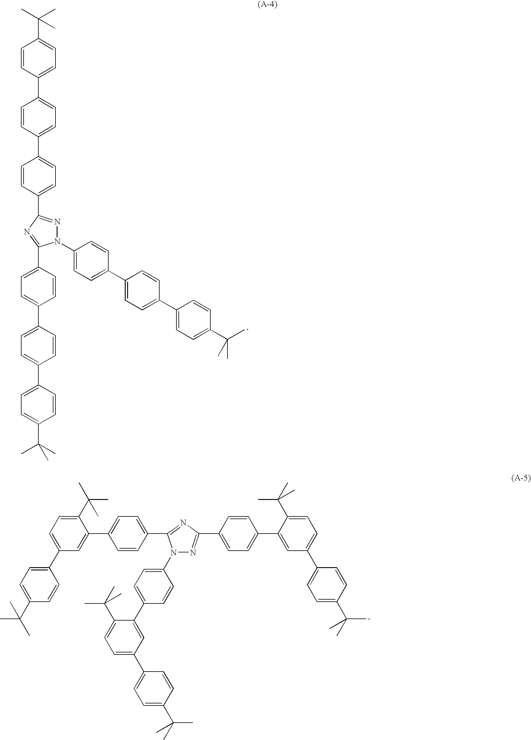


W3 is a group of formula

or —NR70R71, wherein R70 and R71 are independently of each other a group of formula

wherein R72, R73 and R74 are independently of each other hydrogen, C1-C8alkyl, a hydroxyl group, a mercapto group, C1-C8alkoxy, C1-C8alkylthio, halogen, halo-C1-C8alkyl, a cyano group, an aldehyde group, a ketone group, a carboxyl group, an ester group, a carbamoyl group, an amino group, a nitro group, a silyl group or a siloxanyl group, R75, R76, R77 and R78 are independently of each other H, E, C6-C18aryl; C6-C18aryl which is substituted by E; C1-C18alkyl; C1-C18alkyl which is substituted by G and/or interrupted by D; C7-C18aralkyl; or C7-C18aralkyl which is substituted by E; wherein D, E, G, R11, R11′, R12′, R16, R16′, R17, R17′, R30, R31, R32 and R33 are as defined in claim 5; or R70 and R71 together with the nitrogen atom to which they are bonded form a five or six membered heterocyclic ring, such as

which can be condensed by one or two optionally substituted phenyl groups, such as

wherein R216 and R217 independently from each other stands for hydrogen, C1-C8alkyl, C1-C8alkoxy, or phenyl, and
X1 stands for hydrogen, or C1-C8alkyl.

W3 is a group of formula

or —NR70R71, wherein R70 and R71 are independently of each other a group of formula

wherein R18 and R19 are independently of each other C1-C18alkyl, or cyclohexyl, or R70 and R71 together with the nitrogen atom, to which they are bonded, form a group


wherein Ar is W3,
can, for example, be prepared according to a process, which comprises reacting a derivative of formula

wherein R100 stands for halogen such as chloro or bromo, preferably bromo, or E having the meaning of

wherein a is 2 or 3,
with boronic acid derivative
E-Ar, or—in case R100 is not halogen—Hal-Ar,
wherein Hal stands for halogen, preferably for bromo, in the presence of an allylpalladium catalyst of the μ-halo(triisopropylphosphine)(η3-allyl)palladium(II) type (see for example WO99/47474).

can, for example, be prepared according to a process, which comprises reacting a derivative of formula

with a boronic acid derivative E-Ar, wherein E is as defined above.

is, for example, available by reacting

(see, for example, Synthesis (1983) 483).

is, for example, available by reacting

(see, for example, (see, for example, Synthesis (1983) 483).


the electroluminescent device may comprise in this order
(a) an anode, such as, for example, ITO,
(b1) a hole injecting layer, such as, for example, CuPc,
(b2) a hole transporting layer, such as, for example, NPD, or TCTA,
(c) a light-emitting layer, comprising a fluorescent guest compound and a triazole host compound of the present invention, especially a compound A-1 to A-21, or B1 to B4, optionally a positive hole inhibiting layer, such as, for example, BCP,
(d) an electron transporting layer, such as, for example, Alq3, or TPBI and an inorganic compound layer, such as, for example, LiF,
(e) a cathode, such as, for example, Al.

wherein R61 and R62 is a hydrogen atom or an C1-C3alkyl group; R63 through R66 are substituents independently selected from the group consisting of hydrogen, a C1-C6alkyl group, a C1-C6alkoxy group, a halogen atom, a dialkylamino group, a C6-C30aryl group, and the like. Illustrative examples of 4,4′-bis(9-carbazolyl)-1,1′-biphenyl compounds include 4,4′-bis(9-carbazolyl)-1,1′-biphenyl and 4,4′-bis(3-methyl-9-carbazolyl)-1,1′-biphenyl, and the like; or 4,4′,4″-tri-(N-carbazoyl)triphenylamine (TCTA).


Napthalene-1-boronic acid (1.6 g, 0.009 mol) and sodium carbonate (1.0 g in 9 ml water) are stirred under a nitrogen atmosphere and tetrakis(triphenylphospine)palladium (0.1 g, 0.00009 mol) is added to the stirred solution. The stirring is continued at room temperature for 5 minutes and 1-naphthyl boronic acid (1.8 g, 0.0039 mol) dissolved in 27 ml toluene and 5 ml of ethanol is added. Then the reaction mixture is stirred at 85° C. under nitrogen for 24 hours. The reaction mixture is cooled to room temperature and diluted with water. The organic layer is separated and the aqueous layer extracted with ethyl acetate. The combined organic layer is dried, evaporated and the dried solid chromatographed on a silica gel column with hexane:ethyl acetate (98:2) (Yield=0.55 g (18%)).


| Example | Compound | Mp. [° C.] | 1H NMR [ppm, CDCl3] |
| 7 | A-6 | 210-212 | 8.44 (d, J = 8.2 Hz, 2H), 7.92-7.85 (m, 10H), 7.72- |
| 7.70 (m, 6H), 7.61-7.46 (complex m, 15H) | |||
| 8 | A-7 | >240 | 8.41 (d, J = 8.2 Hz, 2H), 8.03-7.9 (m, 3H), 7.81- |
| 7.74 (m, 4H), 7.72-7.3 (complex m, 24H) | |||
| 9 | A-14 | 202-205 | 8.38 (d, J = 8.2 Hz, 2H), 8.1 (s, 1H), 8.0 (s, 1H), |
| 7.98-7.8 (complex m, 9H), 7.8-7.68 (m, 5H), 7.58- | |||
| 7.44 (m, 9H) | |||
| 10 | A-15 | >225 | 8.4 (d, J = 8.2 Hz, 2H), 8.14 (s, 1H), 8.1 (d, J = 5.8 |
| Hz, 2H), 7.98-7.74 (complex m, 20H), 7.64 (d, J = | |||
| 8.2 Hz, 2H), 7.56-7.48 (m, 6H) | |||
| 11 | B-1 | >230 | 8.57(d, J = 7.8 Hz, 2H), 8.18-8.15 (m, 6H), 7.86- |
| 7.73 (complex m, 8H), 7.54-7.42 (complex m, | |||
| 14H), 7.34-7.30 (m, 6H) | |||
| 12 | B-4 | 190-192 | 8.51(d, J = 8.6 Hz, 2H), 8.16 (t, J = 7.04 Hz, 4H), |
| 7.86(d, J = 8.6 Hz, 2H), 7.72 (d, J = 8.2 Hz, 2H), | |||
| 7.64 (d, J = 8.2 Hz, 2H), 7.58-7.50 (complex m, | |||
| 7H), 7.47-7.41(complex m, 6H), 7.31 (t, J = 7.04 | |||
| Hz, 4H) | |||

Compound 1 (Disclosed in WO2004039786)
| Guest | ||||||
| (TBPe) | ||||||
| Appli- | concen- | Bright- | Current | Emission | ||
| cation | tration | ness | efficiency | Voltage | peak | |
| Example | Host | [%] | [cd/m2] | [cd/A] | [V] | [nm] |
| 7 | A-3 | 1.5 | 95 | 2.4 | 9.4 | 463, 490 |
| 8 | A-6 | 2.7 | 110 | 1.7 | 8.0 | 465, 490 |
| 9 | A-14 | 1.6 | 133 | 3.3 | 7.9 | 436, 489 |
| 10 | A-19 | 1.4 | 111 | 1.9 | 8.4 | 465, 491 |
| 11 | A-20 | 2.3 | 107 | 2.7 | 8.3 | 465, 490 |
| 12 | A-21 | 1.8 | 111 | 2.8 | 9.0 | 465, 490 |
| 13 | B-4 | 1.7 | 75 | 2.6 | 8.0 | 466, 492 |
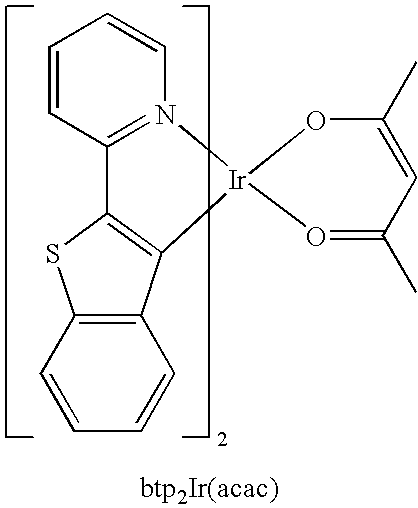 |
| Appli- | Emis- | |||||
| cation | Guest1) | Current | sion | |||
| Exam- | concentration | Brightness | efficiency | Voltage | peak | |
| ple | Host | [%] | [cd/m2] | [cd/A] | [V] | [nm] |
| 14 | A-14 | 8.9 | 81 | 4.1 | 9.6 | 617 |
| 15 | A-20 | 7.9 | 110 | 2.7 | 11.1 | 617 |
| 16 | A-21 | 7.0 | 75 | 3.7 | 10.9 | 616 |
| 1)(btp2Ir(acac). | ||||||
Claims (10)


Applications Claiming Priority (7)
| Application Number | Priority Date | Filing Date | Title |
|---|---|---|---|
| EP05103497 | 2005-04-28 | ||
| EP05103497.3 | 2005-04-28 | ||
| EP05103497 | 2005-04-28 | ||
| EP05107906 | 2005-08-30 | ||
| EP05107906 | 2005-08-30 | ||
| EP05107906.9 | 2005-08-30 | ||
| PCT/EP2006/061670 WO2006114377A1 (en) | 2005-04-28 | 2006-04-19 | Electroluminescent device |
Publications (2)
| Publication Number | Publication Date |
|---|---|
| US20090066231A1 US20090066231A1 (en) | 2009-03-12 |
| US9113536B2 true US9113536B2 (en) | 2015-08-18 |
Family
ID=36443173
Family Applications (1)
| Application Number | Title | Priority Date | Filing Date |
|---|---|---|---|
| US11/919,105 Active 2031-05-06 US9113536B2 (en) | 2005-04-28 | 2006-04-19 | Electroluminescent device |
Country Status (7)
| Country | Link |
|---|---|
| US (1) | US9113536B2 (en) |
| EP (1) | EP1874740B1 (en) |
| JP (1) | JP5138582B2 (en) |
| KR (1) | KR101402633B1 (en) |
| CN (1) | CN101171239B (en) |
| TW (1) | TW200700535A (en) |
| WO (1) | WO2006114377A1 (en) |
Cited By (4)
| Publication number | Priority date | Publication date | Assignee | Title |
|---|---|---|---|---|
| US9806268B2 (en) | 2010-05-21 | 2017-10-31 | Semiconductor Energy Laboratory Co., Ltd. | Triazole derivative, and light-emitting element, light-emitting device, electronic device and lighting device using the triazole derivative |
| US11581487B2 (en) | 2017-04-26 | 2023-02-14 | Oti Lumionics Inc. | Patterned conductive coating for surface of an opto-electronic device |
| US11730012B2 (en) | 2019-03-07 | 2023-08-15 | Oti Lumionics Inc. | Materials for forming a nucleation-inhibiting coating and devices incorporating same |
| US11751415B2 (en) | 2018-02-02 | 2023-09-05 | Oti Lumionics Inc. | Materials for forming a nucleation-inhibiting coating and devices incorporating same |
Families Citing this family (21)
| Publication number | Priority date | Publication date | Assignee | Title |
|---|---|---|---|---|
| US7651791B2 (en) | 2005-12-15 | 2010-01-26 | Idemitsu Kosan Co., Ltd. | Material for organic electroluminescence device and electroluminescence device employing the same |
| WO2007069569A1 (en) * | 2005-12-15 | 2007-06-21 | Idemitsu Kosan Co., Ltd. | Organic electroluminescence element material and organic electroluminescence element using same |
| US20080090834A1 (en) * | 2006-07-06 | 2008-04-17 | Pfizer Inc | Selective azole pde10a inhibitor compounds |
| JP5624784B2 (en) * | 2009-03-31 | 2014-11-12 | 株式会社半導体エネルギー研究所 | Derivatives having heteroaromatic rings, light-emitting elements, light-emitting devices, lighting devices, and electronic devices using derivatives having heteroaromatic rings |
| KR101764599B1 (en) * | 2009-03-31 | 2017-08-03 | 가부시키가이샤 한도오따이 에네루기 켄큐쇼 | Triazole derivative, and light-emitting element, light-emitting device, lighting device, and electronic device using triazole derivative |
| CN106243094A (en) * | 2010-07-08 | 2016-12-21 | Udc 爱尔兰有限责任公司 | By the nitrogen bonding dibenzofurans of 5 yuan of heterocyclic substituted and dibenzothiophenes and the purposes in organic electronic thereof |
| US9067919B2 (en) | 2010-07-08 | 2015-06-30 | Basf Se | Use of dibenzofurans and dibenzothiophenes substituted by nitrogen-bonded five-membered heterocyclic rings in organic electronics |
| JP5699524B2 (en) * | 2010-10-21 | 2015-04-15 | コニカミノルタ株式会社 | Organic photoelectric conversion element and solar cell |
| TWI520952B (en) * | 2010-11-18 | 2016-02-11 | 半導體能源研究所股份有限公司 | Oxadiazole derivative, and light-emitting element, light-emitting device, electronic device, and lighting device using the oxadiazole derivative |
| CN103347886A (en) * | 2010-11-26 | 2013-10-09 | 株式会社半导体能源研究所 | Organometallic complex, light-emitting element, light-emitting device, electronic device, and lighting device |
| KR101910030B1 (en) * | 2010-11-30 | 2018-10-19 | 가부시키가이샤 한도오따이 에네루기 켄큐쇼 | Benzoxazole derivative, light-emitting element, light-emitting device, electronic device, and lighting device |
| WO2012077902A2 (en) | 2010-12-08 | 2012-06-14 | 제일모직 주식회사 | Compound for an organic optoelectronic device, organic light-emitting diode including the compound, and display device including the organic light-emitting diode |
| KR20130009619A (en) * | 2011-07-06 | 2013-01-23 | 가부시키가이샤 한도오따이 에네루기 켄큐쇼 | Light-emitting element, light-emitting device, display device, lighting device, and electronic device |
| EP2963032A4 (en) * | 2013-02-26 | 2016-10-12 | Hodogaya Chemical Co Ltd | Novel naphthotriazole derivative and organic electroluminescence element |
| CN103772305A (en) * | 2014-01-14 | 2014-05-07 | 天津师范大学 | Oxyether triazole compound, and preparation method and application thereof |
| CN113793905A (en) * | 2014-09-26 | 2021-12-14 | Udc 爱尔兰有限责任公司 | Fluorescent organic light emitting element with high efficiency |
| JP2016121288A (en) * | 2014-12-25 | 2016-07-07 | Jnc株式会社 | Optically isotropic liquid crystal medium and optical element |
| CN109912575B (en) * | 2017-12-12 | 2020-07-28 | 中节能万润股份有限公司 | Compound with nitrogen-containing five-membered heterocycle as core and application thereof in organic electroluminescent device |
| CN109912609A (en) * | 2017-12-12 | 2019-06-21 | 江苏三月光电科技有限公司 | It is a kind of using nitrogenous five-ring heterocycles as the compound of parent nucleus and its application on organic electroluminescence device |
| KR102536247B1 (en) * | 2017-12-22 | 2023-05-25 | 삼성디스플레이 주식회사 | Heterocyclic compound and organic light-emitting device comprising the same |
| CN115583941B (en) * | 2022-12-09 | 2023-05-23 | 华南理工大学 | Anthracene-based blue light organic semiconductor material containing triazole, and preparation method and application thereof |
Citations (15)
| Publication number | Priority date | Publication date | Assignee | Title |
|---|---|---|---|---|
| DE1132927B (en) | 1961-04-25 | 1962-07-12 | Basf Ag | Process for the preparation of 2, 3, 5-trisubstituted 1, 2, 4-triazoles |
| US3592656A (en) | 1968-09-03 | 1971-07-13 | Eastman Kodak Co | Photographic silver halide materials supersensitized with a combination of a triazole and a cyanine dye |
| CH542212A (en) | 1966-09-23 | 1973-09-30 | Ciba Geigy Ag | Ethylenic heterocyclic cpds - from corresp methyl cpds and schiff's bases |
| JPS5235300A (en) | 1975-09-12 | 1977-03-17 | Sakai Chem Ind Co Ltd | Curing agents for epoxy resins |
| DD129908A1 (en) | 1977-02-28 | 1978-02-15 | Juergen Liebscher | PROCESS FOR THE PREPARATION OF 1,3,5-TRISUBSTITUTED 1,2,4-TRIAZOLENE |
| JPS56164464A (en) | 1980-05-21 | 1981-12-17 | Tatsuo Nogi | Parallel processing computer |
| US4769292A (en) * | 1987-03-02 | 1988-09-06 | Eastman Kodak Company | Electroluminescent device with modified thin film luminescent zone |
| JP2000100570A (en) | 1998-09-25 | 2000-04-07 | Toray Ind Inc | Luminescent device |
| US20020180347A1 (en) * | 2001-03-02 | 2002-12-05 | Chihaya Adachi | Double doped-layer, phosphorescent organic light emitting devices |
| JP2003005356A (en) | 2001-06-20 | 2003-01-08 | Fuji Photo Film Co Ltd | Negative type resist composition for electron beam or x-ray |
| JP2003109765A (en) | 2001-09-28 | 2003-04-11 | Canon Inc | Organic light emitting element |
| JP2003513961A (en) | 1999-11-09 | 2003-04-15 | ラボラトワール テラメックス | 5-aryl-1H-1,2,4-triazole compounds which are inhibitors of cyclooxygenase-2 and pharmaceutical compositions containing the same |
| JP2004146368A (en) | 2002-10-03 | 2004-05-20 | Konica Minolta Holdings Inc | Organic electroluminescent element and display device |
| JP2004253298A (en) | 2003-02-21 | 2004-09-09 | Konica Minolta Holdings Inc | White light-emitting organic electroluminescent element |
| US6916554B2 (en) * | 2002-11-06 | 2005-07-12 | The University Of Southern California | Organic light emitting materials and devices |
Family Cites Families (2)
| Publication number | Priority date | Publication date | Assignee | Title |
|---|---|---|---|---|
| DE3173083D1 (en) * | 1980-03-22 | 1986-01-16 | Fbc Ltd | Pesticidal heterocyclic compounds, processes for preparing them, compositions containing them, and their use |
| JP2005044790A (en) * | 2003-07-08 | 2005-02-17 | Konica Minolta Holdings Inc | Organic electroluminescent element, illuminator, and display device |
-
2006
- 2006-04-19 US US11/919,105 patent/US9113536B2/en active Active
- 2006-04-19 KR KR1020077027653A patent/KR101402633B1/en active IP Right Grant
- 2006-04-19 JP JP2008508194A patent/JP5138582B2/en active Active
- 2006-04-19 WO PCT/EP2006/061670 patent/WO2006114377A1/en not_active Application Discontinuation
- 2006-04-19 EP EP06743343.3A patent/EP1874740B1/en active Active
- 2006-04-19 CN CN2006800147372A patent/CN101171239B/en active Active
- 2006-04-27 TW TW095115052A patent/TW200700535A/en unknown
Patent Citations (16)
| Publication number | Priority date | Publication date | Assignee | Title |
|---|---|---|---|---|
| DE1132927B (en) | 1961-04-25 | 1962-07-12 | Basf Ag | Process for the preparation of 2, 3, 5-trisubstituted 1, 2, 4-triazoles |
| CH542212A (en) | 1966-09-23 | 1973-09-30 | Ciba Geigy Ag | Ethylenic heterocyclic cpds - from corresp methyl cpds and schiff's bases |
| US3592656A (en) | 1968-09-03 | 1971-07-13 | Eastman Kodak Co | Photographic silver halide materials supersensitized with a combination of a triazole and a cyanine dye |
| JPS5235300A (en) | 1975-09-12 | 1977-03-17 | Sakai Chem Ind Co Ltd | Curing agents for epoxy resins |
| DD129908A1 (en) | 1977-02-28 | 1978-02-15 | Juergen Liebscher | PROCESS FOR THE PREPARATION OF 1,3,5-TRISUBSTITUTED 1,2,4-TRIAZOLENE |
| JPS56164464A (en) | 1980-05-21 | 1981-12-17 | Tatsuo Nogi | Parallel processing computer |
| US4769292A (en) * | 1987-03-02 | 1988-09-06 | Eastman Kodak Company | Electroluminescent device with modified thin film luminescent zone |
| JP2000100570A (en) | 1998-09-25 | 2000-04-07 | Toray Ind Inc | Luminescent device |
| JP2003513961A (en) | 1999-11-09 | 2003-04-15 | ラボラトワール テラメックス | 5-aryl-1H-1,2,4-triazole compounds which are inhibitors of cyclooxygenase-2 and pharmaceutical compositions containing the same |
| US6803380B1 (en) | 1999-11-09 | 2004-10-12 | Laboratoire Theramex | 5-aryl-1h-1,2,4-triazole compounds as inhibitors of cyclooxygenase-2 and pharmaceutical compositions containing them |
| US20020180347A1 (en) * | 2001-03-02 | 2002-12-05 | Chihaya Adachi | Double doped-layer, phosphorescent organic light emitting devices |
| JP2003005356A (en) | 2001-06-20 | 2003-01-08 | Fuji Photo Film Co Ltd | Negative type resist composition for electron beam or x-ray |
| JP2003109765A (en) | 2001-09-28 | 2003-04-11 | Canon Inc | Organic light emitting element |
| JP2004146368A (en) | 2002-10-03 | 2004-05-20 | Konica Minolta Holdings Inc | Organic electroluminescent element and display device |
| US6916554B2 (en) * | 2002-11-06 | 2005-07-12 | The University Of Southern California | Organic light emitting materials and devices |
| JP2004253298A (en) | 2003-02-21 | 2004-09-09 | Konica Minolta Holdings Inc | White light-emitting organic electroluminescent element |
Non-Patent Citations (13)
| Title |
|---|
| Derwent abstract No. 1973-77758U[51] of CH 542 212. |
| English language abstract for JPS52-035300 (1 page); 1977. |
| English language machine-generated translation for DE1132927 (5 pages); 1962. |
| English language machine-generated translation for JP2003-109765 (33 pages); 2003. |
| English language machine-generated translation for JP2004-253298 (108 pages); 2004. |
| Feist, M. et al., "Substituted 2,5-Diary1-2H-Tetrazoles: A combined investigation of their thermal behaviour by simultaneous thermal analysis, mass spectrometry and high-performance liquid chromatography", Journal of Thermal Analysis, 1987, vol. 32, No. 6, pp. 1957-1967. |
| Kato et al., JP (2005)-044790, machine assisted translation. * |
| Kohama et al., JP(2000)-100570, machine assisted translation. * |
| Patent abstracts of Japan 2000-100570. |
| Patent abstracts of Japan 2003-005356. |
| Patent abstracts of Japan 2004-146368. |
| Takahashi et al., JP(2003)-005356, machine assisted translation. * |
| Wolchowe, H., "Triazoles from dibenzamide or di-p-toluamide and hydrazine salts", Monatshefte fuer Chemie, 1916, vol. 37, pp. 473-487. |
Cited By (4)
| Publication number | Priority date | Publication date | Assignee | Title |
|---|---|---|---|---|
| US9806268B2 (en) | 2010-05-21 | 2017-10-31 | Semiconductor Energy Laboratory Co., Ltd. | Triazole derivative, and light-emitting element, light-emitting device, electronic device and lighting device using the triazole derivative |
| US11581487B2 (en) | 2017-04-26 | 2023-02-14 | Oti Lumionics Inc. | Patterned conductive coating for surface of an opto-electronic device |
| US11751415B2 (en) | 2018-02-02 | 2023-09-05 | Oti Lumionics Inc. | Materials for forming a nucleation-inhibiting coating and devices incorporating same |
| US11730012B2 (en) | 2019-03-07 | 2023-08-15 | Oti Lumionics Inc. | Materials for forming a nucleation-inhibiting coating and devices incorporating same |
Also Published As
| Publication number | Publication date |
|---|---|
| KR20080007637A (en) | 2008-01-22 |
| CN101171239A (en) | 2008-04-30 |
| KR101402633B1 (en) | 2014-06-03 |
| EP1874740B1 (en) | 2019-03-06 |
| JP2008539192A (en) | 2008-11-13 |
| WO2006114377A1 (en) | 2006-11-02 |
| US20090066231A1 (en) | 2009-03-12 |
| EP1874740A1 (en) | 2008-01-09 |
| TW200700535A (en) | 2007-01-01 |
| JP5138582B2 (en) | 2013-02-06 |
| CN101171239B (en) | 2013-08-14 |
Similar Documents
| Publication | Publication Date | Title |
|---|---|---|
| US9113536B2 (en) | Electroluminescent device | |
| US8946984B2 (en) | Electroluminescent device | |
| US11968893B2 (en) | Electroluminescent device | |
| US8012602B2 (en) | Electroluminescent device | |
| US20080199726A1 (en) | Electroluminescent Device | |
| US20090102373A1 (en) | Electroluminescent device | |
| EP1687856B1 (en) | Electroluminescent devices comprising 2-(p-triphenyl)-3-phenyl-pyrazine derivatives | |
| US20060226766A1 (en) | Electroluminescent device |
Legal Events
| Date | Code | Title | Description |
|---|---|---|---|
| AS | Assignment |
Owner name: CIBA SPECIALTY CHEMICALS CORP., NEW YORK Free format text: ASSIGNMENT OF ASSIGNORS INTEREST;ASSIGNORS:OKA, HIDETAKA;JOSHI, RAMACHANDRA V.;TANABE, JUNICHI;AND OTHERS;SIGNING DATES FROM 20070816 TO 20070911;REEL/FRAME:021959/0702 Owner name: CIBA SPECIALTY CHEMICALS CORP., NEW YORK Free format text: ASSIGNMENT OF ASSIGNORS INTEREST;ASSIGNORS:OKA, HIDETAKA;JOSHI, RAMACHANDRA V.;TANABE, JUNICHI;AND OTHERS;REEL/FRAME:021959/0702;SIGNING DATES FROM 20070816 TO 20070911 |
|
| AS | Assignment |
Owner name: BASF SE, GERMANY Free format text: ASSET TRANSFER AGREEMENT;ASSIGNOR:CIBA CORPORATION;REEL/FRAME:035827/0520 Effective date: 20090702 |
|
| STCF | Information on status: patent grant |
Free format text: PATENTED CASE |
|
| FEPP | Fee payment procedure |
Free format text: PAYOR NUMBER ASSIGNED (ORIGINAL EVENT CODE: ASPN); ENTITY STATUS OF PATENT OWNER: LARGE ENTITY |
|
| AS | Assignment |
Owner name: UDC IRELAND LIMITED, IRELAND Free format text: ASSIGNMENT OF ASSIGNORS INTEREST;ASSIGNOR:BASF SE;REEL/FRAME:039460/0615 Effective date: 20160628 |
|
| AS | Assignment |
Owner name: UDC IRELAND LIMITED, IRELAND Free format text: CORRECTIVE ASSIGNMENT TO CORRECT THE INCORRECT APPL. NO. 14/901,736 PREVIOUSLY RECORDED AT REEL: 039460 FRAME: 0615. ASSIGNOR(S) HEREBY CONFIRMS THE ASSIGNMENT;ASSIGNOR:BASF SE;REEL/FRAME:042740/0222 Effective date: 20160628 |
|
| MAFP | Maintenance fee payment |
Free format text: PAYMENT OF MAINTENANCE FEE, 4TH YEAR, LARGE ENTITY (ORIGINAL EVENT CODE: M1551); ENTITY STATUS OF PATENT OWNER: LARGE ENTITY Year of fee payment: 4 |
|
| MAFP | Maintenance fee payment |
Free format text: PAYMENT OF MAINTENANCE FEE, 8TH YEAR, LARGE ENTITY (ORIGINAL EVENT CODE: M1552); ENTITY STATUS OF PATENT OWNER: LARGE ENTITY Year of fee payment: 8 |