US910643A - Apparatus for magnetic treatment of diseases. - Google Patents
Apparatus for magnetic treatment of diseases. Download PDFInfo
- Publication number
- US910643A US910643A US40827807A US1907408278A US910643A US 910643 A US910643 A US 910643A US 40827807 A US40827807 A US 40827807A US 1907408278 A US1907408278 A US 1907408278A US 910643 A US910643 A US 910643A
- Authority
- US
- United States
- Prior art keywords
- magnets
- battery
- magnetic
- diseases
- pole pieces
- Prior art date
- Legal status (The legal status is an assumption and is not a legal conclusion. Google has not performed a legal analysis and makes no representation as to the accuracy of the status listed.)
- Expired - Lifetime
Links
- 201000010099 disease Diseases 0.000 title description 9
- 208000037265 diseases, disorders, signs and symptoms Diseases 0.000 title description 9
- 239000000696 magnetic material Substances 0.000 description 10
- 239000004020 conductor Substances 0.000 description 5
- 230000008878 coupling Effects 0.000 description 4
- 238000010168 coupling process Methods 0.000 description 4
- 238000005859 coupling reaction Methods 0.000 description 4
- 239000003795 chemical substances by application Substances 0.000 description 3
- 230000000246 remedial effect Effects 0.000 description 3
- XEEYBQQBJWHFJM-UHFFFAOYSA-N Iron Chemical compound [Fe] XEEYBQQBJWHFJM-UHFFFAOYSA-N 0.000 description 2
- BGPVFRJUHWVFKM-UHFFFAOYSA-N N1=C2C=CC=CC2=[N+]([O-])C1(CC1)CCC21N=C1C=CC=CC1=[N+]2[O-] Chemical compound N1=C2C=CC=CC2=[N+]([O-])C1(CC1)CCC21N=C1C=CC=CC1=[N+]2[O-] BGPVFRJUHWVFKM-UHFFFAOYSA-N 0.000 description 2
- 239000012530 fluid Substances 0.000 description 2
- 239000000463 material Substances 0.000 description 2
- 238000004804 winding Methods 0.000 description 2
- 102100024133 Coiled-coil domain-containing protein 50 Human genes 0.000 description 1
- 101000910772 Homo sapiens Coiled-coil domain-containing protein 50 Proteins 0.000 description 1
- 230000002745 absorbent Effects 0.000 description 1
- 239000002250 absorbent Substances 0.000 description 1
- 239000012141 concentrate Substances 0.000 description 1
- 238000010586 diagram Methods 0.000 description 1
- 229910052742 iron Inorganic materials 0.000 description 1
- 230000007935 neutral effect Effects 0.000 description 1
Images
Classifications
-
- A—HUMAN NECESSITIES
- A61—MEDICAL OR VETERINARY SCIENCE; HYGIENE
- A61N—ELECTROTHERAPY; MAGNETOTHERAPY; RADIATION THERAPY; ULTRASOUND THERAPY
- A61N2/00—Magnetotherapy
- A61N2/02—Magnetotherapy using magnetic fields produced by coils, including single turn loops or electromagnets
Definitions
- This invention has reference to improvements in apparatus for magnetic treatment of diseases, and its object is to provide means whereby the diseased tissue ma be located within a magnetic field, which latter may be made intense or weak as desired, and may be made to include a greater or less area of the diseased portion of the body, and further may be so arranged that remedial agents may be applied to the pole pieces.
- the invention therefore comprises a series of electro-magnets with acharging source, such as a battery, with means for coupling up the magnets and the battery in such order that the magnetic field produced may be of the desired strength.
- acharging source such as a battery
- the pole pieces may be adjusted to any part of the body with great facility and may be placed at any distance apart to include a greater or less area.
- a base board 1 which may be of any suitable shape and is designed to be placed upon a suitable support or stand. Near one end of this board is provided a casing 2 simply indicated in outline in the drawing, and in this casing is inclosed a battery 3 constituting a source of electric current.
- the battery is Specification of Letters Patent.
- One terminal of the battery is connected by a conductor 6 to an ordinary single point switch 7, and the contact block of this switch is connected by a conductor 8 to branch conductors 9 leading each to the terminal of the winding 10 of a corresponding bar magnet 5.
- the other terminals of the winding of each bar electro-magnet 5 is connected by a respective conductor 11 to a contact strip 12 in the path of a corresponding brush 13 upon a switch lever 14.
- the path of still another brush 15 carried by the switch lever are a series of contacts 16, each of which is connected by a conductor 17 to the battery.
- the arrangement is such that when the brush 15 is u on one end of the contact 16, then one cc of the battery is included in the circuit. When the brush 15 is upon the second contact then two cells are included.
- Each end of the core of each bar electromagnet 5 is pointed to concentrate the lines of force, and leading from such pointed ends are iron wires or rods 18 ultimately joined, as shown at 19, and from these joined ends lead other wires or rods 20 of such nature as to be more or less flexible and'constituting' extended pole pieces for the magnets.
- the free ends of the strands 20 terminate in clips 21 which should be of magnetic material, and these clips engage and hold pole pieces 22, also of magnetic material.
- the free ends of the pole pieces 22 are provided with some absorbent material 23, such, for instance, as sponge, for the application of remedial agents in fluid form.
- a magnetometer 24 having on each side a scale 25.
- the pole pieces 22 may be placed upon the scale and should, when the battery circuits are closed, deflect the magnetic needle to a certain definite ex tent. For instance, suppose that one of the pole pieces was placed upon the index point numbered 1 and a single cell or battery was included in the circuit. Then there is a certain definite deflection of the needle and this deflection is brought back to the neutral point by the placing of the other pole piece 22 upon the corresponding index point on the other side of the magnetometer.
- the deflection should be the same as for one cell when the pole piece is placed upon the index 2, and so on through the seven points, the deflection being the same for the corresponding number of magnets and batteries included.
- a remedial agent may be placed upon the appropriate pole piece 22, and the pole pieces are placed u on the skin of the patient in the neighbor iood of the diseased tissue, and the magnetic field is made weak or strong, depending upon the conditions present and the depth of the diseased tissues below the skin.
- the time of application of the magnetic forces depends of the attendant physician since no hard and fast rules can be formulated.
- the strands 20 should be suitably insulated or protected so as not to come into actual physical contact, for this would tend to short circuit the magnetic lines of force and either weaken or obliterate the magnetic field between the pole pieces 22.
- the physician using the instrument may with confidence set the switch 14 to the position to include one, two or more of the electroanagnets up to the full strength of the instrument, as his judgment may dictate.
- the instrument has been used for some time then the voltage of the batteries drops and the magnets are no longer charged to the initial extent. Under these circumstances it is necessary for the attending physician to place the pole pieces 22 upon the magnetometer scale and the switch arm 14 is moved until the required indication of the magnetometer needle is obtained, and this will be irrespective.
- a magnetic apparatus for the treatment of diseases comprising a number of electro-magnets having their like polar ends connected in multiple, flexible magnetic strands leading from the connected ends of the magnets, and pole pieces carried by the free ends of the flexible strands, the strands and pole pieces being made of magnetic material.
- An instrument for the magnetic treatment of diseases comprising a number of electro-magnets having their like polar ends connected in multiple, strands of magnetic material leading from the connected ends. of the magnets, pole pieces of magnetic mate rial carried by the free ends of the strands, a source of electric current, and means for coupling the coils of the electromagnets in dividually into multiple arc relation with the source of current.
- An instrument for the magnetic treatment of diseases comprising a series of bar elcctro-magnets having their polar ends tapering and connected together in multiple arc, flexible strands of magnetic material extending from the connected ends of the bar magnets, pole pieces of magnetic material connected to the free ends of the flexible strands, a battery, and a switch for connecting the. battery to the coils of electro-mag nets comprising a switch arm carryinga. se-
- An instrument for the magnetic treatment of diseases comprising a series of bar electro-magnets having their polar ends tapering and connected together in multiple arc, flexible strands of magnetic material eX- tending from the connected ends of the bar magnets, pole pieces of magnetic material connected to the free ends of the flexible strands, a battery, and a switch for connecting the battery to the coils of electro-magnets comprising a switch arm carrying a series of brushes, and contacts in the path of the brushes, said contacts being of different lengths and connected respectively to the magnet coils, another brush on the switch arm, battery terminals in the path of the lastnamed brush for coupling up the battery to the respective magnet coils in regular order, and a magnetometer associated with the electro-magnets and source of power therefor for determining the strength of the magnets irrespective of the number of batteries connected therewith.
Landscapes
- Health & Medical Sciences (AREA)
- Engineering & Computer Science (AREA)
- Biomedical Technology (AREA)
- Nuclear Medicine, Radiotherapy & Molecular Imaging (AREA)
- Radiology & Medical Imaging (AREA)
- Life Sciences & Earth Sciences (AREA)
- Animal Behavior & Ethology (AREA)
- General Health & Medical Sciences (AREA)
- Public Health (AREA)
- Veterinary Medicine (AREA)
- Magnetic Treatment Devices (AREA)
Description
R. s. OL YMER. APPARATUS FOR MAGNETIC TREATMENT OF DISEASES.
APPLICATION FILED DEC. 27. 1907 910,643.
Patented Jan. 26, 1909.
REUBEN S. GLYMEP, OF ALLENTOWN, PENNSYLVANIA.
APPARATUS FOR MAGNETIC TREATMENT OF DISEASES.
Application filed December 27, 1907.
To all whom it may concern:
Be it known that I, REUBEN S. CLYMER, a citizen of the United States, residing at Allentown, in the county of Lehigh and State of Pennsylvania, have invented a new and useful Apparatus for Magnetic Treatment of Diseases, of which the following is a specification.
This invention has reference to improvements in apparatus for magnetic treatment of diseases, and its object is to provide means whereby the diseased tissue ma be located within a magnetic field, which latter may be made intense or weak as desired, and may be made to include a greater or less area of the diseased portion of the body, and further may be so arranged that remedial agents may be applied to the pole pieces.
Such pole pieces must oftentimes be placed at different distances apart and, therefore, it
is necessary to regulate the magnetizing forces in order that the magnetic field may be strong or weak, as required.
The invention therefore comprises a series of electro-magnets with acharging source, such as a battery, with means for coupling up the magnets and the battery in such order that the magnetic field produced may be of the desired strength. By using a number of electro-magnets and connecting their like poles together in multiple, and by then extending these poles by suitable magnetic material to suitable pole pieces the connecting strand of the material being of such form as to be flexible, the pole pieces may be adjusted to any part of the body with great facility and may be placed at any distance apart to include a greater or less area.
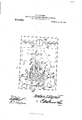
The invention, however, willbe best un derstood by a consideration of the following detail description taken in connection with the accompanying drawings forming a part of this specification, in which drawing the figure is a diagram showing the arrangement of the apparatus forming the subject-matter of this invention.
Referring to the drawing there is shown a base board 1, which may be of any suitable shape and is designed to be placed upon a suitable support or stand. Near one end of this board is provided a casing 2 simply indicated in outline in the drawing, and in this casing is inclosed a battery 3 constituting a source of electric current. The battery is Specification of Letters Patent.
Patented Jan. 26, 1909.
Serial No. 408,278.
shown as consisting of seven elements, but may consist of more or less as desired.
Near the other end of the base board is another casing 1 simply indicated in outline, and within this casing are supported a number of bar electro-magnets 5, shown in the drawing as seven in number, but the number may be varied as desired.
One terminal of the battery is connected by a conductor 6 to an ordinary single point switch 7, and the contact block of this switch is connected by a conductor 8 to branch conductors 9 leading each to the terminal of the winding 10 of a corresponding bar magnet 5. The other terminals of the winding of each bar electro-magnet 5 is connected by a respective conductor 11 to a contact strip 12 in the path of a corresponding brush 13 upon a switch lever 14. 1n the path of still another brush 15 carried by the switch lever, are a series of contacts 16, each of which is connected by a conductor 17 to the battery. The arrangement is such that when the brush 15 is u on one end of the contact 16, then one cc of the battery is included in the circuit. When the brush 15 is upon the second contact then two cells are included. i Vhen the brush 15 is upon the third contact then three cells are included, and when the brush 15 is upon the fourth contact, which is a long contact, then all seven cells are included. There are as many brushes 13 as there are contacts 12, and these contacts 12 are of different lengths so that when the brushes 13 are caused to sweep over these contacts the respective coils 10 of the bar electro-magnets 5 will be cut in or out of circuit, as the case may be. Now, let it be supposed that the switch lever 14 is swung to the left, as viewed in the figure, until a brush 15 is upon the contact 16 farthest to the left, and the corresponding brush 13 is upon the longest of the contacts 12. Under these circumstances, the first cell of the battery to the left is coupled up to that bar magnet 5 in circuit with the longest contact 12. Now, if the lever 14 be moved to the right until the brush 15 is upon the second contact, then two brushes 13 will be upon the longest and the next to the lon est contacts 12. This will include two bar e cotro-magnets in the circuit in multiple are. A further movement of the switch lever 14 to the right will include three bar magnets, then four bar magnets, and so on until they are all included in multiple arc with the battery. At any time, however, and under any condition of the switch lever 14, the circuit may be broken at the switch 7.
Each end of the core of each bar electromagnet 5 is pointed to concentrate the lines of force, and leading from such pointed ends are iron wires or rods 18 ultimately joined, as shown at 19, and from these joined ends lead other wires or rods 20 of such nature as to be more or less flexible and'constituting' extended pole pieces for the magnets. The free ends of the strands 20 terminate in clips 21 which should be of magnetic material, and these clips engage and hold pole pieces 22, also of magnetic material. The free ends of the pole pieces 22 are provided with some absorbent material 23, such, for instance, as sponge, for the application of remedial agents in fluid form.
At one end of the base board 1 is mounted a magnetometer 24 having on each side a scale 25. By this means the pole pieces 22 may be placed upon the scale and should, when the battery circuits are closed, deflect the magnetic needle to a certain definite ex tent. For instance, suppose that one of the pole pieces was placed upon the index point numbered 1 and a single cell or battery was included in the circuit. Then there is a certain definite deflection of the needle and this deflection is brought back to the neutral point by the placing of the other pole piece 22 upon the corresponding index point on the other side of the magnetometer. If two cells of battery be included then the deflection should be the same as for one cell when the pole piece is placed upon the index 2, and so on through the seven points, the deflection being the same for the corresponding number of magnets and batteries included. By this means it is possible to always adjust the magnetic strength even when the batteries become weak and the magnets are not brought up to their full strength as before, although of course the maximum strength cannot then be attained, but magnetic strength somewhat less than the maximum may be had with the weaker battery, and this is at once apparent from the test with the magnetometer. Suppose, now that it is desirable to treat diseases with the instrument described. A remedial agent may be placed upon the appropriate pole piece 22, and the pole pieces are placed u on the skin of the patient in the neighbor iood of the diseased tissue, and the magnetic field is made weak or strong, depending upon the conditions present and the depth of the diseased tissues below the skin. The time of application of the magnetic forces depends of the attendant physician since no hard and fast rules can be formulated.
The strands 20 should be suitably insulated or protected so as not to come into actual physical contact, for this would tend to short circuit the magnetic lines of force and either weaken or obliterate the magnetic field between the pole pieces 22.
Assuming that the batteries are of normal strength, then the physician using the instrument may with confidence set the switch 14 to the position to include one, two or more of the electroanagnets up to the full strength of the instrument, as his judgment may dictate. When, however, the instrument has been used for some time then the voltage of the batteries drops and the magnets are no longer charged to the initial extent. Under these circumstances it is necessary for the attending physician to place the pole pieces 22 upon the magnetometer scale and the switch arm 14 is moved until the required indication of the magnetometer needle is obtained, and this will be irrespective. of the number of magnets included in the circuit, the only difference then being that the maxi mum magnetic ei'lect cannot under these conditions be obtaine When the batteries have run down to too great an extent then they may be replaced by fresh batteries if of the dry cell type, or recharged if fluid batteries or storage batteries.
What is claimed is 1. A magnetic apparatus for the treatment of diseases comprising a number of electro-magnets having their like polar ends connected in multiple, flexible magnetic strands leading from the connected ends of the magnets, and pole pieces carried by the free ends of the flexible strands, the strands and pole pieces being made of magnetic material.
2. An instrument for the magnetic treatment of diseases comprising a number of electro-magnets having their like polar ends connected in multiple, strands of magnetic material leading from the connected ends. of the magnets, pole pieces of magnetic mate rial carried by the free ends of the strands, a source of electric current, and means for coupling the coils of the electromagnets in dividually into multiple arc relation with the source of current.
3. An instrument for the magnetic treatment of diseases, comprising a series of bar elcctro-magnets having their polar ends tapering and connected together in multiple arc, flexible strands of magnetic material extending from the connected ends of the bar magnets, pole pieces of magnetic material connected to the free ends of the flexible strands, a battery, and a switch for connecting the. battery to the coils of electro-mag nets comprising a switch arm carryinga. se-
'ries of brushes, and contacts in the path of the brushes, said contacts being of dilierent lengths and connected respectively to the magnet coils, another brush on the switch arm, and battery terminals in the path of the last-named brush for coupling up the battery to the respective magnet coils in regular order.
4. An instrument for the magnetic treatment of diseases, comprising a series of bar electro-magnets having their polar ends tapering and connected together in multiple arc, flexible strands of magnetic material eX- tending from the connected ends of the bar magnets, pole pieces of magnetic material connected to the free ends of the flexible strands, a battery, and a switch for connecting the battery to the coils of electro-magnets comprising a switch arm carrying a series of brushes, and contacts in the path of the brushes, said contacts being of different lengths and connected respectively to the magnet coils, another brush on the switch arm, battery terminals in the path of the lastnamed brush for coupling up the battery to the respective magnet coils in regular order, and a magnetometer associated with the electro-magnets and source of power therefor for determining the strength of the magnets irrespective of the number of batteries connected therewith.
In testimony that I claim the foregoing as my own, I have hereto ai'fixed my signature in the presence of two witnesses.
REUBEN S. CLYMER.
Vl itnesses:
ROBERT D. SOHAADT, MARY ODONNELL.
Priority Applications (1)
| Application Number | Priority Date | Filing Date | Title |
|---|---|---|---|
| US40827807A US910643A (en) | 1907-12-27 | 1907-12-27 | Apparatus for magnetic treatment of diseases. |
Applications Claiming Priority (1)
| Application Number | Priority Date | Filing Date | Title |
|---|---|---|---|
| US40827807A US910643A (en) | 1907-12-27 | 1907-12-27 | Apparatus for magnetic treatment of diseases. |
Publications (1)
| Publication Number | Publication Date |
|---|---|
| US910643A true US910643A (en) | 1909-01-26 |
Family
ID=2979081
Family Applications (1)
| Application Number | Title | Priority Date | Filing Date |
|---|---|---|---|
| US40827807A Expired - Lifetime US910643A (en) | 1907-12-27 | 1907-12-27 | Apparatus for magnetic treatment of diseases. |
Country Status (1)
| Country | Link |
|---|---|
| US (1) | US910643A (en) |
-
1907
- 1907-12-27 US US40827807A patent/US910643A/en not_active Expired - Lifetime
Similar Documents
| Publication | Publication Date | Title |
|---|---|---|
| Kouwenhoven et al. | The current flowing through the heart under conditions of electric shock | |
| MX147342A (en) | IMPROVEMENTS IN APPARATUS FOR THE CONTROLLED MODIFICATION OF GROWTH BEHAVIOR REPAIR AND MAINTENANCE OF LIVING TISSUE OR CELLS THROUGH CODED ELECTRICAL INFORMATION | |
| US2477653A (en) | Primary electrical training test board apparatus | |
| SE509746C2 (en) | NMR apparatus for examining a body, in particular for imaging the human body's skin, and apparatus for generating a magnetic field gradient in such an apparatus | |
| US910643A (en) | Apparatus for magnetic treatment of diseases. | |
| US3201754A (en) | Remote control and indication system | |
| DE69021340D1 (en) | Pacemaker probe with additional stimulation pole. | |
| US3243795A (en) | Battery condition indicator | |
| US1433264A (en) | Electrical testing instrument | |
| US3493863A (en) | Portable battery tester | |
| US708478A (en) | Electrical position-indicator. | |
| US670278A (en) | Reversing apparatus for electrical device. | |
| US345755A (en) | Electrical indicator | |
| US743373A (en) | Electromagnetic therapeutic apparatus. | |
| US647006A (en) | Special apparatus for electric baths. | |
| US414310A (en) | And charles e | |
| US1159354A (en) | Electrical testing apparatus. | |
| US332480A (en) | Magneto-electric indicator | |
| SU721777A1 (en) | Arrangement for locating fault to the sheathing of power cable | |
| US672989A (en) | Transformer. | |
| USRE1386E (en) | Improvement in electric baths | |
| US39733A (en) | Improvement in remedial | |
| US786533A (en) | Electric exercising appliance. | |
| US417923A (en) | Frederick j | |
| US619448A (en) | tomney |