US9091336B2 - Circulating element for ball screw and ball screw using the circulating element - Google Patents

Circulating element for ball screw and ball screw using the circulating element Download PDF

Info

Publication number
US9091336B2
US9091336B2 US13/944,219 US201313944219A US9091336B2 US 9091336 B2 US9091336 B2 US 9091336B2 US 201313944219 A US201313944219 A US 201313944219A US 9091336 B2 US9091336 B2 US 9091336B2
Authority
US
United States
Prior art keywords
inclined plane
circulating
lateral side
passage
circulating element
Prior art date
Legal status (The legal status is an assumption and is not a legal conclusion. Google has not performed a legal analysis and makes no representation as to the accuracy of the status listed.)
Active, expires
Application number
US13/944,219
Other versions
US20140182407A1 (en
Inventor
Ming-Yao Lin
Ming-Che Kuo
Current Assignee (The listed assignees may be inaccurate. Google has not performed a legal analysis and makes no representation or warranty as to the accuracy of the list.)
Hiwin Technologies Corp
Original Assignee
Hiwin Technologies Corp
Priority date (The priority date is an assumption and is not a legal conclusion. Google has not performed a legal analysis and makes no representation as to the accuracy of the date listed.)
Filing date
Publication date
Application filed by Hiwin Technologies Corp filed Critical Hiwin Technologies Corp
Assigned to HIWIN TECHNOLOGIES CORP. reassignment HIWIN TECHNOLOGIES CORP. ASSIGNMENT OF ASSIGNORS INTEREST (SEE DOCUMENT FOR DETAILS). Assignors: KUO, MING-CHE, LIN, MING-YAO
Publication of US20140182407A1 publication Critical patent/US20140182407A1/en
Application granted granted Critical
Publication of US9091336B2 publication Critical patent/US9091336B2/en
Active legal-status Critical Current
Adjusted expiration legal-status Critical

Links

Images

Classifications

    • FMECHANICAL ENGINEERING; LIGHTING; HEATING; WEAPONS; BLASTING
    • F16ENGINEERING ELEMENTS AND UNITS; GENERAL MEASURES FOR PRODUCING AND MAINTAINING EFFECTIVE FUNCTIONING OF MACHINES OR INSTALLATIONS; THERMAL INSULATION IN GENERAL
    • F16HGEARING
    • F16H25/00Gearings comprising primarily only cams, cam-followers and screw-and-nut mechanisms
    • F16H25/18Gearings comprising primarily only cams, cam-followers and screw-and-nut mechanisms for conveying or interconverting oscillating or reciprocating motions
    • F16H25/20Screw mechanisms
    • F16H25/22Screw mechanisms with balls, rollers, or similar members between the co-operating parts; Elements essential to the use of such members
    • F16H25/2204Screw mechanisms with balls, rollers, or similar members between the co-operating parts; Elements essential to the use of such members with balls
    • F16H25/2214Screw mechanisms with balls, rollers, or similar members between the co-operating parts; Elements essential to the use of such members with balls with elements for guiding the circulating balls
    • FMECHANICAL ENGINEERING; LIGHTING; HEATING; WEAPONS; BLASTING
    • F16ENGINEERING ELEMENTS AND UNITS; GENERAL MEASURES FOR PRODUCING AND MAINTAINING EFFECTIVE FUNCTIONING OF MACHINES OR INSTALLATIONS; THERMAL INSULATION IN GENERAL
    • F16HGEARING
    • F16H25/00Gearings comprising primarily only cams, cam-followers and screw-and-nut mechanisms
    • F16H25/18Gearings comprising primarily only cams, cam-followers and screw-and-nut mechanisms for conveying or interconverting oscillating or reciprocating motions
    • F16H25/20Screw mechanisms
    • F16H25/22Screw mechanisms with balls, rollers, or similar members between the co-operating parts; Elements essential to the use of such members
    • YGENERAL TAGGING OF NEW TECHNOLOGICAL DEVELOPMENTS; GENERAL TAGGING OF CROSS-SECTIONAL TECHNOLOGIES SPANNING OVER SEVERAL SECTIONS OF THE IPC; TECHNICAL SUBJECTS COVERED BY FORMER USPC CROSS-REFERENCE ART COLLECTIONS [XRACs] AND DIGESTS
    • Y10TECHNICAL SUBJECTS COVERED BY FORMER USPC
    • Y10TTECHNICAL SUBJECTS COVERED BY FORMER US CLASSIFICATION
    • Y10T74/00Machine element or mechanism
    • Y10T74/19Gearing
    • Y10T74/19642Directly cooperating gears
    • Y10T74/19698Spiral
    • Y10T74/19702Screw and nut
    • Y10T74/19744Rolling element engaging thread
    • Y10T74/19749Recirculating rolling elements
    • Y10T74/19767Return path geometry

Definitions

  • the present invention relates to linear transmission technology and more particularly, to a circulating element for ball screw and a ball screw using the circulating element.
  • FIG. 1 illustrates a prior art ball screw 10 , which is characterized by the formation of a mounting groove 16 in the hole wall of an axial hole 15 of a screw nut 13 for accommodating a circulating element 17 , which defines therein a circulating passage 18 that is connected to an internal thread groove 14 of a screw nut 13 , thus, balls 19 can move through a circulating passage that is formed of an external thread groove 12 of a screw shaft 11 , an internal thread groove 14 of a screw nut 13 and the circulating passage 18 of the circulating element 17 .
  • This type of circulating element 17 can be used only under the condition that the screw nut 13 has an external thread groove located on its one end and linked to the equipment, or the internal thread groove 14 of the screw nut 13 has a short pitch, or the screw nut 13 of the ball screw has a small outer diameter. Due to the structural limitations of the screw nut, the aforesaid prior art circulating element 17 cannot be replaced by a commonly known external circulating or end plug circulating type circulating element.
  • the mounting groove 16 of the screw nut 13 is made by electrical discharge wire-cutting technology. Except the drawback of high processing cost, the mounting groove 16 will extend through the two opposite ends of the screw nut 13 after the processing. Thus, when mounting the circulating element 17 in the mounting groove 16 , it is necessary to constantly adjust the position of the circulating element 17 . If position deviation occurs, connection between the circulating passage 18 and the internal thread groove 14 may be unable to achieve, resulting in an alignment problem, as shown in FIG. 2 . When an alignment problem occurs, the moving smoothness of the balls 19 will be affected. If the balls 19 do not move smoothly, they will continuously impact the circulating element 17 , causing circulating element damage or ball damage.
  • the balls 19 when loading the balls 19 , the balls 19 must be loaded by lots to match the position of the circulating passage 18 , i.e., load a first lot of balls 19 in the external thread groove 12 , the internal thread groove 14 and the first circulating passage 18 at first, and then load a second lot of balls 19 in the external thread groove 12 , the internal thread groove 14 and the second circulating passage 18 , and so on, until all of the balls 19 have been loaded in every circulating passage 18 .
  • This ball loading procedure is complicated.
  • the aforesaid prior art technique has the drawbacks of high processing costs, assembly difficulty, low alignment accuracy, and poor running smoothness.
  • the present invention has been accomplished under the circumstances in view. It is the main object of the present invention to provide a circulating element for ball screw, which enables the ball screw to have the advantages of low processing costs, ease of assembly, high alignment accuracy, and excellent running smoothness.
  • a circulating element in accordance with the present invention comprises a first surface, and a second surface opposite to the first surface.
  • the circulating element comprises a circulating passage located on the first surface.
  • the circulating passage extends from one side of the first surface to the other side of the first surface, having a coupling mouth located on each of two opposite ends thereof.
  • the second surface of the circulating element comprises a coupling groove disposed between the two coupling mouths of the circulating passage.
  • the second surface of the circulating element curves inwardly in direction toward the second surface to fit the outer surface of a screw shaft of the ball screw.
  • the first surface of the circulating element defines two inclined planes inclining in reversed directions.
  • One inclined plane of the circulating passage extends along the length of the circulating element to the other inclined plane.
  • the circulating element comprises at least one mounting hole cut through the first surface and the second surface.
  • FIG. 1 is an exploded view of a ball screw according to the prior art.
  • FIG. 2 is a sectional view of a part of the prior art ball screw, illustrating the mounting relationship between the screw nut and the circulating element.
  • FIG. 3 is an oblique top elevational view of a ball screw in accordance with a first embodiment of the present invention.
  • FIG. 4 is an exploded view of the ball screw in accordance with the first embodiment of the present invention.
  • FIG. 5 is a sectional view of the screw nut of the ball screw in accordance with the first embodiment of the present invention.
  • FIG. 6 is an elevational view of a circulating element for ball screw in accordance with the first embodiment of the present invention.
  • FIG. 7 is an end view of the circulating element for ball screw in accordance with the first embodiment of the present invention.
  • FIG. 8 is a top view of the circulating element for ball screw in accordance with the first embodiment of the present invention.
  • FIG. 9 is a bottom view of the circulating element for ball screw in accordance with the first embodiment of the present invention.
  • FIG. 10 is a sectional elevation of the ball screw in accordance with the first embodiment of the present invention, illustrating the relationship between the internal thread groove of the screw nut and the coupling groove of the circulating element.
  • FIG. 11 is a sectional plain view of the ball screw in accordance with the first embodiment of the present invention, illustrating the relationship between the coupling groove of the circulating element and the external thread groove of the screw shaft.
  • FIG. 12 is a sectional plain view of the ball screw in accordance with the first embodiment of the present invention, illustrating the relationship between the external thread groove of the screw shaft/the internal thread groove of the screw nut and the circulating passage of the circulating element.
  • FIG. 13 is an exploded view of the ball screw in accordance with the first embodiment of the present invention.
  • FIG. 14 is an exploded view of the circulating element for ball screw in accordance with the first embodiment of the present invention.
  • FIG. 15 is an exploded view of the circulating element for ball screw in accordance with the first embodiment of the present invention.
  • FIG. 16 is an exploded view of an alternate form of the circulating element for ball screw in accordance with the first embodiment of the present invention.
  • FIG. 17 is an elevational view of a circulating element for ball screw in accordance with a second embodiment of the present invention.
  • FIG. 18 is an elevational view of a ball screw in accordance with the second embodiment of the present invention.
  • FIG. 19 is another elevational view of the circulating element for ball screw in accordance with a second embodiment of the present invention.
  • FIG. 20 is another exploded view of the ball screw in accordance with the second embodiment of the present invention.
  • the ball screw 20 comprises a screw shaft 30 , a screw nut 40 , and a plurality of balls 50 .
  • the screw shaft 30 comprises an external thread groove 32 .
  • the screw nut 40 comprises an axial hole 41 , which receives the screw shaft 30 for allowing the screw nut 40 to be axially moved along the screw shaft 30 , and a mounting groove 42 and an internal thread groove 43 formed in the hole wall of the axial hole 41 and abutted against each other.
  • the mounting groove 42 extends from one end edge of the screw nut 40 axially along the extending direction of the axial hole 41 .
  • the mounting groove 42 has one end thereof terminating in a bearing surface 44 (see FIGS. 5 and 11 ).
  • the internal thread groove 43 corresponds to the external thread groove 32 of the screw shaft 30 , defining with the external thread groove 32 a first passage 51 for the running of one ball 50 (see FIGS. 11 and 12 ).
  • the screw nut 40 further comprises two through holes 45 disposed at two opposite sides relative to the mounting groove 42 (see FIG. 5 ).
  • the circulating element 60 in accordance with the first embodiment of the present invention has a configuration fitting the mounting groove 42 of the screw nut 40 so that the circulating element 60 can be mounted in the mounting groove 42 of the screw nut 40 and stopped at the bearing surface 44 of the mounting groove 42 after mounting (see FIG. 11 ), achieving positioning.
  • the circulating element 60 comprises a first surface 61 , and a second surface 62 opposite to the first surface 61 .
  • the second surface 62 curves smoothly inwardly in direction toward the first surface 61 to fit the outer surface of the screw shaft 30 .
  • the first surface 61 is divided into opposing first inclined plane 611 and second inclined plane 612 .
  • the first inclined plane 611 and the second inclined plane 612 extend in parallel to the tangential direction of the second surface 62 , i.e. in parallel to the tangential direction of the screw shaft 30 .
  • first inclined plane 611 defines a first lateral side 613 and a second lateral side 614
  • second inclined plane 612 defines a third lateral side 615 and a fourth lateral side 616 , wherein the first lateral side 613 of the first inclined plane 611 and the third lateral side 615 of the second inclined plane 612 are connected together by a first curved chamfer 617 ; the second lateral side 614 of the first inclined plane 611 and the fourth lateral side 616 of the second inclined plane 612 respectively provide a second curved chamfer and connected to the second surface 62 .
  • the first surface 61 defines a circulating passage 63 for the passing of each ball 50 .
  • the circulating passage 63 extends from the second lateral side 614 of the first inclined plane 611 of the first surface 61 along the length of the circulating element 60 over the first curved chamfer 617 and then obliquely toward the fourth lateral side 616 of the second inclined plane 612 of the first surface 61 , having two opposite open ends thereof respectively terminating in a respective coupling mouth 632 .
  • the two coupling mouths 632 at the two opposite ends of the circulating passage 63 respectively cut through the first surface 61 and the second surface 62 and are respectively connected to the first passage 51 so that each ball 50 can move through the circulating passage 63 into or out of the first passage 51 .
  • the second surface 62 defines two opposite coupling grooves 64 and two opposite guide blocks 65 .
  • the two coupling grooves 64 are disposed between the two coupling mouths 632 of the circulating passage 63 and adapted to connect the internal thread groove 43 of the screw nut 40 and face toward the external thread groove 32 of the screw shaft 30 such that a second passage 52 is defined between each coupling groove 64 and the external thread groove 32 and connected to the first passage 51 for the passing of each ball 50 .
  • the guide blocks 65 are received in the external thread groove 32 , each having one end thereof protruding out of the corresponding coupling mouth 632 of the circulating passage 63 for guiding each ball 50 into the first passage 51 .
  • each guide block 65 and the second surface 62 can be integrally made in one piece, or detachably arranged together.
  • the two guide blocks 65 are formed integral with the second surface 62 .
  • the two guide blocks 65 are respectively detachably joined to the second surface 62 .
  • the use of the guide blocks 65 are not a limitation.
  • Each ball 50 can still run into the first passage 51 without the guide blocks 65 .
  • the arrangement of the guide blocks 65 enhances running smoothness of the balls 50 .
  • the circulating element 60 comprises two opposite mounting holes 66 respectively cutting through the first surface 61 and the second surface 62 adjacent to the respective guide blocks 65 and in communication with the respective through holes 45 of the screw nut 40 .
  • two fastening members 80 (for example, screws) are respectively inserted through the through holes 45 of the screw nut 40 and fastened to the respective mounting holes 66 of the circulating element 60 to affix the screw nut 40 and the circulating element 60 together.
  • tongue and groove mating structure can be used as a substitute, for example, the screw nut 40 can be configured to provide a coupling groove, and the circulating element 60 can be configured to provide a coupling tongue that can be press-fitted into the coupling groove of the circulating element 60 .
  • the circulating element 60 and the ball screw 20 in accordance with the present invention have the following advantages and features:
  • the mounting groove 42 of the screw nut 40 can be formed using a milling or drilling technique; the circulating element 60 can be made using a plastic injection molding or metal forming technique; there is no any particular limitation in this regard.
  • the bearing surface 44 is directly formed without cutting through the screw nut 40 .
  • the design of the present invention effectively reduces the processing costs, simplifies the installation procedure, and eliminates the problem of alignment between the circulating passage 63 and coupling groove 64 of the circulating element 60 and the internal thread groove 43 of the screw nut 40 .
  • the invention has the advantages of low processing costs, ease of installation and high alignment accuracy.
  • Every ball 50 runs in a circulating path formed of the first passage 51 , the two second passages 52 and the circulating passage 63 , wherein the entrance region and exit region of the circulating passage 63 are kept in parallel to the tangential direction of the screw shaft 30 subject to the inclined plane design of the first surface 61 , enabling each ball 50 to run smoothly from the first passage 51 into the circulating passage 63 and also to run smoothly from the circulating passage 63 into the first passage 51 , and therefore the invention significantly enhances the running smoothness of the balls. Further, all of the balls 50 can be loaded in one single loading step, eliminating the drawback of the prior art technique to load all of the balls by lots. After all of the balls 50 have been put in the first passage 51 , each ball 50 can run along the first passage 51 , the second passages 52 and the circulating passage 63 to fill up the whole circulating path, simplifying the ball loading process.
  • the use of one single circulating element 60 is not a limitation.
  • two circulating elements 60 can be abutted against each other to fit the dimension of the screw nut 40 .
  • the circulating element 60 can be a one-piece member.
  • the circulating element 60 can be formed of two sub-bodies 68 longitudinally connected in line, as shown in FIGS. 14 and 15 , or transversely connected in a parallel manner, as shown in FIG. 16 . When the two sub-bodies 68 are connected together in either of the aforesaid two connection methods, the circulating element 60 achieves the same effects as the one-piece design.
  • a circulating element 70 in accordance with a second embodiment of the present invention comprises a first surface 71 , and a second surface 72 opposite to the first surface 71 .
  • the second surface 72 curves inwardly in direction toward the first surface 71 to fit the outer surface of the screw shaft 30 .
  • the first surface 71 defines a circulating passage 73 for the passing of the balls 50 .
  • the circulating passage 73 extends from one lateral side of the first surface 71 along the length of the circulating element 70 to the other lateral side of the first surface 71 , having two opposite open ends thereof respectively terminating in a respective coupling mouth 732 that cut through the respective lateral side of the circulating element 70 for connection with the first passage 51 .
  • every ball 50 can run into and out of the first passage 51 through the circulating passage 73 .
  • the second surface 72 defines four coupling grooves 74 .
  • Each coupling groove 74 is disposed between the two coupling mouths 732 of the circulating passage 73 and adapted to connect the internal thread groove 43 of the screw nut 40 , and also arranged to face toward the external thread groove 32 of the screw shaft 30 .
  • every ball 50 can run from each coupling mouth 732 along the circulating passage 73 into the circulating element 70 , and then guided by the circulating passage 73 to return to the first passage 51 subject to the guide of.
  • the structural design of the circulating passage 73 allows all of the balls 50 to be loaded in one step, eliminating the drawback of the prior art techniques to load all of the balls by lots and simplifying the ball loading process.

Landscapes

  • Engineering & Computer Science (AREA)
  • General Engineering & Computer Science (AREA)
  • Mechanical Engineering (AREA)
  • Transmission Devices (AREA)

Abstract

A circulating element for ball screw includes a first surface defining a circulating passage that extends from one lateral side of the first surface to the other lateral side of the first surface and has a coupling mouth located on each of the two opposite ends thereof, and a second surface defining a coupling groove between the two coupling mouths of the circulating passage and two guide blocks respectively protruding out of the coupling mouths of the circulating passage. Thus, the circulating element has the advantages of low processing cost, ease of installation, high alignment accuracy, and excellent running smoothness.

Description

BACKGROUND OF THE INVENTION
1. Field of the Invention
The present invention relates to linear transmission technology and more particularly, to a circulating element for ball screw and a ball screw using the circulating element.
2. Description of the Related Art
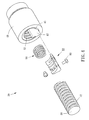
Conventional ball screw designs commonly have a circulating element arranged in the screw nut to provide a circulating passage for enabling balls to circulate between the screw shaft and the screw nut. FIG. 1 illustrates a prior art ball screw 10, which is characterized by the formation of a mounting groove 16 in the hole wall of an axial hole 15 of a screw nut 13 for accommodating a circulating element 17, which defines therein a circulating passage 18 that is connected to an internal thread groove 14 of a screw nut 13, thus, balls 19 can move through a circulating passage that is formed of an external thread groove 12 of a screw shaft 11, an internal thread groove 14 of a screw nut 13 and the circulating passage 18 of the circulating element 17. This type of circulating element 17 can be used only under the condition that the screw nut 13 has an external thread groove located on its one end and linked to the equipment, or the internal thread groove 14 of the screw nut 13 has a short pitch, or the screw nut 13 of the ball screw has a small outer diameter. Due to the structural limitations of the screw nut, the aforesaid prior art circulating element 17 cannot be replaced by a commonly known external circulating or end plug circulating type circulating element.
However, in the aforesaid prior art ball screw 10, the mounting groove 16 of the screw nut 13 is made by electrical discharge wire-cutting technology. Except the drawback of high processing cost, the mounting groove 16 will extend through the two opposite ends of the screw nut 13 after the processing. Thus, when mounting the circulating element 17 in the mounting groove 16, it is necessary to constantly adjust the position of the circulating element 17. If position deviation occurs, connection between the circulating passage 18 and the internal thread groove 14 may be unable to achieve, resulting in an alignment problem, as shown in FIG. 2. When an alignment problem occurs, the moving smoothness of the balls 19 will be affected. If the balls 19 do not move smoothly, they will continuously impact the circulating element 17, causing circulating element damage or ball damage.
On the other hand, when loading the balls 19, the balls 19 must be loaded by lots to match the position of the circulating passage 18, i.e., load a first lot of balls 19 in the external thread groove 12, the internal thread groove 14 and the first circulating passage 18 at first, and then load a second lot of balls 19 in the external thread groove 12, the internal thread groove 14 and the second circulating passage 18, and so on, until all of the balls 19 have been loaded in every circulating passage 18. This ball loading procedure is complicated.
In conclusion, the aforesaid prior art technique has the drawbacks of high processing costs, assembly difficulty, low alignment accuracy, and poor running smoothness.
SUMMARY OF THE INVENTION
The present invention has been accomplished under the circumstances in view. It is the main object of the present invention to provide a circulating element for ball screw, which enables the ball screw to have the advantages of low processing costs, ease of assembly, high alignment accuracy, and excellent running smoothness.
To achieve this and other objects of the present invention, a circulating element in accordance with the present invention comprises a first surface, and a second surface opposite to the first surface. The circulating element comprises a circulating passage located on the first surface. The circulating passage extends from one side of the first surface to the other side of the first surface, having a coupling mouth located on each of two opposite ends thereof. The second surface of the circulating element comprises a coupling groove disposed between the two coupling mouths of the circulating passage.
Preferably, the second surface of the circulating element curves inwardly in direction toward the second surface to fit the outer surface of a screw shaft of the ball screw. Further, the first surface of the circulating element defines two inclined planes inclining in reversed directions. One inclined plane of the circulating passage extends along the length of the circulating element to the other inclined plane. Thus, the balls of the ball screw can run in and out of the circulating passage smoothly.
Preferably, the circulating element comprises at least one mounting hole cut through the first surface and the second surface. By means of inserting one respective fastening member through the screw nut of the ball screw and then fastening the fastening member to one respective mounting hole of the circulating element, the circulating element and the screw nut are affixed together.
Other advantages and features of the present invention will be fully understood by reference to the following specification in conjunction with the accompanying drawings, in which like reference signs denote like components of structure.
BRIEF DESCRIPTION OF THE DRAWINGS
FIG. 1 is an exploded view of a ball screw according to the prior art.
FIG. 2 is a sectional view of a part of the prior art ball screw, illustrating the mounting relationship between the screw nut and the circulating element.
FIG. 3 is an oblique top elevational view of a ball screw in accordance with a first embodiment of the present invention.
FIG. 4 is an exploded view of the ball screw in accordance with the first embodiment of the present invention.
FIG. 5 is a sectional view of the screw nut of the ball screw in accordance with the first embodiment of the present invention.
FIG. 6 is an elevational view of a circulating element for ball screw in accordance with the first embodiment of the present invention.
FIG. 7 is an end view of the circulating element for ball screw in accordance with the first embodiment of the present invention.
FIG. 8 is a top view of the circulating element for ball screw in accordance with the first embodiment of the present invention.
FIG. 9 is a bottom view of the circulating element for ball screw in accordance with the first embodiment of the present invention.
FIG. 10 is a sectional elevation of the ball screw in accordance with the first embodiment of the present invention, illustrating the relationship between the internal thread groove of the screw nut and the coupling groove of the circulating element.
FIG. 11 is a sectional plain view of the ball screw in accordance with the first embodiment of the present invention, illustrating the relationship between the coupling groove of the circulating element and the external thread groove of the screw shaft.
FIG. 12 is a sectional plain view of the ball screw in accordance with the first embodiment of the present invention, illustrating the relationship between the external thread groove of the screw shaft/the internal thread groove of the screw nut and the circulating passage of the circulating element.
FIG. 13 is an exploded view of the ball screw in accordance with the first embodiment of the present invention.
FIG. 14 is an exploded view of the circulating element for ball screw in accordance with the first embodiment of the present invention.
FIG. 15 is an exploded view of the circulating element for ball screw in accordance with the first embodiment of the present invention.
FIG. 16 is an exploded view of an alternate form of the circulating element for ball screw in accordance with the first embodiment of the present invention.
FIG. 17 is an elevational view of a circulating element for ball screw in accordance with a second embodiment of the present invention.
FIG. 18 is an elevational view of a ball screw in accordance with the second embodiment of the present invention.
FIG. 19 is another elevational view of the circulating element for ball screw in accordance with a second embodiment of the present invention.
FIG. 20 is another exploded view of the ball screw in accordance with the second embodiment of the present invention.
DETAILED DESCRIPTION OF THE INVENTION
Referring to FIGS. 3 and 4, a ball screw 20 using a circulating element 60 in accordance with a first embodiment of the present invention is shown. The ball screw 20 comprises a screw shaft 30, a screw nut 40, and a plurality of balls 50. The screw shaft 30 comprises an external thread groove 32. The screw nut 40 comprises an axial hole 41, which receives the screw shaft 30 for allowing the screw nut 40 to be axially moved along the screw shaft 30, and a mounting groove 42 and an internal thread groove 43 formed in the hole wall of the axial hole 41 and abutted against each other. The mounting groove 42 extends from one end edge of the screw nut 40 axially along the extending direction of the axial hole 41. Further, the mounting groove 42 has one end thereof terminating in a bearing surface 44 (see FIGS. 5 and 11). The internal thread groove 43 corresponds to the external thread groove 32 of the screw shaft 30, defining with the external thread groove 32 a first passage 51 for the running of one ball 50 (see FIGS. 11 and 12). The screw nut 40 further comprises two through holes 45 disposed at two opposite sides relative to the mounting groove 42 (see FIG. 5).
Referring to FIG. 6, the circulating element 60 in accordance with the first embodiment of the present invention has a configuration fitting the mounting groove 42 of the screw nut 40 so that the circulating element 60 can be mounted in the mounting groove 42 of the screw nut 40 and stopped at the bearing surface 44 of the mounting groove 42 after mounting (see FIG. 11), achieving positioning.
As illustrated in FIGS. 6-9, the circulating element 60 comprises a first surface 61, and a second surface 62 opposite to the first surface 61. The second surface 62 curves smoothly inwardly in direction toward the first surface 61 to fit the outer surface of the screw shaft 30. The first surface 61 is divided into opposing first inclined plane 611 and second inclined plane 612. The first inclined plane 611 and the second inclined plane 612 extend in parallel to the tangential direction of the second surface 62, i.e. in parallel to the tangential direction of the screw shaft 30. Further, the first inclined plane 611 defines a first lateral side 613 and a second lateral side 614, and the second inclined plane 612 defines a third lateral side 615 and a fourth lateral side 616, wherein the first lateral side 613 of the first inclined plane 611 and the third lateral side 615 of the second inclined plane 612 are connected together by a first curved chamfer 617; the second lateral side 614 of the first inclined plane 611 and the fourth lateral side 616 of the second inclined plane 612 respectively provide a second curved chamfer and connected to the second surface 62.
Referring to FIGS. 9 and 12 again, the first surface 61 defines a circulating passage 63 for the passing of each ball 50. The circulating passage 63 extends from the second lateral side 614 of the first inclined plane 611 of the first surface 61 along the length of the circulating element 60 over the first curved chamfer 617 and then obliquely toward the fourth lateral side 616 of the second inclined plane 612 of the first surface 61, having two opposite open ends thereof respectively terminating in a respective coupling mouth 632. The two coupling mouths 632 at the two opposite ends of the circulating passage 63 respectively cut through the first surface 61 and the second surface 62 and are respectively connected to the first passage 51 so that each ball 50 can move through the circulating passage 63 into or out of the first passage 51.
Referring to FIGS. 8, 10 and 11 again, the second surface 62 defines two opposite coupling grooves 64 and two opposite guide blocks 65. The two coupling grooves 64 are disposed between the two coupling mouths 632 of the circulating passage 63 and adapted to connect the internal thread groove 43 of the screw nut 40 and face toward the external thread groove 32 of the screw shaft 30 such that a second passage 52 is defined between each coupling groove 64 and the external thread groove 32 and connected to the first passage 51 for the passing of each ball 50. The guide blocks 65 are received in the external thread groove 32, each having one end thereof protruding out of the corresponding coupling mouth 632 of the circulating passage 63 for guiding each ball 50 into the first passage 51. It is to be noted that each guide block 65 and the second surface 62 can be integrally made in one piece, or detachably arranged together. In this embodiment, the two guide blocks 65 are formed integral with the second surface 62. In the embodiment shown in FIG. 13, the two guide blocks 65 are respectively detachably joined to the second surface 62. It is to be noted that the use of the guide blocks 65 are not a limitation. Each ball 50 can still run into the first passage 51 without the guide blocks 65. However, the arrangement of the guide blocks 65 enhances running smoothness of the balls 50.
Further, the circulating element 60 comprises two opposite mounting holes 66 respectively cutting through the first surface 61 and the second surface 62 adjacent to the respective guide blocks 65 and in communication with the respective through holes 45 of the screw nut 40. During installation, two fastening members 80 (for example, screws) are respectively inserted through the through holes 45 of the screw nut 40 and fastened to the respective mounting holes 66 of the circulating element 60 to affix the screw nut 40 and the circulating element 60 together. Further, except the mounting method of using the fastening members (screws) 80, tongue and groove mating structure can be used as a substitute, for example, the screw nut 40 can be configured to provide a coupling groove, and the circulating element 60 can be configured to provide a coupling tongue that can be press-fitted into the coupling groove of the circulating element 60.
In conclusion, the circulating element 60 and the ball screw 20 in accordance with the present invention have the following advantages and features:
1. The mounting groove 42 of the screw nut 40 can be formed using a milling or drilling technique; the circulating element 60 can be made using a plastic injection molding or metal forming technique; there is no any particular limitation in this regard. After processing to form the mounting groove 42 on the screw nut 40, the bearing surface 44 is directly formed without cutting through the screw nut 40. Thus, when inserting the circulating element 60 into the mounting groove 42 during installation, the circulating element 60 can be stopped at the bearing surface 44 to achieve positioning without any further adjustment of the position of the circulating element 60. When compared to conventional techniques, the design of the present invention effectively reduces the processing costs, simplifies the installation procedure, and eliminates the problem of alignment between the circulating passage 63 and coupling groove 64 of the circulating element 60 and the internal thread groove 43 of the screw nut 40. In other words, the invention has the advantages of low processing costs, ease of installation and high alignment accuracy.
2. Every ball 50 runs in a circulating path formed of the first passage 51, the two second passages 52 and the circulating passage 63, wherein the entrance region and exit region of the circulating passage 63 are kept in parallel to the tangential direction of the screw shaft 30 subject to the inclined plane design of the first surface 61, enabling each ball 50 to run smoothly from the first passage 51 into the circulating passage 63 and also to run smoothly from the circulating passage 63 into the first passage 51, and therefore the invention significantly enhances the running smoothness of the balls. Further, all of the balls 50 can be loaded in one single loading step, eliminating the drawback of the prior art technique to load all of the balls by lots. After all of the balls 50 have been put in the first passage 51, each ball 50 can run along the first passage 51, the second passages 52 and the circulating passage 63 to fill up the whole circulating path, simplifying the ball loading process.
3. The use of one single circulating element 60 is not a limitation. Alternatively, two circulating elements 60 can be abutted against each other to fit the dimension of the screw nut 40. Further, the circulating element 60 can be a one-piece member. Alternatively, the circulating element 60 can be formed of two sub-bodies 68 longitudinally connected in line, as shown in FIGS. 14 and 15, or transversely connected in a parallel manner, as shown in FIG. 16. When the two sub-bodies 68 are connected together in either of the aforesaid two connection methods, the circulating element 60 achieves the same effects as the one-piece design.
Further, as shown in FIGS. 17-20, a circulating element 70 in accordance with a second embodiment of the present invention comprises a first surface 71, and a second surface 72 opposite to the first surface 71. The second surface 72 curves inwardly in direction toward the first surface 71 to fit the outer surface of the screw shaft 30. The first surface 71 defines a circulating passage 73 for the passing of the balls 50. The circulating passage 73 extends from one lateral side of the first surface 71 along the length of the circulating element 70 to the other lateral side of the first surface 71, having two opposite open ends thereof respectively terminating in a respective coupling mouth 732 that cut through the respective lateral side of the circulating element 70 for connection with the first passage 51. Thus, every ball 50 can run into and out of the first passage 51 through the circulating passage 73. The second surface 72 defines four coupling grooves 74. Each coupling groove 74 is disposed between the two coupling mouths 732 of the circulating passage 73 and adapted to connect the internal thread groove 43 of the screw nut 40, and also arranged to face toward the external thread groove 32 of the screw shaft 30. Thus, every ball 50 can run from each coupling mouth 732 along the circulating passage 73 into the circulating element 70, and then guided by the circulating passage 73 to return to the first passage 51 subject to the guide of.
Thus, during the ball loading operation, the structural design of the circulating passage 73 allows all of the balls 50 to be loaded in one step, eliminating the drawback of the prior art techniques to load all of the balls by lots and simplifying the ball loading process.
Although particular embodiments of the invention have been described in detail for purposes of illustration, various modifications and enhancements may be made without departing from the spirit and scope of the invention. Accordingly, the invention is not to be limited except as by the appended claims.

Claims (19)

What is claimed is:
1. A circulating element used in a ball screw having a screw shaft, said circulating element comprising:
a first surface and a second surface opposite to said first surface, said first surface comprising a circulating passage, said circulating passage extending through said first surface, and
two coupling mouths arranged respectively at two opposite ends of said circulating passage, said second surface comprising a coupling groove disposed between the two coupling mouths of said circulating passage;
wherein said first surface defines a first inclined plane and a second inclined plane, said first inclined plane and said second inclined plane inclining in reversed directions; and
wherein the first inclined plane and the second inclined plane extend in parallel to a tangential direction of the screw shaft.
2. The circulating element as claimed in claim 1, further comprising two guide blocks respectively protruding out of said two coupling mouths of said circulating passage.
3. The circulating element as claimed in claim 1, wherein said second surface curves in a direction toward said first surface.
4. The circulating element as claimed in claim 3, wherein said first inclined plane comprising a first lateral side and a second lateral side, said second inclined plane comprising a third lateral side and a fourth lateral side, said first lateral side of said first inclined plane and said third lateral side of said second inclined plane being connected together, said second lateral side of said first inclined plane and said fourth lateral side of said second inclined plane being respectively connected to said second surface; said circulating passage extends from said second lateral side of said first inclined plane along the length of the circulating element to said fourth lateral side of said second inclined plane.
5. The circulating element as claimed in claim 4, wherein said first surface further comprises a first curved chamfer connected between said first lateral side of said first inclined plane and said third lateral side of said second inclined plane.
6. The circulating element as claimed in claim 4, wherein said second lateral side of said first inclined plane and said fourth lateral side of said second inclined plane respectively provide a respective second curved chamfer.
7. The circulating element as claimed in claim 6, further comprising at least one mounting hole cut through said first surface and said second surface.
8. The circulating element as claimed in claim 1, wherein said circulating passage is an open passage.
9. The circulating element as claimed in claim 8, wherein each said coupling mouth cuts through said first surface and said second surface.
10. A ball screw, comprising:
a screw shaft comprising an external thread groove;
a screw nut comprising an axial hole for receiving said screw shaft, a mounting groove and an internal thread groove located on an inside wall of said axial hole and abutted against each other, said internal thread groove fitting said external thread groove of said screw shaft, said internal thread groove and said external thread groove defining a first passage therebetween; and
a circulating element configured subject to the configuration of said mounting groove of said screw nut and mounted in said mounting groove of said screw nut, said circulating element comprising a first surface and a second surface opposite to said first surface, said first surface comprising a circulating passage, said circulating passage extending through said first surface, said circulating element having two coupling mouths respectively at two opposite ends of said circulating passage, said second surface comprising a coupling groove disposed between the two coupling mouths of said circulating passage, the two coupling mouths of said circulating passage being respectively connected to said first passage, said coupling groove having two opposite ends thereof respectively connected to said internal thread groove, said coupling groove facing toward said external thread groove and defining with said external thread groove a second passage therebetween, said second passage having two opposite ends thereof respectively connected to said first passage; wherein said first surface defines a first inclined plane and a second inclined plane, said first inclined plane and said second inclined plane inclining in reversed directions;
wherein the first inclined plane and the second inclined plane extend in parallel to a tangential direction of the screw shaft; and
a plurality of balls rotatably accommodated in said first passage, said second passage and said circulating passage.
11. The ball screw as claimed in claim 10, further comprising two guide blocks respectively protruding out of said two coupling mouths of said circulating passage of said circulating element, each said guide block being received in said external thread groove.
12. The ball screw as claimed in claim 10, wherein said mounting groove extends from an end edge of said screw nut axially along said axial hole, having one end thereof terminating in a bearing surface for supporting one end of said circulating element.
13. The ball screw as claimed in claim 10, wherein said second surface of said circulating element curves in a direction toward said first surface and fitting the outer surface of said screw shaft.
14. The ball screw as claimed in claim 13, wherein said first inclined plane comprising a first lateral side and a second lateral side, said second inclined plane comprising a third lateral side and a fourth lateral side, said first lateral side of said first inclined plane and said third lateral side of said second inclined plane being connected together, said second lateral side of said first inclined plane and said fourth lateral side of said second inclined plane being respectively connected to said second surface; said circulating passage extends from said second lateral side of said first inclined plane along the length of the circulating element to said fourth lateral side of said second inclined plane.
15. The ball screw as claimed in claim 14, wherein said first surface further comprises a first curved chamfer connected between said first lateral side of said first inclined plane and said third lateral side of said second inclined plane.
16. The circulating element as claimed in claim 15, wherein said second lateral side of said first inclined plane and said fourth lateral side of said second inclined plane respectively provide a second curved chamfer connected to said second surface.
17. The circulating element as claimed in claim 16, wherein said screw nut comprises at least one through hole; said circulating element comprises at least one mounting hole cut through said first surface and said second surface and kept in communication with said at least one through hole of said screw nut and respectively fixedly connected to said at least one through hole of said screw nut by one respective fastening member.
18. The circulating element as claimed in claim 10, wherein said circulating passage is an open passage.
19. The circulating element as claimed in claim 18, wherein each said coupling mouth cuts through said first surface and said second surface.
US13/944,219 2012-12-28 2013-07-17 Circulating element for ball screw and ball screw using the circulating element Active 2033-09-22 US9091336B2 (en)

Applications Claiming Priority (3)

Application Number Priority Date Filing Date Title
TW101151250 2012-12-28
TW101151250A 2012-12-28

Publications (2)

Publication Number Publication Date
US20140182407A1 US20140182407A1 (en) 2014-07-03
US9091336B2 true US9091336B2 (en) 2015-07-28

Family

ID=50928560

Family Applications (1)

Application Number Title Priority Date Filing Date
US13/944,219 Active 2033-09-22 US9091336B2 (en) 2012-12-28 2013-07-17 Circulating element for ball screw and ball screw using the circulating element

Country Status (5)

Country Link
US (1) US9091336B2 (en)
JP (1) JP5837533B2 (en)
CN (1) CN103912648B (en)
DE (1) DE102013106814B4 (en)
TW (1) TWI509170B (en)

Cited By (3)

* Cited by examiner, † Cited by third party
Publication number Priority date Publication date Assignee Title
US20180216711A1 (en) * 2015-08-04 2018-08-02 Schaeffler Technologies AG & Co. KG Ball screw drive
US11015688B2 (en) 2015-08-04 2021-05-25 Schaeffler Technologies AG & Co. KG Ball screw drive
US11655885B2 (en) * 2019-12-06 2023-05-23 Pacific Bearing Corp. Multiliner for multiple start ball nut threads

Families Citing this family (4)

* Cited by examiner, † Cited by third party
Publication number Priority date Publication date Assignee Title
TWM502765U (en) * 2014-12-30 2015-06-11 Hiwin Tech Corp Circulating positioning structure for ball screw
KR200494263Y1 (en) * 2019-12-23 2021-09-06 하이윈 테크놀로지스 코포레이션 Internal recirculation type ball screw
JP7495969B2 (en) 2022-11-10 2024-06-05 上銀科技股▲分▼有限公司 Internal Circulation Ball Screw
DE102022130564B4 (en) 2022-11-18 2024-09-26 Hiwin Technologies Corp. BALL SCREW WITH INTERNAL BALL CIRCULATION

Citations (7)

* Cited by examiner, † Cited by third party
Publication number Priority date Publication date Assignee Title
US2519777A (en) * 1946-01-18 1950-08-22 Cochrane Alfred Paul Mill Worm and nut mechanism
US3327551A (en) * 1965-03-12 1967-06-27 Gen Motors Corp Ball return means for ball nut and screw means
US3942846A (en) * 1973-11-30 1976-03-09 Richard Wilke Ball race
US4841796A (en) * 1986-05-19 1989-06-27 Hiroshi Teramachi Ball screw having an axially extending ball deflector
US6112610A (en) * 1997-08-05 2000-09-05 Thomson Saginaw Ball Screw Company, Llc Externally insertable self-retaining crossover for ball nut and screw assemblies
US20020003059A1 (en) * 2000-03-04 2002-01-10 Morihisa Yoshioka Ball screw mechanism and electrically powered steering device utilizing the same
US20070295132A1 (en) * 2006-04-13 2007-12-27 Hiwin Technologiescorp. Guiding device for ball nut

Family Cites Families (18)

* Cited by examiner, † Cited by third party
Publication number Priority date Publication date Assignee Title
US3261224A (en) * 1964-01-27 1966-07-19 Specialties Dev Corp Nut for ball screw and nut assembly
JPS4519526Y1 (en) * 1965-09-08 1970-08-07
GB1094350A (en) * 1966-11-11 1967-12-06 Scully Jones Company Improved ball screw mechanism
JPS4833489Y1 (en) * 1971-10-19 1973-10-11
JPS50114583U (en) * 1974-03-05 1975-09-18
DE3244508A1 (en) * 1982-12-02 1984-06-07 A. Mannesmann Maschinenfabrik Gmbh & Co Kg, 5630 Remscheid BALL SCREW DRIVE
DE3628802A1 (en) * 1986-08-25 1988-03-03 Deckel Ag Friedrich BALL RETURN
DE8809239U1 (en) * 1988-07-19 1988-09-15 Isert, Hugo, 6419 Eiterfeld Ball screw drive
US6813969B2 (en) * 2002-07-01 2004-11-09 Delphi Technologies, Inc. Rocker return liner for ball nut
TWM275321U (en) * 2005-02-02 2005-09-11 Mau-Duen Li Improve inner circulator structure of ball screw
WO2007063696A1 (en) * 2005-11-30 2007-06-07 Thk Co., Ltd. Rolling screw device
TWI262268B (en) * 2006-01-27 2006-09-21 Hiwin Tech Corp Guiding and positioning device for screw shaft
JP3122121U (en) * 2006-03-22 2006-06-01 上銀科技股▲ふん▼有限公司 Stereo structure of ball screw circulation block
TWM308347U (en) * 2006-07-28 2007-03-21 Comtop Technology Co Ltd Return structure of ball nut
TWI319468B (en) * 2007-09-12 2010-01-11 Hiwin Tech Corp External circulation type ball screw
CN101126437A (en) * 2007-09-14 2008-02-20 李敬宇 Ball guide-screw pair
JP2009103201A (en) * 2007-10-23 2009-05-14 Shangyin Sci & Technol Co Ltd Outside circulation type ball screw
CN202468888U (en) * 2011-12-27 2012-10-03 上银科技股份有限公司 Positioning structure of reflow assembly of ball screw

Patent Citations (7)

* Cited by examiner, † Cited by third party
Publication number Priority date Publication date Assignee Title
US2519777A (en) * 1946-01-18 1950-08-22 Cochrane Alfred Paul Mill Worm and nut mechanism
US3327551A (en) * 1965-03-12 1967-06-27 Gen Motors Corp Ball return means for ball nut and screw means
US3942846A (en) * 1973-11-30 1976-03-09 Richard Wilke Ball race
US4841796A (en) * 1986-05-19 1989-06-27 Hiroshi Teramachi Ball screw having an axially extending ball deflector
US6112610A (en) * 1997-08-05 2000-09-05 Thomson Saginaw Ball Screw Company, Llc Externally insertable self-retaining crossover for ball nut and screw assemblies
US20020003059A1 (en) * 2000-03-04 2002-01-10 Morihisa Yoshioka Ball screw mechanism and electrically powered steering device utilizing the same
US20070295132A1 (en) * 2006-04-13 2007-12-27 Hiwin Technologiescorp. Guiding device for ball nut

Cited By (4)

* Cited by examiner, † Cited by third party
Publication number Priority date Publication date Assignee Title
US20180216711A1 (en) * 2015-08-04 2018-08-02 Schaeffler Technologies AG & Co. KG Ball screw drive
US10968992B2 (en) * 2015-08-04 2021-04-06 Schaeffler Technologies AG & Co. KG Ball screw drive
US11015688B2 (en) 2015-08-04 2021-05-25 Schaeffler Technologies AG & Co. KG Ball screw drive
US11655885B2 (en) * 2019-12-06 2023-05-23 Pacific Bearing Corp. Multiliner for multiple start ball nut threads

Also Published As

Publication number Publication date
TW201425772A (en) 2014-07-01
JP5837533B2 (en) 2015-12-24
JP2014129870A (en) 2014-07-10
DE102013106814B4 (en) 2016-04-28
TWI509170B (en) 2015-11-21
US20140182407A1 (en) 2014-07-03
DE102013106814A1 (en) 2014-07-03
CN103912648A (en) 2014-07-09
CN103912648B (en) 2016-04-06

Similar Documents

Publication Publication Date Title
US9091336B2 (en) Circulating element for ball screw and ball screw using the circulating element
US20090013811A1 (en) External Circulation Type Ball Screw
US7350434B2 (en) Ball screw device
US7487692B2 (en) Guiding device for ball nut
US20100170360A1 (en) Deflecting device for ball screw device
KR20020038528A (en) Guide Apparatus
KR20170024117A (en) Ball screw
CN101903686B (en) Roller screw
US20070009188A1 (en) Linear guide apparatus
KR20200003504A (en) External circulation ball screw
US20120192667A1 (en) Ball screw with a circulating assembly
TWI651478B (en) Ball screw
KR20170026252A (en) Fastening system for a machine element
US8640564B2 (en) Circulation element for ball screw
US20070221002A1 (en) Roller screw mechanism
US8011832B2 (en) Linear guide
US20140224052A1 (en) Circulating device for motion guide apparatus
US9297415B2 (en) Linear actuator
US20220205482A1 (en) Linear motion device
US9388889B2 (en) Deflecting device for motion guide apparatus
US7578214B2 (en) Preload structure for a ball screw
EP2514998B1 (en) Ball screw assembly with recirculating cap
CN110541917B (en) External circulation type ball screw
US7134790B2 (en) Recirculating apparatus of linear motion guiding
JP2005083520A (en) Ball screw device

Legal Events

Date Code Title Description
AS Assignment

Owner name: HIWIN TECHNOLOGIES CORP., TAIWAN

Free format text: ASSIGNMENT OF ASSIGNORS INTEREST;ASSIGNORS:LIN, MING-YAO;KUO, MING-CHE;REEL/FRAME:030817/0815

Effective date: 20130624

STCF Information on status: patent grant

Free format text: PATENTED CASE

MAFP Maintenance fee payment

Free format text: PAYMENT OF MAINTENANCE FEE, 4TH YEAR, LARGE ENTITY (ORIGINAL EVENT CODE: M1551); ENTITY STATUS OF PATENT OWNER: LARGE ENTITY

Year of fee payment: 4

MAFP Maintenance fee payment

Free format text: PAYMENT OF MAINTENANCE FEE, 8TH YEAR, LARGE ENTITY (ORIGINAL EVENT CODE: M1552); ENTITY STATUS OF PATENT OWNER: LARGE ENTITY

Year of fee payment: 8