US9080746B2 - LED assembly having a refractor that provides improved light control - Google Patents
LED assembly having a refractor that provides improved light control Download PDFInfo
- Publication number
- US9080746B2 US9080746B2 US13/837,731 US201313837731A US9080746B2 US 9080746 B2 US9080746 B2 US 9080746B2 US 201313837731 A US201313837731 A US 201313837731A US 9080746 B2 US9080746 B2 US 9080746B2
- Authority
- US
- United States
- Prior art keywords
- light
- lens
- optical element
- preferred
- emitter
- Prior art date
- Legal status (The legal status is an assumption and is not a legal conclusion. Google has not performed a legal analysis and makes no representation as to the accuracy of the status listed.)
- Active
Links
Images


Classifications
-
- F—MECHANICAL ENGINEERING; LIGHTING; HEATING; WEAPONS; BLASTING
- F21—LIGHTING
- F21V—FUNCTIONAL FEATURES OR DETAILS OF LIGHTING DEVICES OR SYSTEMS THEREOF; STRUCTURAL COMBINATIONS OF LIGHTING DEVICES WITH OTHER ARTICLES, NOT OTHERWISE PROVIDED FOR
- F21V13/00—Producing particular characteristics or distribution of the light emitted by means of a combination of elements specified in two or more of main groups F21V1/00 - F21V11/00
- F21V13/02—Combinations of only two kinds of elements
- F21V13/04—Combinations of only two kinds of elements the elements being reflectors and refractors
-
- F—MECHANICAL ENGINEERING; LIGHTING; HEATING; WEAPONS; BLASTING
- F21—LIGHTING
- F21V—FUNCTIONAL FEATURES OR DETAILS OF LIGHTING DEVICES OR SYSTEMS THEREOF; STRUCTURAL COMBINATIONS OF LIGHTING DEVICES WITH OTHER ARTICLES, NOT OTHERWISE PROVIDED FOR
- F21V5/00—Refractors for light sources
- F21V5/04—Refractors for light sources of lens shape
-
- F—MECHANICAL ENGINEERING; LIGHTING; HEATING; WEAPONS; BLASTING
- F21—LIGHTING
- F21V—FUNCTIONAL FEATURES OR DETAILS OF LIGHTING DEVICES OR SYSTEMS THEREOF; STRUCTURAL COMBINATIONS OF LIGHTING DEVICES WITH OTHER ARTICLES, NOT OTHERWISE PROVIDED FOR
- F21V5/00—Refractors for light sources
- F21V5/08—Refractors for light sources producing an asymmetric light distribution
-
- F—MECHANICAL ENGINEERING; LIGHTING; HEATING; WEAPONS; BLASTING
- F21—LIGHTING
- F21W—INDEXING SCHEME ASSOCIATED WITH SUBCLASSES F21K, F21L, F21S and F21V, RELATING TO USES OR APPLICATIONS OF LIGHTING DEVICES OR SYSTEMS
- F21W2131/00—Use or application of lighting devices or systems not provided for in codes F21W2102/00-F21W2121/00
- F21W2131/10—Outdoor lighting
-
- F21Y2101/02—
-
- F—MECHANICAL ENGINEERING; LIGHTING; HEATING; WEAPONS; BLASTING
- F21—LIGHTING
- F21Y—INDEXING SCHEME ASSOCIATED WITH SUBCLASSES F21K, F21L, F21S and F21V, RELATING TO THE FORM OR THE KIND OF THE LIGHT SOURCES OR OF THE COLOUR OF THE LIGHT EMITTED
- F21Y2115/00—Light-generating elements of semiconductor light sources
- F21Y2115/10—Light-emitting diodes [LED]
Definitions
- LEDs Light emitting diodes
- LEDs are used in a variety of general lighting applications such as streetlights, parking garage lighting, and parking lots. LEDs have reached efficiency values per watt that outpace almost all traditional light sources. LEDs, however, can be expensive in lumens per dollar compared to light sources. Because of the high cost of using LEDs, optical, electronic and thermal efficiencies can be very important. In direction lighting applications, such as street lighting, it is inefficient to illuminate the house side of the street rather than direct all the light toward the street. Total internal reflection (TIR) lenses have been used to successfully direct house-side light toward the street. But these TIR solutions are still not very efficient.
- TIR Total internal reflection
- Embodiments of the invention include an LED assembly that includes optics and optical arrangements for light emitting diodes (LEDs).
- a reflector is provided within a void between the lens and the LED. This reflector can reflect light emitted by the LED in a non-preferred direction back toward the preferred direction.
- an optical element is formed or otherwise provided in the lens cavity and shaped so that, when the lens is positioned above the LED, the refractor bends the emitted light in a preferred direction.
- both a reflector and optical element are provided in the LED assembly to control the directionality of the emitted light. Such embodiments of the invention can be used to increase the efficiency of an LED by ensuring that generated light is being directed to the target area of choice.
- FIG. 1 shows a cross-section of one embodiment of an LED assembly.
- FIG. 2 shows another cross-section of the LED assembly of FIG. 1 .
- FIG. 3 shows a cross-section of an alternative embodiment of an LED assembly.
- FIG. 4 shows a cross-section of yet another alternative embodiment of an LED assembly.
- FIG. 5 shows a cross-section of still another alternative embodiment of an LED assembly.
- FIG. 6 shows a cross-section of yet another alternative embodiment of an LED assembly.
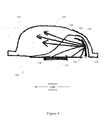
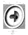
- FIG. 7 shows a bottom perspective view of one embodiment of a lens for use in an embodiment of an LED assembly.
- FIG. 11 is a bottom perspective view of an embodiment of an optical element in isolation.
- FIG. 12 is a cross-sectional view of the lens of FIG. 7 positioned over a light emitter.
- FIG. 13 is a cross-sectional view of an alternative embodiment of an LED assembly that includes the lens of FIG. 7 and a reflector.
- FIG. 14 is a bottom perspective view of the lens and reflector shown in FIG. 13 .
- Embodiments of the invention include an LED assembly that includes optics and optical arrangements for light emitting diodes (LEDs).
- a reflector is provided within a void between the lens and the LED. This reflector can reflect light emitted by the LED in a non-preferred direction back toward the preferred direction.
- an optical element is formed or otherwise provided in the lens cavity and shaped so that, when the lens is positioned above the LED, the refractor bends the emitted light in a preferred direction.
- both a reflector and optical element are provided in the LED assembly to control the directionality of the emitted light. Such embodiments of the invention can be used to increase the efficiency of an LED by ensuring that generated light is being directed to the target area of choice.
- FIG. 1 shows a top view of an LED assembly 100 cut along line A-A of the cross-sectional view of LED assembly 100 shown in FIG. 2 .
- LED assembly 100 can include light emitter 115 disposed within lens 105 such that a void 110 exists between the lens 105 and light emitter 115 and surrounds light emitter 115 .
- void 110 can be semi-hemispherical, but void 110 is certainly not intended to be limited to this geometry. Rather, the inner surface 108 of the lens 105 , and thus the shape of void 110 dictated by such inner surface 108 , can be of any desired shape. For example, FIG.
- FIG. 3 illustrates another embodiment of the LED assembly 100 where the inner surface 108 of the lens 105 is not semi-hemispherical.
- FIG. 4 illustrates a cross-section of another embodiment of LED assembly 100 where the inner surface 108 of lens 105 is shaped so as to create a thick lens portion 112 .
- Light emitter 115 can be any type of light emitter known in the art.
- light emitter 115 can include a light emitter made from Aluminum gallium arsenide (AlGaAs), Gallium arsenide phosphide (GaAsP), Aluminum gallium indium phosphide (AlGaInP), Gallium(III) phosphide (GaP), Aluminum gallium phosphide (AlGaP), Zinc selenide (ZnSe), Indium gallium nitride (InGaN), Silicon carbide (SiC) Silicon (Si), or Indium gallium nitride (InGaN).
- AlGaAs Aluminum gallium arsenide
- GaAsP Gallium arsenide phosphide
- AlGaInP Aluminum gallium indium phosphide
- GaP Gallium(III) phosphide
- AlGaP Aluminum gallium phosphide
- Zinc selenide Zin
- lens 105 can include plastic, glass, silicon, epoxy, or acrylic material. These materials may or may not be optical grade.
- Embodiments of LED assembly 100 includes reflector 120 that is positioned within the void 110 so as to extend at least partially around the light emitter 115 .
- Retention structure such as tab 122
- the reflector 120 may include more than one tab 122 (see FIG. 5 ) or the tab may be a continuous tab that extends all the way or partially around the base of reflector 120 , as shown in FIG. 6 .
- the tab 122 can have any geometry that permits it to attach the reflector 120 to the circuit board 130 .
- any retention structure that permits the reflector 120 to be attached to the circuit board 130 may be used and certainly is not limited to the tab geometry disclosed herein.
- Tab 122 can be secured to circuit board 130 using any attachment scheme, for example, using solder, a screw, staple, glue, adhesive, heat bonding, rivets, push tab connectors, slot tab connectors, etc.
- reflector 120 can be coupled directly with the top surface of circuit board 130 . Using these tabs 122 , the reflector 120 is secured directly to circuit board 130 and not to lens 105 . In some embodiments, for example, reflector 120 may not be in contact with lens 105 .
- reflector 120 can be secured to the circuit board using a light emitter holder (e.g., an LED COB array holder).
- a light emitter holder can be used to secure an LED to a circuit board or a substrate. Some LEDs are powered with contacts that are not soldered to a circuit board. Instead, a light emitter holder can be screwed to the circuit board in such a way to hold and secure the light emitter in place on the circuit board and to keep the necessary electrical contacts in place.
- a light emitter holder can be used to secure the reflector to the circuit board.
- the reflector can include tab 122 with a hole that is sized to correspond with the screw (or bolt) that secures light emitter holder into place.
- Tab 122 can be secured to the circuit board using the same screw that secures the light emitter holder. This screw can pass through the hole in tab 122 .
- Reflector 120 can be placed above or beneath light emitter holder. In some embodiments, reflector 120 can pressed to the circuit board with the light emitter holder with or without the screw passing through tab 122 .
- Reflector 120 can have shape and/or dimension (e.g., height) that permits the reflector 120 to fit within void 110 .
- the reflector 120 has a semi-circular shape so as to curve around light emitter 115 and azimuthally surround light emitter 115 around 180°.
- reflector 120 can azimuthally surround light emitter 115 around 270°, 225°, 135°, 90°, etc.
- the reflector 120 is not limited to the illustrated semi-circular shape but rather can have any desired shape, including semi-oval or elliptical cross sectional shapes.
- reflector 120 may include a continuous curve that wraps around light emitter 115 .
- FIG. 1 illustrates the reflector 120 as having a consistent cross-sectional shape (i.e., an inner surface 126 and an outer surface 124 of the same shape), it need not. Rather, the inner surface 126 and outer surface 124 can be of different shapes.
- the inner surface 126 of the reflector 120 can be of any shape that effectuates the desired reflection of light in a preferred light direction, as discussed below. This includes, but is not limited to, an inner surface 126 having an elliptical, parabolic shape or irregular geometry.
- reflector 120 can comprise a plurality of reflectors.
- reflector 120 does not only extend around the light emitter 115 but rather can also extend partially over the light emitter 115 so as to reflect nearly vertical light emitted by the light emitter 115 .
- the reflector 120 may be formed of any suitable material, including polymeric materials (e.g., optical grade polyesters, polycarbonates, acrylics, etc.) or metallic materials (e.g., prefinished anodized aluminum (e.g. Alanod Miro), prefinished anodized silver (e.g. Alanod Miro Silver), painted steel or aluminum, etc.).
- the inner surface 126 of the reflector should have a high surface reflectivity, preferably, but not necessarily, between 96%-100%, inclusive, and more preferably 98.5-100%, inclusive.
- Reflector 120 is shaped and positioned relative to light emitter 115 to direct light from the light emitter 115 in a desired or preferred direction.
- light emitted from light emitter 115 in a non-preferred direction impinges upon the inner surface 126 of reflector 120 , which in turn reflects the light in the preferred direction.
- light ray(s) 150 exits light emitter 115 , hits the inner surface 126 of reflector 120 , and is reflected back in the preferred light direction (as viewed from above).
- the positioning of the reflector 120 within void 110 and the shape of the inner surface 126 of the reflector 120 can be controlled to achieve the desired directionality of the reflected light.
- thick lens portion 112 may be dictated, for example, by the desired outward surface shape and/or any refracting requirements.
- FIG. 7 shows the underside of lens 300 according to some embodiments of the invention.
- Lens 300 includes an outer surface and inner surface 305 that defines a lens cavity 308 .
- the lens cavity 308 can be formed so as to control the directionality of the light emitted from the lens 300 .
- the lens cavity 308 includes a preferred-side void 310 and non-preferred-side void 315 .
- Each void 310 , 315 can be of any shape and is certainly not limited to the geometries shown in the Figures.
- Non-preferred-side void 315 can have a semi-hemispherical cross-sectional shape or a semi-ovoid cross-sectional shape.
- Preferred-side void 310 can also have a semi-hemispherical cross-sectional shape or a semi-ovoid cross-sectional shape.
- Preferred-side void 310 can also have some linear portions or parabolic portions.
- the two voids 310 and 315 can be cut, etched, or molded into lens 300 .
- Lens 300 can be positioned over a light emitter or other light source.
- the light emitter can be centrally disposed between the two voids 310 and 315 .
- the light emitter can be positioned in one or the other void 310 or 315 .
- An optical element 320 may also be provided in the lens cavity 308 .
- the optical element 320 may be a separate component that is attached to the lens 300 within the lens cavity 308 or alternatively may be shaped when forming the lens cavity 308 .
- the optical element 320 may have any desired shape not inconsistent with the objectives of the present invention to capture and direct light in a preferred light direction.
- FIGS. 8 , 8 A, 9 , 9 A, 10 and 10 A illustrate in isolation various non-limiting shape geometries that optical element 320 may assume according to some embodiments.
- the optical element 320 may include a conical shape with a tapered side and smooth distal tip ( FIGS. 8 and 8A ), a conical shape with a tapered side and pointed distal tip ( FIGS. 9 and 9A ) or a modified hourglass shape ( FIGS. 10 and 10A ).
- the optical element 320 need not, and often will not, include the entirety of a shape geometry, such as those shown in FIGS. 8-10 .
- FIG. 7 shows an embodiment of a lens 300 having an optical element 320 provided in the lens cavity 308
- FIG. 11 shows the optical element 320 of FIG. 7 in isolation.
- the optical element 320 of FIG. 11 has a substantially conical shape with an upper plane 425 , a flat side wall 435 , and a curved side wall 428 that tapers downwardly from the upper plane 425 into a distal tip 430 .
- Axis 415 extends through tip 430 .
- Optical element 320 of FIG. 11 is similar to the shape of FIG. 7 if such shape was sliced longitudinally down the middle (thereby creating flat side wall 435 ). Again, however, the optical element 320 may be of any shape and/or dimension.
- upper plane 425 can azimuthally circumscribe a semi-circle or circle around axis 415 .
- Upper plane 425 may also include an ellipse or semi-ellipse with axis 415 extending through one foci of the ellipse or through the center of the ellipse.
- At least one surface of the optical element 320 may be reflective.
- such surface may have a surface reflectivity between 90%-99.5%, inclusive; possibly 93%-96%, inclusive; and more preferably 98.5%-99%, inclusive.
- Such reflectivity may be achieved by forming the optical element 320 from a highly reflective material or alternatively treating the surface of the optical element 320 so as to achieve such reflectivity.
- optical element 320 extends downwardly into the lens cavity 308 .
- axis 415 can be parallel with the axis of the light emitter and/or lens 305 . In other embodiments, axis 415 and the light emitter axis can be the same axis and/or lens 305 .
- optical element 320 may reside in the non-preferred-side void 315 (as shown in FIG. 7 ) so as to be available to redirect light emitted into the non-preferred-side void 315 , as discussed below.
- the flat side wall 435 of optical element 320 abuts the plane 312 that separates non-preferred-side void 315 and preferred-side void 310 .
- optical element 320 can direct light from a light source (e.g., LED) that is emitted into the non-preferred direction (i.e., in the non-preferred-side void 315 ) back toward the preferred light direction.
- Light emitter 505 can produce light following light rays 510 and 515 . These light rays can pass through lens 300 . In particular, these light rays pass through optical element 320 .
- Light rays 510 and 515 are originally directed into non-preferred-side void 315 but impinge optical element 320 that, in turn, refracts light rays 510 and 515 so that they exit lens 300 in the preferred direction.
- FIG. 13 shows ray traces from a light emitter 505 emitted through lens 300 having both optical element 320 and reflector 120 , according to some embodiments of the invention.
- light ray 605 is reflected off reflector 120 and is refracted via optical element 320 .
- the combined reflection and refraction directs the light in the preferred light direction.
- reflector 120 is attached directly to a circuit board and is not supported by the lens.
- Light rays 610 and 615 are refracted through lens 300 in the preferred light direction. Light ray 615 enters preferred-side void 310 prior to being refracted through lens 300 . Light ray 610 is reflected off of reflector 120 , enters preferred-side void 310 , and exits after being refracted through lens 300 .
- FIG. 14 shows an embodiment of a lens 700 having curved reflector 120 and optical element 320 disposed within non-preferred-side void 315 .
- Light may pass through either preferred side void 310 or optical element 320 , depending on the longitudinal angle of incident on reflector 120 .
- high angle light relative to the vertical axis of light emitter 505
- Low angle light will reflect off reflector 120 and exit through optical element 320 .
Abstract
Description
Claims (18)
Priority Applications (5)
| Application Number | Priority Date | Filing Date | Title |
|---|---|---|---|
| US13/837,731 US9080746B2 (en) | 2013-03-15 | 2013-03-15 | LED assembly having a refractor that provides improved light control |
| EP14765038.6A EP2971945B1 (en) | 2013-03-15 | 2014-03-17 | Led assembly having a reflector or refractor that provides improved light control |
| PCT/US2014/030628 WO2014145802A2 (en) | 2013-03-15 | 2014-03-17 | Led assembly having a reflector or refractor that provides improved light control |
| CA2904368A CA2904368C (en) | 2013-03-15 | 2014-03-17 | Refractive light assemblies |
| US14/693,193 US9587802B2 (en) | 2013-03-15 | 2015-04-22 | LED assembly having a refractor that provides improved light control |
Applications Claiming Priority (1)
| Application Number | Priority Date | Filing Date | Title |
|---|---|---|---|
| US13/837,731 US9080746B2 (en) | 2013-03-15 | 2013-03-15 | LED assembly having a refractor that provides improved light control |
Related Child Applications (1)
| Application Number | Title | Priority Date | Filing Date |
|---|---|---|---|
| US14/693,193 Continuation US9587802B2 (en) | 2013-03-15 | 2015-04-22 | LED assembly having a refractor that provides improved light control |
Publications (2)
| Publication Number | Publication Date |
|---|---|
| US20140268811A1 US20140268811A1 (en) | 2014-09-18 |
| US9080746B2 true US9080746B2 (en) | 2015-07-14 |
Family
ID=51526330
Family Applications (2)
| Application Number | Title | Priority Date | Filing Date |
|---|---|---|---|
| US13/837,731 Active US9080746B2 (en) | 2013-03-15 | 2013-03-15 | LED assembly having a refractor that provides improved light control |
| US14/693,193 Active US9587802B2 (en) | 2013-03-15 | 2015-04-22 | LED assembly having a refractor that provides improved light control |
Family Applications After (1)
| Application Number | Title | Priority Date | Filing Date |
|---|---|---|---|
| US14/693,193 Active US9587802B2 (en) | 2013-03-15 | 2015-04-22 | LED assembly having a refractor that provides improved light control |
Country Status (1)
| Country | Link |
|---|---|
| US (2) | US9080746B2 (en) |
Cited By (5)
| Publication number | Priority date | Publication date | Assignee | Title |
|---|---|---|---|---|
| US9587802B2 (en) | 2013-03-15 | 2017-03-07 | Abl Ip Holding Llc | LED assembly having a refractor that provides improved light control |
| US9903561B1 (en) | 2015-11-09 | 2018-02-27 | Abl Ip Holding Llc | Asymmetric vision enhancement optics, luminaires providing asymmetric light distributions and associated methods |
| RU186640U1 (en) * | 2017-01-25 | 2019-01-28 | Ледил Ой | OPTICAL DEVICE FOR MODIFICATION OF LIGHT DISTRIBUTION SCHEME |
| US10274159B2 (en) | 2017-07-07 | 2019-04-30 | RAB Lighting Inc. | Lenses and methods for directing light toward a side of a luminaire |
| US20230032844A1 (en) * | 2021-07-28 | 2023-02-02 | Goodrich Lighting Systems GmbH & Co. KG | Exterior aircraft light and aircraft comprising the same |
Families Citing this family (3)
| Publication number | Priority date | Publication date | Assignee | Title |
|---|---|---|---|---|
| KR101665760B1 (en) * | 2014-05-12 | 2016-10-24 | 엘지전자 주식회사 | Light emitting module and lighting apparatus having the same |
| WO2016062927A1 (en) * | 2014-10-23 | 2016-04-28 | Creaopto Oü | Lighting apparatus and transmissive element for the same |
| CN210860730U (en) * | 2019-12-27 | 2020-06-26 | 苏州欧普照明有限公司 | Light source module and lamp |
Citations (57)
| Publication number | Priority date | Publication date | Assignee | Title |
|---|---|---|---|---|
| US1551274A (en) | 1925-08-25 | Highway-lighting unix | ||
| US2170912A (en) | 1936-07-28 | 1939-08-29 | Holophane Co Inc | Luminaire |
| US2662165A (en) | 1950-11-29 | 1953-12-08 | Holophane Co Inc | Yard and street lighting system and luminaires for use therein |
| US3191022A (en) | 1962-03-01 | 1965-06-22 | Holophane Co Inc | Luminaire |
| US3278743A (en) | 1963-12-16 | 1966-10-11 | Holophane Co Inc | Street light refractor |
| US3283140A (en) | 1955-10-24 | 1966-11-01 | Gen Electric | Street luminaire |
| US3340393A (en) | 1964-11-19 | 1967-09-05 | Holophane Co Inc | Underpass luminaire |
| US3459936A (en) | 1966-04-25 | 1969-08-05 | Holophane Co Inc | Luminaire fixture |
| US3524051A (en) | 1968-08-19 | 1970-08-11 | Gen Electric | Luminaire |
| US3679889A (en) | 1969-11-18 | 1972-07-25 | Holophane Co Inc | Bi-directional highway luminaire |
| US3766375A (en) | 1971-11-29 | 1973-10-16 | Holophane Co Inc | Interchange and area lighting luminaire |
| US4085318A (en) | 1974-04-22 | 1978-04-18 | Johns-Manville Corporation | Luminaire and luminaire reflector for use in an off-the roadway lighting arrangement |
| US4451875A (en) | 1982-03-02 | 1984-05-29 | Manville Service Corporation | Poster panel lighting fixture |
| US5130761A (en) | 1990-07-17 | 1992-07-14 | Kabushiki Kaisha Toshiba | Led array with reflector and printed circuit board |
| US5481445A (en) | 1994-02-15 | 1996-01-02 | Lexalite International Corp. | Transflection reflector having controlled reflected and transmitted light distribution |
| US5929788A (en) | 1997-12-30 | 1999-07-27 | Star Headlight & Lantern Co. | Warning beacon |
| US6095663A (en) | 1997-07-02 | 2000-08-01 | Truck-Lite Co., Inc. | Combination clearance and marker light assembly |
| US20030063476A1 (en) | 2001-09-28 | 2003-04-03 | English George J. | Replaceable LED lamp capsule |
| JP2004288866A (en) | 2003-03-20 | 2004-10-14 | Koha Co Ltd | Led lamp |
| US6971772B1 (en) | 2003-06-12 | 2005-12-06 | Acuity Brands, Inc. | Luminaire globes having internal light control elements |
| US20060072314A1 (en) | 2004-09-29 | 2006-04-06 | Advanced Optical Technologies, Llc | Optical system using LED coupled with phosphor-doped reflective materials |
| US7055996B2 (en) | 2002-03-19 | 2006-06-06 | Truck-Lite Co., Inc. | Side turn/marker lamp |
| US20070019416A1 (en) | 2005-07-19 | 2007-01-25 | Samsung Electro-Mechanics Co., Ltd. | Light emitting diode package having dual lens structure for lateral light emission |
| US7245203B2 (en) | 2004-04-01 | 2007-07-17 | Grote Industries, Inc. | Indicator apparatus and method for a vehicle using side-emitting light-emitting diode |
| US20070242441A1 (en) | 2006-04-14 | 2007-10-18 | Renaissance Lighting, Inc. | Dual LED board layout for lighting systems |
| US20070284592A1 (en) | 2006-06-12 | 2007-12-13 | Haase Michael A | Led device with re-emitting semiconductor construction and reflector |
| US7347586B2 (en) | 2005-05-09 | 2008-03-25 | Gamasonic Ltd. | LED light bulb |
| US20080239722A1 (en) * | 2007-04-02 | 2008-10-02 | Ruud Lighting, Inc. | Light-Directing LED Apparatus |
| US7445362B2 (en) | 2006-03-03 | 2008-11-04 | Hubbell Incorporated | Parking garage luminaire with interchangeable reflector modules |
| US7445359B2 (en) | 2006-12-15 | 2008-11-04 | Hon Hai Precision Industry Co., Ltd. | Optical lens and light emitting diode using the same |
| US7566911B2 (en) | 2004-12-28 | 2009-07-28 | Sharp Kabushiki Kaisha | Light-emitting diode lamp and light-emitting diode display device |
| US20090225551A1 (en) | 2008-03-07 | 2009-09-10 | Industrial Technology Research Institute | Illumination apparatus |
| US20090295266A1 (en) | 2008-05-27 | 2009-12-03 | Ramer David P | Solid state lighting using light transmissive solid in or forming optical integrating volume |
| US20090316384A1 (en) | 2007-01-12 | 2009-12-24 | Panasonic Corporation | Light-emitting device and illumination apparatus using the same |
| US20100014290A1 (en) * | 2008-07-15 | 2010-01-21 | Ruud Lighting, Inc. | Light-directing apparatus with protected reflector-shield and lighting fixture utilizing same |
| US20100033985A1 (en) | 2008-08-11 | 2010-02-11 | Jih-Tao Hsu | LED Luminescent Device and Vehicle Lamp Comprising the Device |
| US20100039810A1 (en) * | 2008-08-14 | 2010-02-18 | Cooper Technologies Company | LED Devices for Offset Wide Beam Generation |
| US7798678B2 (en) | 2005-12-30 | 2010-09-21 | 3M Innovative Properties Company | LED with compound encapsulant lens |
| US20110089453A1 (en) | 2009-10-15 | 2011-04-21 | Min Bong Kul | Light emitting apparatus |
| US7959326B2 (en) | 2008-06-13 | 2011-06-14 | Philips Electronics Ltd | Orientable lens for a LED fixture |
| US20110141734A1 (en) | 2009-12-11 | 2011-06-16 | Osram Sylvania Inc. | Lens generating a batwing-shaped beam distribution, and method therefor |
| WO2011100756A1 (en) | 2010-02-15 | 2011-08-18 | Abl Ip Holding Llc | Constructive occlusion lighting system and applications thereof |
| US20110215721A1 (en) | 2010-02-01 | 2011-09-08 | Abl Ip Holding Llc | Lamp using solid state source and doped semiconductor nanophosphor |
| US20120002412A1 (en) | 2010-07-02 | 2012-01-05 | Shih-Chieh Cheng | Light Source Device |
| US20120026732A1 (en) | 2009-01-27 | 2012-02-02 | Osram Gesellschaft mit beschränkter Haftung | Lamp |
| US20120050889A1 (en) | 2010-08-30 | 2012-03-01 | Edison Opto Corporation | Optical lens |
| US8167463B2 (en) | 2002-09-04 | 2012-05-01 | Cree, Inc. | Power surface mount light emitting die package |
| US20120195040A1 (en) | 2009-10-08 | 2012-08-02 | Koninklijke Philips Electronics, N.V. | Lens for asymmetrical light beam generation |
| US20120212138A1 (en) | 2011-02-17 | 2012-08-23 | Paul Jungwirth | Illumination control through selective activation and de-activation of lighting elements |
| US8267553B2 (en) | 2010-11-01 | 2012-09-18 | Amtai Medical Equipment, Inc. | LED illuminant module for medical luminaires |
| US20120287649A1 (en) | 2011-05-13 | 2012-11-15 | Lighting Science Group Corporation | Light directing apparatus |
| US20120300488A1 (en) | 2011-02-28 | 2012-11-29 | Kevin Charles Broughton | Method and System for Managing Light from a Light Emitting Diode |
| US20120316384A1 (en) | 2011-06-10 | 2012-12-13 | Arnold Kelly B | Method for treatment of pelvic organ prolapse conditions |
| US8348475B2 (en) * | 2008-05-23 | 2013-01-08 | Ruud Lighting, Inc. | Lens with controlled backlight management |
| US8434912B2 (en) * | 2006-02-27 | 2013-05-07 | Illumination Management Solutions, Inc. | LED device for wide beam generation |
| US8439525B2 (en) | 2008-08-29 | 2013-05-14 | Abl Ip Holding Llc | Luminaires having enhanced light distribution and applications thereof |
| WO2014145802A2 (en) | 2013-03-15 | 2014-09-18 | Abl Ip Holding Llc | Led assembly having a reflector or refractor that provides improved light control |
Family Cites Families (6)
| Publication number | Priority date | Publication date | Assignee | Title |
|---|---|---|---|---|
| US9255686B2 (en) * | 2009-05-29 | 2016-02-09 | Cree, Inc. | Multi-lens LED-array optic system |
| US20110228528A1 (en) * | 2010-03-17 | 2011-09-22 | Osram Sylvania Inc. | Retrofit-style lamp and fixture, each including a one-dimensional linear batwing lens |
| US8721115B2 (en) * | 2010-05-28 | 2014-05-13 | Luxingtek, Ltd. | Light reflective structure and light panel |
| US9140430B2 (en) * | 2011-02-28 | 2015-09-22 | Cooper Technologies Company | Method and system for managing light from a light emitting diode |
| TWI467243B (en) * | 2012-03-23 | 2015-01-01 | Ledlink Optics Inc | Lens with block light structure and its module |
| US9080746B2 (en) | 2013-03-15 | 2015-07-14 | Abl Ip Holding Llc | LED assembly having a refractor that provides improved light control |
-
2013
- 2013-03-15 US US13/837,731 patent/US9080746B2/en active Active
-
2015
- 2015-04-22 US US14/693,193 patent/US9587802B2/en active Active
Patent Citations (67)
| Publication number | Priority date | Publication date | Assignee | Title |
|---|---|---|---|---|
| US1551274A (en) | 1925-08-25 | Highway-lighting unix | ||
| US2170912A (en) | 1936-07-28 | 1939-08-29 | Holophane Co Inc | Luminaire |
| US2662165A (en) | 1950-11-29 | 1953-12-08 | Holophane Co Inc | Yard and street lighting system and luminaires for use therein |
| US3283140A (en) | 1955-10-24 | 1966-11-01 | Gen Electric | Street luminaire |
| US3191022A (en) | 1962-03-01 | 1965-06-22 | Holophane Co Inc | Luminaire |
| US3278743A (en) | 1963-12-16 | 1966-10-11 | Holophane Co Inc | Street light refractor |
| US3340393A (en) | 1964-11-19 | 1967-09-05 | Holophane Co Inc | Underpass luminaire |
| US3459936A (en) | 1966-04-25 | 1969-08-05 | Holophane Co Inc | Luminaire fixture |
| US3524051A (en) | 1968-08-19 | 1970-08-11 | Gen Electric | Luminaire |
| US3679889A (en) | 1969-11-18 | 1972-07-25 | Holophane Co Inc | Bi-directional highway luminaire |
| US3766375A (en) | 1971-11-29 | 1973-10-16 | Holophane Co Inc | Interchange and area lighting luminaire |
| US4085318A (en) | 1974-04-22 | 1978-04-18 | Johns-Manville Corporation | Luminaire and luminaire reflector for use in an off-the roadway lighting arrangement |
| US4451875A (en) | 1982-03-02 | 1984-05-29 | Manville Service Corporation | Poster panel lighting fixture |
| US5130761A (en) | 1990-07-17 | 1992-07-14 | Kabushiki Kaisha Toshiba | Led array with reflector and printed circuit board |
| US5481445A (en) | 1994-02-15 | 1996-01-02 | Lexalite International Corp. | Transflection reflector having controlled reflected and transmitted light distribution |
| US6095663A (en) | 1997-07-02 | 2000-08-01 | Truck-Lite Co., Inc. | Combination clearance and marker light assembly |
| US5929788A (en) | 1997-12-30 | 1999-07-27 | Star Headlight & Lantern Co. | Warning beacon |
| US20030063476A1 (en) | 2001-09-28 | 2003-04-03 | English George J. | Replaceable LED lamp capsule |
| US7055996B2 (en) | 2002-03-19 | 2006-06-06 | Truck-Lite Co., Inc. | Side turn/marker lamp |
| US8167463B2 (en) | 2002-09-04 | 2012-05-01 | Cree, Inc. | Power surface mount light emitting die package |
| JP2004288866A (en) | 2003-03-20 | 2004-10-14 | Koha Co Ltd | Led lamp |
| US6971772B1 (en) | 2003-06-12 | 2005-12-06 | Acuity Brands, Inc. | Luminaire globes having internal light control elements |
| US7245203B2 (en) | 2004-04-01 | 2007-07-17 | Grote Industries, Inc. | Indicator apparatus and method for a vehicle using side-emitting light-emitting diode |
| US20060072314A1 (en) | 2004-09-29 | 2006-04-06 | Advanced Optical Technologies, Llc | Optical system using LED coupled with phosphor-doped reflective materials |
| US7566911B2 (en) | 2004-12-28 | 2009-07-28 | Sharp Kabushiki Kaisha | Light-emitting diode lamp and light-emitting diode display device |
| US7347586B2 (en) | 2005-05-09 | 2008-03-25 | Gamasonic Ltd. | LED light bulb |
| US20070019416A1 (en) | 2005-07-19 | 2007-01-25 | Samsung Electro-Mechanics Co., Ltd. | Light emitting diode package having dual lens structure for lateral light emission |
| US7798678B2 (en) | 2005-12-30 | 2010-09-21 | 3M Innovative Properties Company | LED with compound encapsulant lens |
| US8434912B2 (en) * | 2006-02-27 | 2013-05-07 | Illumination Management Solutions, Inc. | LED device for wide beam generation |
| US8511864B2 (en) * | 2006-02-27 | 2013-08-20 | Illumination Management Solutions | LED device for wide beam generation |
| US7445362B2 (en) | 2006-03-03 | 2008-11-04 | Hubbell Incorporated | Parking garage luminaire with interchangeable reflector modules |
| US20070242441A1 (en) | 2006-04-14 | 2007-10-18 | Renaissance Lighting, Inc. | Dual LED board layout for lighting systems |
| US20070284592A1 (en) | 2006-06-12 | 2007-12-13 | Haase Michael A | Led device with re-emitting semiconductor construction and reflector |
| US7445359B2 (en) | 2006-12-15 | 2008-11-04 | Hon Hai Precision Industry Co., Ltd. | Optical lens and light emitting diode using the same |
| US20090316384A1 (en) | 2007-01-12 | 2009-12-24 | Panasonic Corporation | Light-emitting device and illumination apparatus using the same |
| US20080239722A1 (en) * | 2007-04-02 | 2008-10-02 | Ruud Lighting, Inc. | Light-Directing LED Apparatus |
| US20090225551A1 (en) | 2008-03-07 | 2009-09-10 | Industrial Technology Research Institute | Illumination apparatus |
| US8348475B2 (en) * | 2008-05-23 | 2013-01-08 | Ruud Lighting, Inc. | Lens with controlled backlight management |
| US20090295266A1 (en) | 2008-05-27 | 2009-12-03 | Ramer David P | Solid state lighting using light transmissive solid in or forming optical integrating volume |
| US7959326B2 (en) | 2008-06-13 | 2011-06-14 | Philips Electronics Ltd | Orientable lens for a LED fixture |
| US8511854B2 (en) * | 2008-07-15 | 2013-08-20 | Cree, Inc. | Light-directing apparatus with protected reflector-shield and lighting fixture utilizing same |
| US20130335968A1 (en) * | 2008-07-15 | 2013-12-19 | Cree, Inc. | Light-Directing Apparatus with Protected Reflector-Shield and Lighting Fixture Utilizing Same |
| US20110122619A1 (en) * | 2008-07-15 | 2011-05-26 | Ruud Lighting, Inc. | Light-directing apparatus with protected reflector-shield and lighting fixture utilizing same |
| US7891835B2 (en) | 2008-07-15 | 2011-02-22 | Ruud Lighting, Inc. | Light-directing apparatus with protected reflector-shield and lighting fixture utilizing same |
| US8282239B2 (en) | 2008-07-15 | 2012-10-09 | Ruud Lighting, Inc. | Light-directing apparatus with protected reflector-shield and lighting fixture utilizing same |
| US20100014290A1 (en) * | 2008-07-15 | 2010-01-21 | Ruud Lighting, Inc. | Light-directing apparatus with protected reflector-shield and lighting fixture utilizing same |
| US20130027932A1 (en) * | 2008-07-15 | 2013-01-31 | Ruud Lighting, Inc. | Light-Directing Apparatus with Protected Reflector-Shield and Lighting Fixture Utilizing Same |
| US7896532B2 (en) | 2008-08-11 | 2011-03-01 | Automotive Research & Testing Center | LED luminescent device and vehicle lamp comprising the device |
| US20100033985A1 (en) | 2008-08-11 | 2010-02-11 | Jih-Tao Hsu | LED Luminescent Device and Vehicle Lamp Comprising the Device |
| US20100039810A1 (en) * | 2008-08-14 | 2010-02-18 | Cooper Technologies Company | LED Devices for Offset Wide Beam Generation |
| US7854536B2 (en) | 2008-08-14 | 2010-12-21 | Cooper Technologies Company | LED devices for offset wide beam generation |
| US8439525B2 (en) | 2008-08-29 | 2013-05-14 | Abl Ip Holding Llc | Luminaires having enhanced light distribution and applications thereof |
| US20120026732A1 (en) | 2009-01-27 | 2012-02-02 | Osram Gesellschaft mit beschränkter Haftung | Lamp |
| US20120195040A1 (en) | 2009-10-08 | 2012-08-02 | Koninklijke Philips Electronics, N.V. | Lens for asymmetrical light beam generation |
| US20110089453A1 (en) | 2009-10-15 | 2011-04-21 | Min Bong Kul | Light emitting apparatus |
| US20110141734A1 (en) | 2009-12-11 | 2011-06-16 | Osram Sylvania Inc. | Lens generating a batwing-shaped beam distribution, and method therefor |
| US20110215721A1 (en) | 2010-02-01 | 2011-09-08 | Abl Ip Holding Llc | Lamp using solid state source and doped semiconductor nanophosphor |
| WO2011100756A1 (en) | 2010-02-15 | 2011-08-18 | Abl Ip Holding Llc | Constructive occlusion lighting system and applications thereof |
| US20120002412A1 (en) | 2010-07-02 | 2012-01-05 | Shih-Chieh Cheng | Light Source Device |
| US20120050889A1 (en) | 2010-08-30 | 2012-03-01 | Edison Opto Corporation | Optical lens |
| US8267553B2 (en) | 2010-11-01 | 2012-09-18 | Amtai Medical Equipment, Inc. | LED illuminant module for medical luminaires |
| US20120212138A1 (en) | 2011-02-17 | 2012-08-23 | Paul Jungwirth | Illumination control through selective activation and de-activation of lighting elements |
| US20120300488A1 (en) | 2011-02-28 | 2012-11-29 | Kevin Charles Broughton | Method and System for Managing Light from a Light Emitting Diode |
| US20120287649A1 (en) | 2011-05-13 | 2012-11-15 | Lighting Science Group Corporation | Light directing apparatus |
| US8628222B2 (en) * | 2011-05-13 | 2014-01-14 | Lighting Science Group Corporation | Light directing apparatus |
| US20120316384A1 (en) | 2011-06-10 | 2012-12-13 | Arnold Kelly B | Method for treatment of pelvic organ prolapse conditions |
| WO2014145802A2 (en) | 2013-03-15 | 2014-09-18 | Abl Ip Holding Llc | Led assembly having a reflector or refractor that provides improved light control |
Non-Patent Citations (5)
| Title |
|---|
| Final Office Action for U.S. Appl. No. 13/838,139, mailed Jan. 21, 2015, 27 pages. |
| International Search Report and Written Opinion for application No. PCT/US2014/030628, mailed Oct. 14, 2014, 11 pages. |
| Non-Final Office Action received in U.S App. No. 13/838,139 mailed on Jun. 20, 2014, 13 pages. |
| Response to Office Action in U.S. Appl. No. 13/838,139, mailed on Nov. 20, 2014, 17 pages. |
| Unknown, "Raydian SL LightBar M1035 version," Federal Signal corporation, Publication date: 2006, retrieved on Dec. 19, 2014, 1 page. |
Cited By (8)
| Publication number | Priority date | Publication date | Assignee | Title |
|---|---|---|---|---|
| US9587802B2 (en) | 2013-03-15 | 2017-03-07 | Abl Ip Holding Llc | LED assembly having a refractor that provides improved light control |
| US9903561B1 (en) | 2015-11-09 | 2018-02-27 | Abl Ip Holding Llc | Asymmetric vision enhancement optics, luminaires providing asymmetric light distributions and associated methods |
| US10197245B1 (en) | 2015-11-09 | 2019-02-05 | Abl Ip Holding Llc | Asymmetric vision enhancement optics, luminaires providing asymmetric light distributions and associated methods |
| US10571095B2 (en) | 2015-11-09 | 2020-02-25 | Abl Ip Holding Llc | Asymmetric vision enhancement optics, luminaires providing asymmetric light distributions and associated methods |
| RU186640U1 (en) * | 2017-01-25 | 2019-01-28 | Ледил Ой | OPTICAL DEVICE FOR MODIFICATION OF LIGHT DISTRIBUTION SCHEME |
| US10274159B2 (en) | 2017-07-07 | 2019-04-30 | RAB Lighting Inc. | Lenses and methods for directing light toward a side of a luminaire |
| US20230032844A1 (en) * | 2021-07-28 | 2023-02-02 | Goodrich Lighting Systems GmbH & Co. KG | Exterior aircraft light and aircraft comprising the same |
| US11827377B2 (en) * | 2021-07-28 | 2023-11-28 | Goodrich Lighting Systems GmbH & Co. KG | Exterior aircraft light and aircraft comprising the same |
Also Published As
| Publication number | Publication date |
|---|---|
| US20140268811A1 (en) | 2014-09-18 |
| US20150226404A1 (en) | 2015-08-13 |
| US9587802B2 (en) | 2017-03-07 |
Similar Documents
| Publication | Publication Date | Title |
|---|---|---|
| US9080746B2 (en) | LED assembly having a refractor that provides improved light control | |
| US8556452B2 (en) | LED lens | |
| CA2904368C (en) | Refractive light assemblies | |
| US7850345B2 (en) | Optic for LEDs and other light sources | |
| US7433134B2 (en) | Lens for sideward light emission | |
| US20100327302A1 (en) | Led module | |
| US20110140147A1 (en) | Led unit | |
| EP3027963B1 (en) | Reflector for directed beam led illumination | |
| KR101833016B1 (en) | Light diffusion lens and Lighting fixtures having the same | |
| US20090040770A1 (en) | Light Source Reflector | |
| CN103311418B (en) | Light emitting diode module | |
| US20140168995A1 (en) | Lens and led lamp having the same | |
| US20110194295A1 (en) | Light repositioning optics | |
| KR101568267B1 (en) | Line structure type led spot module included spot light type lens optical system for luminous intensity distribution control of multi-source | |
| US20170130935A1 (en) | Optical lens and a spotlight including the same | |
| JP2011040196A (en) | Led lighting device, street light, and reflector for led lighting | |
| JP5810317B2 (en) | Lighting device | |
| US7789537B2 (en) | Led | |
| EP2762769A1 (en) | Lighting device | |
| US20140268812A1 (en) | Led Assembly Having a Reflector That Provides Improved Light Control | |
| TWI409406B (en) | Led lamp | |
| US10047920B2 (en) | Flashlight emitting light in two different directions using a reflector and reflective surface | |
| JP2014160616A (en) | Illumination device | |
| KR20150138886A (en) | Led lighting device | |
| EP3485521B1 (en) | Collimating on-die optic, light-emitting diode package with the same and method for manufacturing the same |
Legal Events
| Date | Code | Title | Description |
|---|---|---|---|
| AS | Assignment |
Owner name: ABL IP HOLDING LLC, GEORGIA Free format text: ASSIGNMENT OF ASSIGNORS INTEREST;ASSIGNOR:CHEN, JIE;REEL/FRAME:030215/0551 Effective date: 20130326 |
|
| AS | Assignment |
Owner name: ABL IP HOLDING LLC, GEORGIA Free format text: ASSIGNMENT OF ASSIGNORS INTEREST;ASSIGNORS:CHEN, JIE;MARQUARDT, CRAIG EUGENE;WEISS, DANIEL AARON;AND OTHERS;SIGNING DATES FROM 20150416 TO 20150420;REEL/FRAME:035519/0320 |
|
| STCF | Information on status: patent grant |
Free format text: PATENTED CASE |
|
| MAFP | Maintenance fee payment |
Free format text: PAYMENT OF MAINTENANCE FEE, 4TH YEAR, LARGE ENTITY (ORIGINAL EVENT CODE: M1551); ENTITY STATUS OF PATENT OWNER: LARGE ENTITY Year of fee payment: 4 |
|
| MAFP | Maintenance fee payment |
Free format text: PAYMENT OF MAINTENANCE FEE, 8TH YEAR, LARGE ENTITY (ORIGINAL EVENT CODE: M1552); ENTITY STATUS OF PATENT OWNER: LARGE ENTITY Year of fee payment: 8 |