EP3027963B1 - Reflector for directed beam led illumination - Google Patents
Reflector for directed beam led illumination Download PDFInfo
- Publication number
- EP3027963B1 EP3027963B1 EP14820677.4A EP14820677A EP3027963B1 EP 3027963 B1 EP3027963 B1 EP 3027963B1 EP 14820677 A EP14820677 A EP 14820677A EP 3027963 B1 EP3027963 B1 EP 3027963B1
- Authority
- EP
- European Patent Office
- Prior art keywords
- reflector
- circuit board
- light
- led
- segment
- Prior art date
- Legal status (The legal status is an assumption and is not a legal conclusion. Google has not performed a legal analysis and makes no representation as to the accuracy of the status listed.)
- Active
Links
- 238000005286 illumination Methods 0.000 title 1
- 230000003287 optical effect Effects 0.000 claims description 24
- 125000006850 spacer group Chemical group 0.000 claims description 15
- 230000008878 coupling Effects 0.000 claims description 11
- 238000010168 coupling process Methods 0.000 claims description 11
- 238000005859 coupling reaction Methods 0.000 claims description 11
- 230000001154 acute effect Effects 0.000 claims 1
- 230000008901 benefit Effects 0.000 description 7
- 238000000034 method Methods 0.000 description 5
- 230000000712 assembly Effects 0.000 description 4
- 238000000429 assembly Methods 0.000 description 4
- 239000000463 material Substances 0.000 description 4
- 239000011248 coating agent Substances 0.000 description 2
- 238000000576 coating method Methods 0.000 description 2
- 238000012986 modification Methods 0.000 description 2
- 230000004048 modification Effects 0.000 description 2
- 230000008569 process Effects 0.000 description 2
- VYZAMTAEIAYCRO-UHFFFAOYSA-N Chromium Chemical compound [Cr] VYZAMTAEIAYCRO-UHFFFAOYSA-N 0.000 description 1
- BQCADISMDOOEFD-UHFFFAOYSA-N Silver Chemical compound [Ag] BQCADISMDOOEFD-UHFFFAOYSA-N 0.000 description 1
- XAGFODPZIPBFFR-UHFFFAOYSA-N aluminium Chemical compound [Al] XAGFODPZIPBFFR-UHFFFAOYSA-N 0.000 description 1
- 229910052782 aluminium Inorganic materials 0.000 description 1
- 230000001419 dependent effect Effects 0.000 description 1
- 230000000694 effects Effects 0.000 description 1
- 229910052736 halogen Inorganic materials 0.000 description 1
- 150000002367 halogens Chemical class 0.000 description 1
- 238000010438 heat treatment Methods 0.000 description 1
- 230000007246 mechanism Effects 0.000 description 1
- 239000004033 plastic Substances 0.000 description 1
- 239000004417 polycarbonate Substances 0.000 description 1
- 229920000515 polycarbonate Polymers 0.000 description 1
- 239000010453 quartz Substances 0.000 description 1
- 230000011664 signaling Effects 0.000 description 1
- VYPSYNLAJGMNEJ-UHFFFAOYSA-N silicon dioxide Inorganic materials O=[Si]=O VYPSYNLAJGMNEJ-UHFFFAOYSA-N 0.000 description 1
- 229910052709 silver Inorganic materials 0.000 description 1
- 239000004332 silver Substances 0.000 description 1
Images


Classifications
-
- F—MECHANICAL ENGINEERING; LIGHTING; HEATING; WEAPONS; BLASTING
- F21—LIGHTING
- F21V—FUNCTIONAL FEATURES OR DETAILS OF LIGHTING DEVICES OR SYSTEMS THEREOF; STRUCTURAL COMBINATIONS OF LIGHTING DEVICES WITH OTHER ARTICLES, NOT OTHERWISE PROVIDED FOR
- F21V7/00—Reflectors for light sources
- F21V7/04—Optical design
- F21V7/06—Optical design with parabolic curvature
-
- F—MECHANICAL ENGINEERING; LIGHTING; HEATING; WEAPONS; BLASTING
- F21—LIGHTING
- F21V—FUNCTIONAL FEATURES OR DETAILS OF LIGHTING DEVICES OR SYSTEMS THEREOF; STRUCTURAL COMBINATIONS OF LIGHTING DEVICES WITH OTHER ARTICLES, NOT OTHERWISE PROVIDED FOR
- F21V7/00—Reflectors for light sources
- F21V7/04—Optical design
- F21V7/09—Optical design with a combination of different curvatures
-
- F—MECHANICAL ENGINEERING; LIGHTING; HEATING; WEAPONS; BLASTING
- F21—LIGHTING
- F21V—FUNCTIONAL FEATURES OR DETAILS OF LIGHTING DEVICES OR SYSTEMS THEREOF; STRUCTURAL COMBINATIONS OF LIGHTING DEVICES WITH OTHER ARTICLES, NOT OTHERWISE PROVIDED FOR
- F21V7/00—Reflectors for light sources
- F21V7/22—Reflectors for light sources characterised by materials, surface treatments or coatings, e.g. dichroic reflectors
- F21V7/24—Reflectors for light sources characterised by materials, surface treatments or coatings, e.g. dichroic reflectors characterised by the material
-
- F—MECHANICAL ENGINEERING; LIGHTING; HEATING; WEAPONS; BLASTING
- F21—LIGHTING
- F21V—FUNCTIONAL FEATURES OR DETAILS OF LIGHTING DEVICES OR SYSTEMS THEREOF; STRUCTURAL COMBINATIONS OF LIGHTING DEVICES WITH OTHER ARTICLES, NOT OTHERWISE PROVIDED FOR
- F21V7/00—Reflectors for light sources
- F21V7/22—Reflectors for light sources characterised by materials, surface treatments or coatings, e.g. dichroic reflectors
- F21V7/28—Reflectors for light sources characterised by materials, surface treatments or coatings, e.g. dichroic reflectors characterised by coatings
-
- F—MECHANICAL ENGINEERING; LIGHTING; HEATING; WEAPONS; BLASTING
- F21—LIGHTING
- F21V—FUNCTIONAL FEATURES OR DETAILS OF LIGHTING DEVICES OR SYSTEMS THEREOF; STRUCTURAL COMBINATIONS OF LIGHTING DEVICES WITH OTHER ARTICLES, NOT OTHERWISE PROVIDED FOR
- F21V17/00—Fastening of component parts of lighting devices, e.g. shades, globes, refractors, reflectors, filters, screens, grids or protective cages
- F21V17/10—Fastening of component parts of lighting devices, e.g. shades, globes, refractors, reflectors, filters, screens, grids or protective cages characterised by specific fastening means or way of fastening
- F21V17/12—Fastening of component parts of lighting devices, e.g. shades, globes, refractors, reflectors, filters, screens, grids or protective cages characterised by specific fastening means or way of fastening by screwing
-
- F—MECHANICAL ENGINEERING; LIGHTING; HEATING; WEAPONS; BLASTING
- F21—LIGHTING
- F21V—FUNCTIONAL FEATURES OR DETAILS OF LIGHTING DEVICES OR SYSTEMS THEREOF; STRUCTURAL COMBINATIONS OF LIGHTING DEVICES WITH OTHER ARTICLES, NOT OTHERWISE PROVIDED FOR
- F21V19/00—Fastening of light sources or lamp holders
- F21V19/001—Fastening of light sources or lamp holders the light sources being semiconductors devices, e.g. LEDs
- F21V19/003—Fastening of light source holders, e.g. of circuit boards or substrates holding light sources
- F21V19/0035—Fastening of light source holders, e.g. of circuit boards or substrates holding light sources the fastening means being capable of simultaneously attaching of an other part, e.g. a housing portion or an optical component
-
- F—MECHANICAL ENGINEERING; LIGHTING; HEATING; WEAPONS; BLASTING
- F21—LIGHTING
- F21W—INDEXING SCHEME ASSOCIATED WITH SUBCLASSES F21K, F21L, F21S and F21V, RELATING TO USES OR APPLICATIONS OF LIGHTING DEVICES OR SYSTEMS
- F21W2111/00—Use or application of lighting devices or systems for signalling, marking or indicating, not provided for in codes F21W2102/00 – F21W2107/00
- F21W2111/06—Use or application of lighting devices or systems for signalling, marking or indicating, not provided for in codes F21W2102/00 – F21W2107/00 for aircraft runways or the like
-
- F—MECHANICAL ENGINEERING; LIGHTING; HEATING; WEAPONS; BLASTING
- F21—LIGHTING
- F21Y—INDEXING SCHEME ASSOCIATED WITH SUBCLASSES F21K, F21L, F21S and F21V, RELATING TO THE FORM OR THE KIND OF THE LIGHT SOURCES OR OF THE COLOUR OF THE LIGHT EMITTED
- F21Y2105/00—Planar light sources
- F21Y2105/10—Planar light sources comprising a two-dimensional array of point-like light-generating elements
-
- F—MECHANICAL ENGINEERING; LIGHTING; HEATING; WEAPONS; BLASTING
- F21—LIGHTING
- F21Y—INDEXING SCHEME ASSOCIATED WITH SUBCLASSES F21K, F21L, F21S and F21V, RELATING TO THE FORM OR THE KIND OF THE LIGHT SOURCES OR OF THE COLOUR OF THE LIGHT EMITTED
- F21Y2115/00—Light-generating elements of semiconductor light sources
- F21Y2115/10—Light-emitting diodes [LED]
Definitions
- LEDs light emitting diodes
- LEDs Traditional lighting sources such as incandescent, fluorescent, high intensity discharge (HID) lamps, and the like, are gradually being replaced by light emitting diodes (LEDs) in many industries and applications. LEDs hold several advantages over traditional lighting sources such as increased power efficiency, size to output efficiency, and lifespan, among other others. Thus, many lighting fixtures are being redesigned to use LEDs instead of the traditional lighting sources. However, designing a light fixture to be compatible for use with LEDs may present a suite of engineering challenges, as LEDs typically require different drive electronics, environments, and/or optics than traditional lighting sources. Thus, in order to take advantage of the benefits of LEDs, novel lighting fixtures or LED-compatible electronics, optics, and/or housings components are required.
- LEDs are capable of producing a large amount of light for their size, the light is typically given off in a wide directional span.
- special optical features may be required. Different applications may require unique electronic, optical, or housing components in order to support LED compatibly. In other words, when designing a lighting fixture for LED compatibility, the solutions may be unique and application specific.
- runway lighting fixtures In the area of airfield lighting, runway lighting fixtures have typically used quartz halogen lamps, of which the light emitted is directed into a prism to produce narrow flat light desired for runway lighting.
- quartz halogen lamps of which the light emitted is directed into a prism to produce narrow flat light desired for runway lighting.
- WO 2007 042 493 A1 relates to a half-dipped signaling lamp with a base support to be embedded in the ground and at least one light source within the base support.
- a cap removably connected to the base support and protruding from the ground, has at least one windowed seat, with an optical prism supported in the window.
- the optical prism directs the light beam emitted by the light source to the outside. Reflectors direct the light beam emitted by the light source toward the optical prism, to maximize the percentage of light beam coming out of the windowed seat.
- a directed beam reflector assembly as set forth in claim 1 is provided. Further embodiments are inter alia disclosed in the dependent claims.
- a directed beam reflector includes a first reflector segment and a second reflector segment joined to the first reflector segment.
- the first reflector segment further includes a first curved reflective surface, in which the first reflector segment comprises a portion of a first curved three-dimensional shape.
- the second reflector segment includes a second curved reflective surface, in which the second reflector segment comprises a portion of a second curved three-dimensional shape.
- the first curved reflective surface in configured to substantially focus light from a first LED into a first beam of light.
- the second curved reflective surface is configured to focus light from a second LED into a second beam of light.
- the first beam of light and second beam of light form an aggregate beam of light
- a directed beam reflector in another example embodiment of the present disclosure, includes a reflective surface.
- the first reflective surface includes one or more concave parabolic surfaces, in which the parabolic surfaces are substantially linearly aligned.
- Each of the parabolic surfaces include a portion of a paraboloid and reflects light from a light emitting diode (LED) into a focused beam of light.
- LED light emitting diode
- the present disclosure provides a reflector capable of directing light from one or more light sources into a narrow beam of light, in which the light beam reaches a high brightness while the light sources require less driver power relative to the brightness of the light beam.
- the reflector is described in an airfield lighting environment, specifically, as an optical component of an airfield runway light fixture. However, the reflector is usable in a variety of other lighting fixtures and applications other than airfield lighting. Similarly, in the present disclosure, the reflector is used with light emitting diodes (LEDs) as the one or more light sources.
- LEDs light emitting diodes
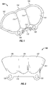
- Figure 1 illustrates a perspective bottom view of a directed beam reflector 100 in accordance with example embodiments of the present disclosure.
- Figure 2 illustrates a top view, or backside view, of the reflector 100 of Figure 1 , in accordance with example embodiments of the present disclosure.
- Figure 1 shows an inner surface 101 of the reflector 100
- Figure 2 shows an outer surface 201 of the reflector 100.
- Figure 3 illustrates a side view of the reflector 100 of Figures 1 and 2 , in accordance with example embodiments of the present disclosure.
- the mounting element 110 includes a coupling element such as an aperture 108 for coupling the reflector to a mounting surface.
- the mounting surface to which the reflector is to be mounted is a circuit board, a spacer, a fixture housing, or the like.
- the coupling element 108 is an aperture which traverses the mounting flange 110 configured to receive a screw threaded therethrough, in which the screw secures the mounting flange 110 to a mounting surface disposed adjacent to the mounting screw.
- the coupling element 108 is a snap, clip, pin, slot, or the like, and the mounting surface includes a corresponding coupling feature.
- the reflector includes one or more alignment elements such as alignment pins 112 for easily aligning the reflector with the mounting surface.
- the alignment feature is a depression, protrusion, slot, or another appropriate alignment or guide feature.
- the first reflector segment 102 includes a portion of a first curved three-dimensional shape
- the second reflector segment 104 includes a portion of a second curved three-dimensional shape
- the third reflector segment 106 includes a portion of a third curved three-dimensional shape.
- Reflector segments 102, 104 and 106 are connected at joints 114 as shown in the example in Figure 1 .
- each of the first, second, and third reflector segments 102, 104, 106 are concave ( Figure 1 ) in the same direction, forming the inner surface 101, and convex ( Figure 2 ) in the same direction, forming the outer surface 201.
- all or a subset of the first, second, and third curved three-dimensional shapes are paraboloids.
- the first reflector segment 102 is on a side of the reflector 100.
- an outer side 301 of the first reflector also forms an outer side 301 of the reflector 100.
- the outer side 301 includes a flank portion 303 which extends beyond the defined portion of the first paraboloid and includes an outer edge 302 which traverses a plane defined by the mounting surface.
- the configuration of the reflector 100 with respect to the mounting surface is described in further detail with reference to Figure 5 .
- the flank portion 303 deviates from, or does not follow, the contour of the paraboloid.
- the reflector 100 is fabricated from a plastic material having appropriate thermal characteristics such that the reflector is able to withstand a high temperature environment, such as that associated with LED lighting.
- the reflector 100 is primary fabricated from a polycarbonate material.
- the inner surface 101 of the reflector 100 is a reflective surface.
- the inner surface 101 is coated with a reflective material such as chrome, aluminum, silver, or the like.
- the process of applying such a coating is a high temperature process. Therefore the reflector 100 would be fabricated from a material of sufficient heat resistance to withstand not only an LED environment, but also the heating involved in applying a reflective coating.
- the reflector 100 includes more or less than three reflector segments.
- Figure 4 illustrates a reflector 400 having a fourth reflector segment 402 in accordance with an example embodiment of the present disclosure.
- the reflector 100 includes only two of the first, second, and third reflector segments 102, 104, 106.
- Figure 5 illustrates a side view of a reflector assembly 500 featuring the reflector 100 of Figures 1, 2 , and 3 , in accordance with an example embodiment of the present disclosure.
- Figure 5 further illustrates the first reflector segment 102 reflecting light from a first LED 506 into a first beam of light 520, in accordance with an example embodiment of the present disclosure.
- the reflector assembly 500 includes the reflector 100, a circuit board 502, and a spacer 504.
- the circuit board 502 includes a coupling element 508 such as an aperture or screw-hole.
- the reflector 100 is mounted onto the circuit board 502 such that the aperture 108 in the mounting element 110 of the reflector and the aperture 508 in the circuit board 502 are aligned and a screw can be threaded therethrough, securing the reflector 100 to the circuit board 502.
- the reflector 100 is mounted onto the circuit board 502 in an orientation in which the inner surface 101 of the reflector 100 faces the circuit board 502 and the outer surface 201 of the reflector 100 faces away from circuit board 502.
- the reflector 100 is mounted onto the circuit board 502 via a different coupling mechanism, such as a clip, snap, groove, and the like.
- the circuit board 502 is mounted on a spacer 504 such that the circuit board 502 is disposed between the reflector 100 and the spacer 504.
- the spacer 504 includes one or more apertures or screw-holes which align with the apertures or screw-holes in the circuit board 502 and the reflector 100.
- a screw is threaded through the reflector 100, the circuit board 502, and the spacer 504, thereby securing the three elements to each other.
- the spacer 504 is also secured to an optical housing on a lighting fixture when installed.
- the alignment pins 112 of the reflector 100 provide accurate alignment and relative positioning between the reflector 100, the circuit board 502, and/or the spacer 504.
- the spacer 504 is secured to the optical housing with one or more screws or another appropriate coupling device or element.
- the spacer 504 provides an angled surface on which the circuit board 502 is mounted, thereby providing an angle between the reflector 100 and the optical housing to which the spacer 504 is mounted.
- the spacer 504 further functions as a heat sink, dissipating a portion of the heat generated by the LEDs 506.
- the LED 506 can be positioned offset from the geometric focus 512 to achieve another desired lighting effect.
- the LED 506 is mounted as close to an edge 518 of the circuit board 502 as practicable, as excess surface area of the circuit board 502 may deflect more light emitted from the LED 506, reducing the overall brightness of the first beam of light 520.
- the outer side 301 of the reflector 100 includes a flank portion 303 and an outer edge 302 which traverses and extends beyond a plane 510 defined by the circuit board 502.
- the extra reflective surface provided by the flank portion 303 provides a stray light baffling function, which reduces the amount to light lost in the fixture and focusses more light into the first beam of light 520.
- Figure 6 illustrates a top view of the reflector assembly 500 of Figure 5 , in accordance with an example embodiment of the present disclosure.
- the circuit board 502 includes a first LED 506, a second LED 612, and a third LED 614 mounted thereon.
- the reflector 100 includes the first reflector segment 102, the second reflector segment 104, and the third reflector segment 106.
- the first reflector segment 102 reflects light emitted by the first LED 506 into a first beam of light 616
- the second reflector segment 104 reflects light emitted by the second LED 612 into a second beam of light 618
- the third reflector segment 106 reflects light emitted by the third LED 612 into a third beam of light 620.
- the reflector 100 includes more or less than three reflector segments, and the reflector assembly 500 includes more or less than three LEDs, thereby producing more or less than three light beams which converge to form the aggregate light beam.
- the reflector segments can be arranged differently to produce a different aggregate light beam. For example, in an embodiment, more reflector segments are arranged side by side to produce a wider aggregate light beam. Alternatively, in an example embodiment, reflector segments are arranged out of line with each other or stacked to produce an aggregate light of more height.
- Figure 7 illustrates an internal view of a light fixture 700 using the reflector 100, in accordance with example embodiments of the present disclosure. Specifically, Figure 7 illustrates the underside of an optical housing 702 of a runway light fixture 700.
- the optical housing 702 houses certain optical and electrical components which support the function of the light fixture 700.
- the light fixture 700 includes a first reflector assembly 500a and a second reflector assembly 500b.
- the first and second reflector assemblies 500a, 500b include first and second reflectors 100a, 100b, and first and second circuit boards 502a, 502b.
- the light fixture 700 further includes a first prism housing 704a and a second prism housing 704b, which house first and second prism 706a, 706b, respectively.
- first and second prisms 706a, 706b and the first and second prism housings 704a, 704b are positioned at a 180° rotation from each other so that light is emitted in opposite directions.
- the first and second reflector assemblies 500a, 500b are mounted onto the optical housing 702 substantially adjacent to and facing the first and second prism housings 704a, 704b, respectively as shown in Figure 7 .
- the prism housings 704a, 704b include a window which exposes the prisms 706a, 706b to the reflectors 100a, 100b.
- the prisms 706a, 706b are substantially perpendicular to the axis of symmetry 516 ( Figure 5 ) of the reflector segments, such that the aggregate light beams 622 ( Figure 6 ) reflected by the reflectors 100a, 100b enter the prisms 706a, 706b.
- the light beams 622 are directed by the prisms 706a, 706b and exit the fixture 700 on the top side (not shown) in a direction substantially parallel to the ground when the fixture 700 is installed on a runway, thus providing flat and focused light for runway lighting.
- the fixture 700 includes more or less than two reflector assemblies 500, and the reflector assemblies are arranged differently.
- the light fixture 700 is an elevated runway light or another type of airfield lighting fixture.
Description
- The present disclosure relates generally to a reflector for a lighting fixture. Specifically, the present disclosure relates generally to an LED reflector for an airfield runway lighting fixture.
- Traditional lighting sources such as incandescent, fluorescent, high intensity discharge (HID) lamps, and the like, are gradually being replaced by light emitting diodes (LEDs) in many industries and applications. LEDs hold several advantages over traditional lighting sources such as increased power efficiency, size to output efficiency, and lifespan, among other others. Thus, many lighting fixtures are being redesigned to use LEDs instead of the traditional lighting sources. However, designing a light fixture to be compatible for use with LEDs may present a suite of engineering challenges, as LEDs typically require different drive electronics, environments, and/or optics than traditional lighting sources. Thus, in order to take advantage of the benefits of LEDs, novel lighting fixtures or LED-compatible electronics, optics, and/or housings components are required. For example, while LEDs are capable of producing a large amount of light for their size, the light is typically given off in a wide directional span. Thus, in order to take advantage of the efficiency of the LEDs and to make the light useful for a particular application, special optical features may be required. Different applications may require unique electronic, optical, or housing components in order to support LED compatibly. In other words, when designing a lighting fixture for LED compatibility, the solutions may be unique and application specific.
- In the area of airfield lighting, runway lighting fixtures have typically used quartz halogen lamps, of which the light emitted is directed into a prism to produce narrow flat light desired for runway lighting. Thus, in order to effectively replace the lamps with LEDs and realize the benefits of LED lighting, it is desired to modify light emitted from the LEDs into a concentrated narrow beam, such that the beam can be efficiently directed into the prism and allow the runway light fixture to produce the desired light output.
- Attention is drawn to
WO 2007 042 493 A1 , which relates to a half-dipped signaling lamp with a base support to be embedded in the ground and at least one light source within the base support. A cap, removably connected to the base support and protruding from the ground, has at least one windowed seat, with an optical prism supported in the window. The optical prism directs the light beam emitted by the light source to the outside. Reflectors direct the light beam emitted by the light source toward the optical prism, to maximize the percentage of light beam coming out of the windowed seat. - In accordance with the present invention, a directed beam reflector assembly as set forth in claim 1 is provided. Further embodiments are inter alia disclosed in the dependent claims.In an example embodiment of the present disclosure, a directed beam reflector includes a first reflector segment and a second reflector segment joined to the first reflector segment. The first reflector segment further includes a first curved reflective surface, in which the first reflector segment comprises a portion of a first curved three-dimensional shape. Likewise, the second reflector segment includes a second curved reflective surface, in which the second reflector segment comprises a portion of a second curved three-dimensional shape. During use, the first curved reflective surface in configured to substantially focus light from a first LED into a first beam of light. Likewise, the second curved reflective surface is configured to focus light from a second LED into a second beam of light. The first beam of light and second beam of light form an aggregate beam of light
- In another example embodiment of the present disclosure, a directed beam reflector assembly includes a circuit board and a reflector. The circuit board includes a first light emitting diode (LED) and a second LED. The reflector is disposed on the circuit board. The reflector includes a first reflector segment and a second reflector segment, in which the first reflector segment is substantially aligned with the first LED and the second reflector segment is substantially aligned with the second LED. During use, the first reflector segment focuses light from the first LED into a first beam of light and the second reflector segment focuses light from the second LED into a second beam of light. The first beam of light and second beam of light form an aggregate beam of light.
- In another example embodiment of the present disclosure, a directed beam reflector includes a reflective surface. The first reflective surface includes one or more concave parabolic surfaces, in which the parabolic surfaces are substantially linearly aligned. Each of the parabolic surfaces include a portion of a paraboloid and reflects light from a light emitting diode (LED) into a focused beam of light.
- For a more complete understanding of the disclosure and the advantages thereof, reference is now made to the following description, in conjunction with the accompanying figures briefly described as follows:
-
Figure 1 illustrates a perspective bottom view of a directed beam reflector and its inner surface, in accordance with example embodiments of the present disclosure; -
Figure 2 illustrates a top view of the directed beam reflector ofFigure 1 and its outer surface, in accordance with example embodiments of the present disclosure; -
Figure 3 illustrates a side view of the directed beam reflector ofFigures 1 and 2 , in accordance with example embodiments of the present disclosure; -
Figure 4 illustrates a perspective bottom view of an alternate embodiment of a directed beam reflector, in accordance with example embodiments of the present disclosure; -
Figure 5 illustrates a side view of a reflector assembly, in accordance with example embodiments of the present disclosure; -
Figure 6 illustrates a top view of the reflector assembly ofFigure 5 , in accordance with embodiments of the present disclosure; and -
Figure 7 illustrates an internal view of a light fixture including the reflector assembly ofFigures 5 and 6 . - The drawings illustrate only example embodiments of the disclosure and are therefore not to be considered limiting of its scope, as the disclosure may admit to other equally effective embodiments. The elements and features shown in the drawings are not necessarily to scale, emphasis instead being placed upon clearly illustrating the principles of example embodiments of the present disclosure. Additionally, certain dimensions may be exaggerated to help visually convey such principles.
- In the following paragraphs, the present disclosure will be described in further detail by way of examples with reference to the attached drawings. In the description, well known components, methods, and/or processing techniques are omitted or briefly described so as not to obscure the disclosure. As used herein, the "present disclosure" refers to any one of the embodiments of the disclosure described herein and any equivalents. Furthermore, reference to various feature(s) of the "present disclosure" is not to suggest that all embodiments must include the referenced feature(s). The present disclosure provides systems and methods of reflecting light emitting from LEDs into a focused beam and aggregate beam appropriate for use with airfield runway lighting features, and which provide the benefits of LED lighting while meeting the requirements for runway lighting.
- In certain example embodiments, the present disclosure provides a reflector capable of directing light from one or more light sources into a narrow beam of light, in which the light beam reaches a high brightness while the light sources require less driver power relative to the brightness of the light beam. In the present disclosure, the reflector is described in an airfield lighting environment, specifically, as an optical component of an airfield runway light fixture. However, the reflector is usable in a variety of other lighting fixtures and applications other than airfield lighting. Similarly, in the present disclosure, the reflector is used with light emitting diodes (LEDs) as the one or more light sources. While the example embodiments and applications described in this disclosure use LEDs, it is to be appreciated that in other example embodiments and applications, the reflector can be used with other types of light sources while remaining within the scope of this disclosure. Any disclosure of dimensions, proportions, or particular geometries in the description or in the figures is for conceptual and example purposes and is not limiting.
-
Figure 1 illustrates a perspective bottom view of a directedbeam reflector 100 in accordance with example embodiments of the present disclosure.Figure 2 illustrates a top view, or backside view, of thereflector 100 ofFigure 1 , in accordance with example embodiments of the present disclosure. Specifically,Figure 1 shows aninner surface 101 of thereflector 100 andFigure 2 shows anouter surface 201 of thereflector 100.Figure 3 illustrates a side view of thereflector 100 ofFigures 1 and 2 , in accordance with example embodiments of the present disclosure. Referring toFigures 1, 2 , and3 , in certain example embodiments, the directedbeam reflector 100 includes afirst reflector segment 102, asecond reflector segment 104, and athird reflector segment 106, in which thefirst reflector segment 102 is coupled to thesecond reflector segment 104, and thethird reflector segment 106 is coupled to thesecond reflector segment 104 opposite the first reflector segment. In certain example embodiments, the first, second, andthird reflector segments reflector 100 further includes a mounting element, such as a mountingflange 110, coupled to at least one of the first, second, and third reflector segments. In certain example embodiments, the mountingelement 110 includes a coupling element such as anaperture 108 for coupling the reflector to a mounting surface. In certain example embodiment, the mounting surface to which the reflector is to be mounted is a circuit board, a spacer, a fixture housing, or the like. In the presently illustrated embodiment, thecoupling element 108 is an aperture which traverses the mountingflange 110 configured to receive a screw threaded therethrough, in which the screw secures the mountingflange 110 to a mounting surface disposed adjacent to the mounting screw. In another example embodiment, thecoupling element 108 is a snap, clip, pin, slot, or the like, and the mounting surface includes a corresponding coupling feature. In certain example embodiments, the reflector includes one or more alignment elements such as alignment pins 112 for easily aligning the reflector with the mounting surface. In another example embodiment, the alignment feature is a depression, protrusion, slot, or another appropriate alignment or guide feature. - In certain example embodiments, the
first reflector segment 102 includes a portion of a first curved three-dimensional shape, thesecond reflector segment 104 includes a portion of a second curved three-dimensional shape, and thethird reflector segment 106 includes a portion of a third curved three-dimensional shape.Reflector segments joints 114 as shown in the example inFigure 1 . In certain example embodiments, and as illustrated inFigures 1 and 2 , each of the first, second, andthird reflector segments Figure 1 ) in the same direction, forming theinner surface 101, and convex (Figure 2 ) in the same direction, forming theouter surface 201. In certain example embodiments, all or a subset of the first, second, and third curved three-dimensional shapes are paraboloids. - In certain example embodiments, the
first reflector segment 102 includes a portion of a first paraboloid, in which the portion is defined or bounded by a partial revolution of the paraboloid and a plane traversing the axis of symmetry of the paraboloid. In certain example embodiments, the plane is orthogonal to the axis of symmetry. In certain other example embodiments, the plane is not orthogonal to the axis of symmetry. Likewise, the second andthird reflector segments - In certain example embodiments, the first, second, and
third reflector segments Figures 1 , the first andthird reflector segments second reflector segment 104 comprises a smaller portion of its respective paraboloid. In other words, thesecond reflector segment 104 is defined by fewer degrees of revolution of the second paraboloid. Thus, in certain embodiments, the first, second, andthird reflector segments - Referring to
Figure 3 , in certain example embodiments, thefirst reflector segment 102 is on a side of thereflector 100. Thus, in such an embodiment, anouter side 301 of the first reflector also forms anouter side 301 of thereflector 100. In certain example embodiments, theouter side 301 includes aflank portion 303 which extends beyond the defined portion of the first paraboloid and includes anouter edge 302 which traverses a plane defined by the mounting surface. The configuration of thereflector 100 with respect to the mounting surface is described in further detail with reference toFigure 5 . In certain example embodiments, theflank portion 303 deviates from, or does not follow, the contour of the paraboloid. - In certain example embodiments, the
reflector 100 is fabricated from a plastic material having appropriate thermal characteristics such that the reflector is able to withstand a high temperature environment, such as that associated with LED lighting. For example, in one or more example embodiments, thereflector 100 is primary fabricated from a polycarbonate material. Theinner surface 101 of thereflector 100 is a reflective surface. In certain example embodiments, theinner surface 101 is coated with a reflective material such as chrome, aluminum, silver, or the like. In certain example embodiments, the process of applying such a coating is a high temperature process. Therefore thereflector 100 would be fabricated from a material of sufficient heat resistance to withstand not only an LED environment, but also the heating involved in applying a reflective coating. - In certain example embodiments, the
reflector 100 includes more or less than three reflector segments. For example,Figure 4 illustrates areflector 400 having afourth reflector segment 402 in accordance with an example embodiment of the present disclosure. Alternatively, in certain example embodiments, thereflector 100 includes only two of the first, second, andthird reflector segments -
Figure 5 illustrates a side view of areflector assembly 500 featuring thereflector 100 ofFigures 1, 2 , and3 , in accordance with an example embodiment of the present disclosure.Figure 5 further illustrates thefirst reflector segment 102 reflecting light from afirst LED 506 into a first beam oflight 520, in accordance with an example embodiment of the present disclosure. Referring toFigure 5 , in certain example embodiments, thereflector assembly 500 includes thereflector 100, acircuit board 502, and aspacer 504. In certain example embodiments, thecircuit board 502 includes acoupling element 508 such as an aperture or screw-hole. Thereflector 100 is mounted onto thecircuit board 502 such that theaperture 108 in the mountingelement 110 of the reflector and theaperture 508 in thecircuit board 502 are aligned and a screw can be threaded therethrough, securing thereflector 100 to thecircuit board 502. In an example embodiment, thereflector 100 is mounted onto thecircuit board 502 in an orientation in which theinner surface 101 of thereflector 100 faces thecircuit board 502 and theouter surface 201 of thereflector 100 faces away fromcircuit board 502. - In certain other example embodiments, the
reflector 100 is mounted onto thecircuit board 502 via a different coupling mechanism, such as a clip, snap, groove, and the like. In certain example embodiments, thecircuit board 502 is mounted on aspacer 504 such that thecircuit board 502 is disposed between thereflector 100 and thespacer 504. In an example embodiment, thespacer 504 includes one or more apertures or screw-holes which align with the apertures or screw-holes in thecircuit board 502 and thereflector 100. In such an embodiment, a screw is threaded through thereflector 100, thecircuit board 502, and thespacer 504, thereby securing the three elements to each other. In an example embodiment, thespacer 504 is also secured to an optical housing on a lighting fixture when installed. Additionally, in certain example embodiments, the alignment pins 112 of thereflector 100 provide accurate alignment and relative positioning between thereflector 100, thecircuit board 502, and/or thespacer 504. In certain example embodiments, thespacer 504 is secured to the optical housing with one or more screws or another appropriate coupling device or element. In an example embodiment, thespacer 504 provides an angled surface on which thecircuit board 502 is mounted, thereby providing an angle between thereflector 100 and the optical housing to which thespacer 504 is mounted. In certain example embodiments, thespacer 504 further functions as a heat sink, dissipating a portion of the heat generated by theLEDs 506. - The
circuit board 502 further includes one ormore LEDs 506 disposed thereon. In certain example embodiments, theLED 506 is a surfacemount LED package 506. TheLED 506 is directed upwards towards theinner surface 101 of thereflector 100. In one example embodiment, thecircuit board 502 has asmany LEDs 506 as the reflector has reflector segments, in which eachLED 506 corresponds to and is positioned under one of the reflector segments. In an example embodiment, theLED 506 is positioned with respect to thefirst reflector segment 102. Specifically, in the example embodiment, theLED 506 and thereflector 100 are oriented on thecircuit board 502 such that theLED 506 is substantially positioned at the geometric focus 512 of thefirst paraboloid 504, of which the first reflector segment comprises a portion, as described above. Thus, light given off by theLED 506 is reflected by thereflector 100 in a direction substantially parallel to theoptical axis 516 of thefirst paraboloid 514, forming a first beam oflight 520. Theoptical axis 516 is at an angle to thecircuit board 502, which directs the first beam oflight 520 in the angle with respect to thecircuit board 502. Such an optical angle facilitates optical efficiency of the reflector segment and the lighting fixture and/or housing in which thereflector 100 is installed. However, given that the light emitting area of theLED 506 spans an area larger than one geometric point, some of the light emitted does not originate from the exact geometric focus 512 and is reflected at an slight angle to the axis ofsymmetry 516. In certain example embodiments, theLED 506 can be positioned offset from the geometric focus 512 to achieve another desired lighting effect. - In certain example embodiments, the
LED 506 is mounted as close to an edge 518 of thecircuit board 502 as practicable, as excess surface area of thecircuit board 502 may deflect more light emitted from theLED 506, reducing the overall brightness of the first beam oflight 520. As discussed above, in an example embodiment, theouter side 301 of thereflector 100 includes aflank portion 303 and anouter edge 302 which traverses and extends beyond aplane 510 defined by thecircuit board 502. The extra reflective surface provided by theflank portion 303 provides a stray light baffling function, which reduces the amount to light lost in the fixture and focusses more light into the first beam oflight 520. -
Figure 6 illustrates a top view of thereflector assembly 500 ofFigure 5 , in accordance with an example embodiment of the present disclosure. Referring toFigure 6 , in an example embodiment, thecircuit board 502 includes afirst LED 506, asecond LED 612, and athird LED 614 mounted thereon. In the example embodiment, thereflector 100 includes thefirst reflector segment 102, thesecond reflector segment 104, and thethird reflector segment 106. Accordingly, thefirst reflector segment 102 reflects light emitted by thefirst LED 506 into a first beam oflight 616, thesecond reflector segment 104 reflects light emitted by thesecond LED 612 into a second beam oflight 618, and thethird reflector segment 106 reflects light emitted by thethird LED 612 into a third beam oflight 620. - In certain example embodiments, the first, second, and third beams of
light aggregate beam 622. When used in an airfield runway lighting application, such convergence generates a beam which meets Federal Aviation Administration (FAA) standards and/or international airfield standards. In certain example embodiments, the angle of convergence is defined as "full-width half maximum", or the complete width across the beam at the half power point. For example, in one embodiment, the angle of convergence is approximately 10° horizontally (left to right direction inFigure 6 ) and 4.5° vertically (top to bottom direction inFigure 5 ). Thus, theaggregate beam 622 is wider than it is tall. In certain example embodiments, the horizontal angle of convergence ranges from approximately 8° to 12° and the vertical angle of convergence ranges from approximately 3° to 5°. In other example embodiments, the horizontal and vertical angles of convergence are outside of these ranges. - In certain example embodiments, the
reflector 100 includes more or less than three reflector segments, and thereflector assembly 500 includes more or less than three LEDs, thereby producing more or less than three light beams which converge to form the aggregate light beam. The reflector segments can be arranged differently to produce a different aggregate light beam. For example, in an embodiment, more reflector segments are arranged side by side to produce a wider aggregate light beam. Alternatively, in an example embodiment, reflector segments are arranged out of line with each other or stacked to produce an aggregate light of more height. -
Figure 7 illustrates an internal view of alight fixture 700 using thereflector 100, in accordance with example embodiments of the present disclosure. Specifically,Figure 7 illustrates the underside of anoptical housing 702 of arunway light fixture 700. In certain example embodiments, theoptical housing 702 houses certain optical and electrical components which support the function of thelight fixture 700. In an example embodiment, thelight fixture 700 includes afirst reflector assembly 500a and asecond reflector assembly 500b. Respectively, the first andsecond reflector assemblies second reflectors 100a, 100b, and first andsecond circuit boards light fixture 700 further includes afirst prism housing 704a and asecond prism housing 704b, which house first andsecond prism second prisms second prism housings second reflector assemblies optical housing 702 substantially adjacent to and facing the first andsecond prism housings Figure 7 . Theprism housings prisms reflectors 100a, 100b. Specifically, theprisms Figure 5 ) of the reflector segments, such that the aggregate light beams 622 (Figure 6 ) reflected by thereflectors 100a, 100b enter theprisms prisms fixture 700 on the top side (not shown) in a direction substantially parallel to the ground when thefixture 700 is installed on a runway, thus providing flat and focused light for runway lighting. In certain example embodiments, thefixture 700 includes more or less than tworeflector assemblies 500, and the reflector assemblies are arranged differently. In certain example embodiments, thelight fixture 700 is an elevated runway light or another type of airfield lighting fixture. - Although embodiments of the present disclosure have been described herein in detail, the descriptions are by way of example. The features of the disclosure described herein are representative and, in alternative embodiments, certain features and elements may be added or omitted. Additionally, modifications to aspects of the embodiments described herein may be made by those skilled in the art without departing from the scope of the present disclosure defined in the following claims, the scope of which are to be accorded the broadest interpretation so as to encompass modifications and equivalent structures.
Claims (11)
- A directed beam reflector assembly, comprising:a circuit board (502) comprising a first light emitting diode, LED (506) and a second LED (612), wherein the circuit board (502) defines a plane, and wherein the circuit board (502) comprises one or more coupling apertures (508) for coupling a reflector (100); andthe reflector (100) comprising:a first reflector segment (102) having a first optical axis (516) and a second reflector segment (104) having a second optical axis (516) and, wherein the first reflector segment (102) is substantially aligned with the first LED (506) and the second reflector segment (104) is substantially aligned with the second LED (612), anda mounting flange (110) integral to the reflector (100) and configured to mount the reflector (100) onto the circuit board (502):wherein the reflector (100) is mounted on the circuit board (502) such that:an inner surface (101) of the first reflector segment (102) extends from the circuit board (502) at the mounting flange (110) over the first LED (506) and towards an edge (518) of the circuit board (502) that is adjacent the first LED (506),an inner surface (101) of the second reflector segment (104) extends from the circuit board (502) at the mounting flange (110) over the second LED (612) and towards an edge (518) of the circuit board (502) that is adjacent the second LED (612), andthe plane of the circuit board (502) forms an angle that is acute with the first optical axis (516) and the second optical axis (516) to improve an optical efficiency of the first reflector segment (102) and the second reflector segment (104), andwherein the first reflector segment (102) substantially focuses light from the first LED (506) into a first beam of light (616) that is directed at the angle with respect to the plane defined by the circuit board (502); the second reflector segment (104) substantially focuses light from the second LED (612) into a second beam of light (618) that is directed at the angle with respect to the plane defined by the circuit board (502); andthe first beam of light (616) and second beam of light (618) form an aggregate beam of light (622).
- The directed beam reflector assembly of Claim 1, wherein the reflector (100) comprises a right edge (302) and a left edge (302), wherein the right and left edges (302) extend beyond the plane defined by the circuit board (502).
- The directed beam reflector assembly of Claim 1, wherein the mounting flange (110) is mounted on the circuit board (502) and the circuit board (502) is coupled to a spacer (504) via one or more screws.
- The directed beam reflector assembly of Claim 1, wherein:the first reflector segment (102) comprises a first curved reflective surface (101) and a portion of a first curved three-dimensional shape; andthe second reflector segment (104) comprises a second curved reflective surface (101) joined to the first reflector portion, and comprises a portion of a second curved three-dimensional shape.
- The directed beam reflector assembly of Claim 4, wherein the reflector (100) further comprises a third reflector segment (106) joined to the second reflector segment (104) opposite the first reflector segment (102), the third reflector segment (106) comprising a third curved reflective surface (101) and a portion of a third curved three-dimensional shape.
- The directed beam reflector assembly of Claim 4, wherein the first curved three-dimensional shape and the second curved three-dimensional shape comprise first and second paraboloids, respectively.
- The directed beam reflector assembly of Claim 6, wherein the first LED (506) is positioned at approximately a geometric focus (512) of the first paraboloid.
- The directed beam reflector of Claim 1, wherein a horizontal convergence of the aggregate beam light (622) is approximately 8 to 12 degrees and a vertical convergence of the aggregate beam light (622) is approximately 3 to 5 degrees.
- The directed beam reflector assembly of Claim 3, wherein the spacer (504) includes one or more apertures that are aligned with the one or more coupling apertures of the circuit board (502) when the circuit board (502) and the reflector (100) are mounted onto the spacer (504).
- The directed beam reflector assembly of Claim 1, wherein the directed beam reflector assembly is placed adjacent to a prism housing (704) in an optical housing (702) such that the aggregate beam of light (622) from the reflector (100) enters the prism housing (704) through a prism housing window and is directed by a prism (706) in the prism housing (704) to exit the optical housing (702).
- The directed beam reflector assembly of Claim 1, wherein the aggregate beam of light (622) is wider than it is tall, width being measured in a horizontal direction traversing the reflector (100).
Applications Claiming Priority (2)
| Application Number | Priority Date | Filing Date | Title |
|---|---|---|---|
| US13/933,818 US9696008B2 (en) | 2013-07-02 | 2013-07-02 | Reflector for directed beam LED illumination |
| PCT/US2014/045016 WO2015002928A1 (en) | 2013-07-02 | 2014-07-01 | Reflector for directed beam led illumination |
Publications (3)
| Publication Number | Publication Date |
|---|---|
| EP3027963A1 EP3027963A1 (en) | 2016-06-08 |
| EP3027963A4 EP3027963A4 (en) | 2016-11-23 |
| EP3027963B1 true EP3027963B1 (en) | 2018-04-18 |
Family
ID=52132692
Family Applications (1)
| Application Number | Title | Priority Date | Filing Date |
|---|---|---|---|
| EP14820677.4A Active EP3027963B1 (en) | 2013-07-02 | 2014-07-01 | Reflector for directed beam led illumination |
Country Status (6)
| Country | Link |
|---|---|
| US (1) | US9696008B2 (en) |
| EP (1) | EP3027963B1 (en) |
| KR (1) | KR102304154B1 (en) |
| CN (1) | CN105378376B (en) |
| ES (1) | ES2675008T3 (en) |
| WO (1) | WO2015002928A1 (en) |
Families Citing this family (9)
| Publication number | Priority date | Publication date | Assignee | Title |
|---|---|---|---|---|
| US10253956B2 (en) | 2015-08-26 | 2019-04-09 | Abl Ip Holding Llc | LED luminaire with mounting structure for LED circuit board |
| TWM547065U (en) * | 2017-04-14 | 2017-08-11 | 軒帆光電科技股份有限公司 | Light source module for illumination device |
| US10766637B2 (en) | 2017-05-09 | 2020-09-08 | Eaton Intelligent Power Limited | Airfield light |
| CA3004401A1 (en) | 2017-05-09 | 2018-11-09 | Eaton Intelligent Power Limited | Airfield light |
| CN110997492B (en) * | 2017-08-15 | 2023-07-21 | 伊顿智能动力有限公司 | Airport lamp |
| CN108036203A (en) * | 2017-12-13 | 2018-05-15 | 上海航安机场设备有限公司 | LED light component for lead-in-light system |
| US10251279B1 (en) | 2018-01-04 | 2019-04-02 | Abl Ip Holding Llc | Printed circuit board mounting with tabs |
| EP3738889A1 (en) * | 2019-05-17 | 2020-11-18 | Goodrich Lighting Systems GmbH | Lighting device, aircraft comprising such lighting device, and method for manufacturing a lighting device |
| KR102588715B1 (en) | 2022-10-14 | 2023-10-13 | 박웅기 | Device for preventing leak of gas |
Family Cites Families (31)
| Publication number | Priority date | Publication date | Assignee | Title |
|---|---|---|---|---|
| US3390262A (en) * | 1965-05-24 | 1968-06-25 | Sylvania Electric Prod | Multizone high power light reflector |
| US4242725A (en) * | 1977-12-01 | 1980-12-30 | Sun Chemical Corporation | Light reflector structure |
| US4261030A (en) * | 1979-03-15 | 1981-04-07 | Esquire, Inc. | Wrap-around parabolic light fixture and method for manufacture |
| US4336576A (en) * | 1980-04-07 | 1982-06-22 | Crabtree Daniel B | Lighting apparatus |
| EP1421316B1 (en) * | 2001-08-31 | 2007-10-17 | Gentex Corporation | Vehicle lamp assembly with heat sink |
| JP4027688B2 (en) * | 2002-03-15 | 2007-12-26 | 株式会社小糸製作所 | Vehicle lighting |
| US6851835B2 (en) | 2002-12-17 | 2005-02-08 | Whelen Engineering Company, Inc. | Large area shallow-depth full-fill LED light assembly |
| US8197110B2 (en) * | 2003-10-10 | 2012-06-12 | Federal Signal Corporation | Light assembly incorporating reflective features |
| EP1671063B1 (en) | 2003-10-10 | 2013-03-06 | Federal Signal Corporation | Light assembly |
| US7070301B2 (en) | 2003-11-04 | 2006-07-04 | 3M Innovative Properties Company | Side reflector for illumination using light emitting diode |
| JP2005166590A (en) * | 2003-12-05 | 2005-06-23 | Koito Mfg Co Ltd | Vehicular headlamp |
| US7040782B2 (en) | 2004-02-19 | 2006-05-09 | Gelcore, Llc | Off-axis parabolic reflector |
| ITBO20050606A1 (en) | 2005-10-11 | 2007-04-12 | Ocem Spa | SIGNALING LIGHT WITH SEMI-LEVEL |
| US7824067B2 (en) | 2007-03-21 | 2010-11-02 | Thomas & Betts International, Inc. | Emergency light fixture having an efficient reflector assembly |
| JP5212785B2 (en) * | 2008-02-22 | 2013-06-19 | スタンレー電気株式会社 | Vehicle headlamp |
| US20100226139A1 (en) * | 2008-12-05 | 2010-09-09 | Permlight Products, Inc. | Led-based light engine |
| JP2011076858A (en) * | 2009-09-30 | 2011-04-14 | Koito Mfg Co Ltd | Vehicular lighting fixture |
| WO2011063145A1 (en) * | 2009-11-18 | 2011-05-26 | Brian Edward Richardson | Internal collecting reflector optics for leds |
| CN102087004B (en) * | 2009-12-03 | 2014-06-11 | 马士科技有限公司 | LED (Light Emitting Diode) lamp and reflecting cup therein |
| DE102010018178A1 (en) | 2010-04-22 | 2011-10-27 | Hella Kgaa Hueck & Co. | Lighting device for an airport runway |
| JP5338746B2 (en) * | 2010-05-12 | 2013-11-13 | 市光工業株式会社 | Vehicle lighting |
| EP2428725B1 (en) * | 2010-09-10 | 2019-11-20 | Koito Manufacturing Co., Ltd. | Vehicle headlamp |
| US8672515B2 (en) * | 2010-11-15 | 2014-03-18 | Power Products, Llc | Marine spotlight |
| US8485684B2 (en) | 2011-05-13 | 2013-07-16 | GE Lighting Solutions, LLC | LED roadway luminaire |
| KR101234323B1 (en) * | 2011-05-25 | 2013-02-18 | 현대모비스 주식회사 | Head lamp apparatus for vehicle |
| US8616724B2 (en) | 2011-06-23 | 2013-12-31 | Cree, Inc. | Solid state directional lamp including retroreflective, multi-element directional lamp optic |
| JP5716576B2 (en) * | 2011-06-30 | 2015-05-13 | スタンレー電気株式会社 | Vehicle lamp unit |
| JP2013093157A (en) * | 2011-10-25 | 2013-05-16 | Ichikoh Ind Ltd | Vehicular headlight |
| CN202432395U (en) | 2012-01-13 | 2012-09-12 | 佛山市国星光电股份有限公司 | Automobile headlamp based on LED (light-emitting diode) three-dimensional encapsulation |
| JP5945857B2 (en) * | 2012-01-24 | 2016-07-05 | スタンレー電気株式会社 | Vehicle headlamp and light guide lens |
| JP6195747B2 (en) * | 2012-10-22 | 2017-09-13 | 株式会社小糸製作所 | Lamp unit and vehicle lamp |
-
2013
- 2013-07-02 US US13/933,818 patent/US9696008B2/en active Active
-
2014
- 2014-07-01 CN CN201480038339.9A patent/CN105378376B/en active Active
- 2014-07-01 WO PCT/US2014/045016 patent/WO2015002928A1/en active Application Filing
- 2014-07-01 ES ES14820677.4T patent/ES2675008T3/en active Active
- 2014-07-01 EP EP14820677.4A patent/EP3027963B1/en active Active
- 2014-07-01 KR KR1020167002740A patent/KR102304154B1/en active IP Right Grant
Non-Patent Citations (1)
| Title |
|---|
| None * |
Also Published As
| Publication number | Publication date |
|---|---|
| KR20160027142A (en) | 2016-03-09 |
| US20150009678A1 (en) | 2015-01-08 |
| KR102304154B1 (en) | 2021-09-27 |
| EP3027963A4 (en) | 2016-11-23 |
| US9696008B2 (en) | 2017-07-04 |
| ES2675008T3 (en) | 2018-07-05 |
| CN105378376A (en) | 2016-03-02 |
| CN105378376B (en) | 2019-01-15 |
| EP3027963A1 (en) | 2016-06-08 |
| WO2015002928A1 (en) | 2015-01-08 |
Similar Documents
| Publication | Publication Date | Title |
|---|---|---|
| EP3027963B1 (en) | Reflector for directed beam led illumination | |
| KR101601261B1 (en) | Orientable lens for a led fixture | |
| RU2502919C2 (en) | Aligned lens for light diode lamp | |
| US20140218933A1 (en) | Detachable lamp | |
| US7300185B1 (en) | Quadrilateral symmetrical light source | |
| CN105090887B (en) | LED lamp and its optical lens | |
| US20160223164A1 (en) | Wall washer lighting system with light emitter, optical lens and reflector | |
| US20170130935A1 (en) | Optical lens and a spotlight including the same | |
| JP2016095954A (en) | Led light distribution control lens, optical source module utilizing the same, and tunnel illumination lamp | |
| CN103672461B (en) | LED lamp | |
| EP3877696B1 (en) | A lighting system | |
| JP6241599B2 (en) | Lighting device | |
| TWI386592B (en) | Led fluorescent lamp | |
| US20170002999A1 (en) | Discontinuous annular reflector for lamp | |
| US8858033B1 (en) | Lamp change system for luminaires using quasi point light sources and related heat sinking | |
| KR20150032504A (en) | Led road lamp | |
| US20190093833A1 (en) | Filter lens, led lamp with filter lens and illumination system | |
| TWI524036B (en) | Light apparatus | |
| KR20140125698A (en) | The LED bulb lighting lamp equipped with reflector | |
| JP6241601B2 (en) | Lighting device | |
| US10808892B2 (en) | Light source for a luminaire | |
| US10119680B2 (en) | Retrofit light emitting diode fixture for a back box | |
| KR20150078209A (en) | Lighting device | |
| KR20180137843A (en) | Lighting apparatus with light-diffusing function | |
| KR20170043351A (en) | Led lamp |
Legal Events
| Date | Code | Title | Description |
|---|---|---|---|
| PUAI | Public reference made under article 153(3) epc to a published international application that has entered the european phase |
Free format text: ORIGINAL CODE: 0009012 |
|
| 17P | Request for examination filed |
Effective date: 20151229 |
|
| AK | Designated contracting states |
Kind code of ref document: A1 Designated state(s): AL AT BE BG CH CY CZ DE DK EE ES FI FR GB GR HR HU IE IS IT LI LT LU LV MC MK MT NL NO PL PT RO RS SE SI SK SM TR |
|
| AX | Request for extension of the european patent |
Extension state: BA ME |
|
| DAX | Request for extension of the european patent (deleted) | ||
| A4 | Supplementary search report drawn up and despatched |
Effective date: 20161020 |
|
| RIC1 | Information provided on ipc code assigned before grant |
Ipc: F21V 7/04 20060101ALI20161014BHEP Ipc: F21V 7/22 20060101ALN20161014BHEP Ipc: F21V 19/00 20060101ALN20161014BHEP Ipc: F21Y 101/00 20160101ALI20161014BHEP Ipc: F21V 7/06 20060101AFI20161014BHEP Ipc: F21Y 105/10 20160101ALN20161014BHEP Ipc: F21W 111/06 20060101ALI20161014BHEP Ipc: F21V 17/12 20060101ALN20161014BHEP Ipc: F21V 7/09 20060101ALI20161014BHEP Ipc: F21Y 115/10 20160101ALN20161014BHEP |
|
| RIC1 | Information provided on ipc code assigned before grant |
Ipc: F21V 7/09 20060101ALI20171002BHEP Ipc: F21V 17/12 20060101ALN20171002BHEP Ipc: F21Y 105/10 20160101ALN20171002BHEP Ipc: F21W 111/06 20060101ALI20171002BHEP Ipc: F21Y 101/00 20160101ALI20171002BHEP Ipc: F21V 7/04 20060101ALI20171002BHEP Ipc: F21V 7/06 20060101AFI20171002BHEP Ipc: F21V 7/22 20060101ALN20171002BHEP Ipc: F21V 19/00 20060101ALN20171002BHEP Ipc: F21Y 115/10 20160101ALN20171002BHEP |
|
| GRAP | Despatch of communication of intention to grant a patent |
Free format text: ORIGINAL CODE: EPIDOSNIGR1 |
|
| INTG | Intention to grant announced |
Effective date: 20171113 |
|
| GRAS | Grant fee paid |
Free format text: ORIGINAL CODE: EPIDOSNIGR3 |
|
| GRAA | (expected) grant |
Free format text: ORIGINAL CODE: 0009210 |
|
| AK | Designated contracting states |
Kind code of ref document: B1 Designated state(s): AL AT BE BG CH CY CZ DE DK EE ES FI FR GB GR HR HU IE IS IT LI LT LU LV MC MK MT NL NO PL PT RO RS SE SI SK SM TR |
|
| REG | Reference to a national code |
Ref country code: GB Ref legal event code: FG4D |
|
| REG | Reference to a national code |
Ref country code: CH Ref legal event code: EP |
|
| REG | Reference to a national code |
Ref country code: AT Ref legal event code: REF Ref document number: 990900 Country of ref document: AT Kind code of ref document: T Effective date: 20180515 |
|
| REG | Reference to a national code |
Ref country code: IE Ref legal event code: FG4D |
|
| REG | Reference to a national code |
Ref country code: DE Ref legal event code: R096 Ref document number: 602014024217 Country of ref document: DE |
|
| REG | Reference to a national code |
Ref country code: FR Ref legal event code: PLFP Year of fee payment: 5 |
|
| REG | Reference to a national code |
Ref country code: ES Ref legal event code: FG2A Ref document number: 2675008 Country of ref document: ES Kind code of ref document: T3 Effective date: 20180705 |
|
| REG | Reference to a national code |
Ref country code: NL Ref legal event code: MP Effective date: 20180418 |
|
| REG | Reference to a national code |
Ref country code: LT Ref legal event code: MG4D |
|
| PG25 | Lapsed in a contracting state [announced via postgrant information from national office to epo] |
Ref country code: NL Free format text: LAPSE BECAUSE OF FAILURE TO SUBMIT A TRANSLATION OF THE DESCRIPTION OR TO PAY THE FEE WITHIN THE PRESCRIBED TIME-LIMIT Effective date: 20180418 |
|
| PG25 | Lapsed in a contracting state [announced via postgrant information from national office to epo] |
Ref country code: AL Free format text: LAPSE BECAUSE OF FAILURE TO SUBMIT A TRANSLATION OF THE DESCRIPTION OR TO PAY THE FEE WITHIN THE PRESCRIBED TIME-LIMIT Effective date: 20180418 Ref country code: BG Free format text: LAPSE BECAUSE OF FAILURE TO SUBMIT A TRANSLATION OF THE DESCRIPTION OR TO PAY THE FEE WITHIN THE PRESCRIBED TIME-LIMIT Effective date: 20180718 Ref country code: FI Free format text: LAPSE BECAUSE OF FAILURE TO SUBMIT A TRANSLATION OF THE DESCRIPTION OR TO PAY THE FEE WITHIN THE PRESCRIBED TIME-LIMIT Effective date: 20180418 Ref country code: PL Free format text: LAPSE BECAUSE OF FAILURE TO SUBMIT A TRANSLATION OF THE DESCRIPTION OR TO PAY THE FEE WITHIN THE PRESCRIBED TIME-LIMIT Effective date: 20180418 Ref country code: LT Free format text: LAPSE BECAUSE OF FAILURE TO SUBMIT A TRANSLATION OF THE DESCRIPTION OR TO PAY THE FEE WITHIN THE PRESCRIBED TIME-LIMIT Effective date: 20180418 Ref country code: SE Free format text: LAPSE BECAUSE OF FAILURE TO SUBMIT A TRANSLATION OF THE DESCRIPTION OR TO PAY THE FEE WITHIN THE PRESCRIBED TIME-LIMIT Effective date: 20180418 Ref country code: NO Free format text: LAPSE BECAUSE OF FAILURE TO SUBMIT A TRANSLATION OF THE DESCRIPTION OR TO PAY THE FEE WITHIN THE PRESCRIBED TIME-LIMIT Effective date: 20180718 |
|
| PG25 | Lapsed in a contracting state [announced via postgrant information from national office to epo] |
Ref country code: HR Free format text: LAPSE BECAUSE OF FAILURE TO SUBMIT A TRANSLATION OF THE DESCRIPTION OR TO PAY THE FEE WITHIN THE PRESCRIBED TIME-LIMIT Effective date: 20180418 Ref country code: GR Free format text: LAPSE BECAUSE OF FAILURE TO SUBMIT A TRANSLATION OF THE DESCRIPTION OR TO PAY THE FEE WITHIN THE PRESCRIBED TIME-LIMIT Effective date: 20180719 Ref country code: LV Free format text: LAPSE BECAUSE OF FAILURE TO SUBMIT A TRANSLATION OF THE DESCRIPTION OR TO PAY THE FEE WITHIN THE PRESCRIBED TIME-LIMIT Effective date: 20180418 Ref country code: RS Free format text: LAPSE BECAUSE OF FAILURE TO SUBMIT A TRANSLATION OF THE DESCRIPTION OR TO PAY THE FEE WITHIN THE PRESCRIBED TIME-LIMIT Effective date: 20180418 |
|
| REG | Reference to a national code |
Ref country code: AT Ref legal event code: MK05 Ref document number: 990900 Country of ref document: AT Kind code of ref document: T Effective date: 20180418 |
|
| PG25 | Lapsed in a contracting state [announced via postgrant information from national office to epo] |
Ref country code: PT Free format text: LAPSE BECAUSE OF FAILURE TO SUBMIT A TRANSLATION OF THE DESCRIPTION OR TO PAY THE FEE WITHIN THE PRESCRIBED TIME-LIMIT Effective date: 20180820 |
|
| REG | Reference to a national code |
Ref country code: DE Ref legal event code: R097 Ref document number: 602014024217 Country of ref document: DE |
|
| PG25 | Lapsed in a contracting state [announced via postgrant information from national office to epo] |
Ref country code: SK Free format text: LAPSE BECAUSE OF FAILURE TO SUBMIT A TRANSLATION OF THE DESCRIPTION OR TO PAY THE FEE WITHIN THE PRESCRIBED TIME-LIMIT Effective date: 20180418 Ref country code: EE Free format text: LAPSE BECAUSE OF FAILURE TO SUBMIT A TRANSLATION OF THE DESCRIPTION OR TO PAY THE FEE WITHIN THE PRESCRIBED TIME-LIMIT Effective date: 20180418 Ref country code: CZ Free format text: LAPSE BECAUSE OF FAILURE TO SUBMIT A TRANSLATION OF THE DESCRIPTION OR TO PAY THE FEE WITHIN THE PRESCRIBED TIME-LIMIT Effective date: 20180418 Ref country code: RO Free format text: LAPSE BECAUSE OF FAILURE TO SUBMIT A TRANSLATION OF THE DESCRIPTION OR TO PAY THE FEE WITHIN THE PRESCRIBED TIME-LIMIT Effective date: 20180418 Ref country code: AT Free format text: LAPSE BECAUSE OF FAILURE TO SUBMIT A TRANSLATION OF THE DESCRIPTION OR TO PAY THE FEE WITHIN THE PRESCRIBED TIME-LIMIT Effective date: 20180418 Ref country code: DK Free format text: LAPSE BECAUSE OF FAILURE TO SUBMIT A TRANSLATION OF THE DESCRIPTION OR TO PAY THE FEE WITHIN THE PRESCRIBED TIME-LIMIT Effective date: 20180418 |
|
| PLBE | No opposition filed within time limit |
Free format text: ORIGINAL CODE: 0009261 |
|
| STAA | Information on the status of an ep patent application or granted ep patent |
Free format text: STATUS: NO OPPOSITION FILED WITHIN TIME LIMIT |
|
| PG25 | Lapsed in a contracting state [announced via postgrant information from national office to epo] |
Ref country code: SM Free format text: LAPSE BECAUSE OF FAILURE TO SUBMIT A TRANSLATION OF THE DESCRIPTION OR TO PAY THE FEE WITHIN THE PRESCRIBED TIME-LIMIT Effective date: 20180418 |
|
| REG | Reference to a national code |
Ref country code: CH Ref legal event code: PL |
|
| 26N | No opposition filed |
Effective date: 20190121 |
|
| PG25 | Lapsed in a contracting state [announced via postgrant information from national office to epo] |
Ref country code: MC Free format text: LAPSE BECAUSE OF FAILURE TO SUBMIT A TRANSLATION OF THE DESCRIPTION OR TO PAY THE FEE WITHIN THE PRESCRIBED TIME-LIMIT Effective date: 20180418 Ref country code: LU Free format text: LAPSE BECAUSE OF NON-PAYMENT OF DUE FEES Effective date: 20180701 |
|
| REG | Reference to a national code |
Ref country code: IE Ref legal event code: MM4A |
|
| PG25 | Lapsed in a contracting state [announced via postgrant information from national office to epo] |
Ref country code: CH Free format text: LAPSE BECAUSE OF NON-PAYMENT OF DUE FEES Effective date: 20180731 Ref country code: IE Free format text: LAPSE BECAUSE OF NON-PAYMENT OF DUE FEES Effective date: 20180701 Ref country code: LI Free format text: LAPSE BECAUSE OF NON-PAYMENT OF DUE FEES Effective date: 20180731 |
|
| PG25 | Lapsed in a contracting state [announced via postgrant information from national office to epo] |
Ref country code: SI Free format text: LAPSE BECAUSE OF FAILURE TO SUBMIT A TRANSLATION OF THE DESCRIPTION OR TO PAY THE FEE WITHIN THE PRESCRIBED TIME-LIMIT Effective date: 20180418 |
|
| PG25 | Lapsed in a contracting state [announced via postgrant information from national office to epo] |
Ref country code: MT Free format text: LAPSE BECAUSE OF NON-PAYMENT OF DUE FEES Effective date: 20180701 |
|
| PG25 | Lapsed in a contracting state [announced via postgrant information from national office to epo] |
Ref country code: TR Free format text: LAPSE BECAUSE OF FAILURE TO SUBMIT A TRANSLATION OF THE DESCRIPTION OR TO PAY THE FEE WITHIN THE PRESCRIBED TIME-LIMIT Effective date: 20180418 |
|
| PG25 | Lapsed in a contracting state [announced via postgrant information from national office to epo] |
Ref country code: MK Free format text: LAPSE BECAUSE OF NON-PAYMENT OF DUE FEES Effective date: 20180418 Ref country code: HU Free format text: LAPSE BECAUSE OF FAILURE TO SUBMIT A TRANSLATION OF THE DESCRIPTION OR TO PAY THE FEE WITHIN THE PRESCRIBED TIME-LIMIT; INVALID AB INITIO Effective date: 20140701 Ref country code: CY Free format text: LAPSE BECAUSE OF FAILURE TO SUBMIT A TRANSLATION OF THE DESCRIPTION OR TO PAY THE FEE WITHIN THE PRESCRIBED TIME-LIMIT Effective date: 20180418 |
|
| PG25 | Lapsed in a contracting state [announced via postgrant information from national office to epo] |
Ref country code: IS Free format text: LAPSE BECAUSE OF FAILURE TO SUBMIT A TRANSLATION OF THE DESCRIPTION OR TO PAY THE FEE WITHIN THE PRESCRIBED TIME-LIMIT Effective date: 20180818 |
|
| P01 | Opt-out of the competence of the unified patent court (upc) registered |
Effective date: 20230521 |
|
| PGFP | Annual fee paid to national office [announced via postgrant information from national office to epo] |
Ref country code: IT Payment date: 20230620 Year of fee payment: 10 Ref country code: FR Payment date: 20230621 Year of fee payment: 10 |
|
| PGFP | Annual fee paid to national office [announced via postgrant information from national office to epo] |
Ref country code: BE Payment date: 20230622 Year of fee payment: 10 |
|
| PGFP | Annual fee paid to national office [announced via postgrant information from national office to epo] |
Ref country code: GB Payment date: 20230620 Year of fee payment: 10 Ref country code: ES Payment date: 20230801 Year of fee payment: 10 |
|
| PGFP | Annual fee paid to national office [announced via postgrant information from national office to epo] |
Ref country code: DE Payment date: 20230620 Year of fee payment: 10 |