US9075171B2 - Surface light source device and liquid crystal display device - Google Patents
Surface light source device and liquid crystal display device Download PDFInfo
- Publication number
- US9075171B2 US9075171B2 US13/775,960 US201313775960A US9075171B2 US 9075171 B2 US9075171 B2 US 9075171B2 US 201313775960 A US201313775960 A US 201313775960A US 9075171 B2 US9075171 B2 US 9075171B2
- Authority
- US
- United States
- Prior art keywords
- light
- light source
- guide plate
- directivity conversion
- conversion pattern
- Prior art date
- Legal status (The legal status is an assumption and is not a legal conclusion. Google has not performed a legal analysis and makes no representation as to the accuracy of the status listed.)
- Active, expires
Links
Images


Classifications
-
- G—PHYSICS
- G02—OPTICS
- G02B—OPTICAL ELEMENTS, SYSTEMS OR APPARATUS
- G02B6/00—Light guides; Structural details of arrangements comprising light guides and other optical elements, e.g. couplings
- G02B6/0001—Light guides; Structural details of arrangements comprising light guides and other optical elements, e.g. couplings specially adapted for lighting devices or systems
- G02B6/0011—Light guides; Structural details of arrangements comprising light guides and other optical elements, e.g. couplings specially adapted for lighting devices or systems the light guides being planar or of plate-like form
- G02B6/0013—Means for improving the coupling-in of light from the light source into the light guide
- G02B6/0015—Means for improving the coupling-in of light from the light source into the light guide provided on the surface of the light guide or in the bulk of it
- G02B6/0016—Grooves, prisms, gratings, scattering particles or rough surfaces
-
- G—PHYSICS
- G02—OPTICS
- G02B—OPTICAL ELEMENTS, SYSTEMS OR APPARATUS
- G02B6/00—Light guides; Structural details of arrangements comprising light guides and other optical elements, e.g. couplings
- G02B6/0001—Light guides; Structural details of arrangements comprising light guides and other optical elements, e.g. couplings specially adapted for lighting devices or systems
- G02B6/0011—Light guides; Structural details of arrangements comprising light guides and other optical elements, e.g. couplings specially adapted for lighting devices or systems the light guides being planar or of plate-like form
- G02B6/0013—Means for improving the coupling-in of light from the light source into the light guide
- G02B6/0015—Means for improving the coupling-in of light from the light source into the light guide provided on the surface of the light guide or in the bulk of it
- G02B6/0018—Redirecting means on the surface of the light guide
-
- G—PHYSICS
- G02—OPTICS
- G02B—OPTICAL ELEMENTS, SYSTEMS OR APPARATUS
- G02B6/00—Light guides; Structural details of arrangements comprising light guides and other optical elements, e.g. couplings
- G02B6/0001—Light guides; Structural details of arrangements comprising light guides and other optical elements, e.g. couplings specially adapted for lighting devices or systems
- G02B6/0011—Light guides; Structural details of arrangements comprising light guides and other optical elements, e.g. couplings specially adapted for lighting devices or systems the light guides being planar or of plate-like form
- G02B6/0013—Means for improving the coupling-in of light from the light source into the light guide
- G02B6/0015—Means for improving the coupling-in of light from the light source into the light guide provided on the surface of the light guide or in the bulk of it
- G02B6/002—Means for improving the coupling-in of light from the light source into the light guide provided on the surface of the light guide or in the bulk of it by shaping at least a portion of the light guide, e.g. with collimating, focussing or diverging surfaces
-
- G—PHYSICS
- G02—OPTICS
- G02B—OPTICAL ELEMENTS, SYSTEMS OR APPARATUS
- G02B6/00—Light guides; Structural details of arrangements comprising light guides and other optical elements, e.g. couplings
- G02B6/0001—Light guides; Structural details of arrangements comprising light guides and other optical elements, e.g. couplings specially adapted for lighting devices or systems
- G02B6/0011—Light guides; Structural details of arrangements comprising light guides and other optical elements, e.g. couplings specially adapted for lighting devices or systems the light guides being planar or of plate-like form
- G02B6/0033—Means for improving the coupling-out of light from the light guide
- G02B6/0035—Means for improving the coupling-out of light from the light guide provided on the surface of the light guide or in the bulk of it
- G02B6/0038—Linear indentations or grooves, e.g. arc-shaped grooves or meandering grooves, extending over the full length or width of the light guide
Definitions
- the present invention relates to a surface light source device and a liquid crystal display device, and specifically to a surface light source device that is used as a backlight for a liquid crystal display, and a liquid crystal display device in which the surface light source device is used.
- the height of the light source is larger than a thickness of an end surface (a light incident surface) of the light guide plate, and the light source disposed opposite to the light incident surface of the light guide plate projects above from an upper surface of the light guide plate.
- a light guide plate in which a light introduction part having a larger thickness than a thickness of a flat light guide plate body is provided at an end of the light guide plate body and an inclined surface inclined from a maximum thickness point of the light introduction part toward the end of the light guide plate body is provided in the light introduction part.
- WO 2010/070821 and WO 2008/153024 disclose the surface light source devices in each of which the light guide plate is used.
- FIG. 1 illustrates an example of a surface light source device 11 in which the light guide plate including the light introduction part thicker than the light guide plate body is used.
- a light guide plate 13 includes a light guide plate body 14 having a substantially even thickness and a wedge-shaped light introduction part 15 .
- a deflection pattern or a diffusion pattern is formed in a rear surface of the light guide plate body 14 , and a lenticular lens 16 is formed on a surface thereof.
- An inclined surface 17 is formed in the light introduction part 15 .
- the inclined surface 17 is inclined from a point having the maximum thickness of the light introduction part 15 toward an end of the light guide plate body 14 .
- the thickness of an end surface (a light incident surface) of the light introduction part 15 is larger than a height of the light source 12 .
- the thickness of the end surface of the light introduction part 15 is larger than the height of the light source 12 , whereby the light introduction part 15 efficiently takes in the light emitted from the light source 12 .
- the light taken in by the light introduction part 15 is guided to the light guide plate body 14 and spread in a flat manner, and the light is reflected by the deflection pattern or the diffusion pattern, and output to the outside from a light exit surface of the light guide plate body 14 .
- a directional pattern of the light output from the light exit surface is spread by the lenticular lens 16 . Therefore, in the surface light source device having the above structure, not only the light use efficiency of the light source can be improved but also the low profile of the surface light source device can be achieved.
- the light traveling in a direction oblique to an optical axis of the light source 12 in the light introduction part 15 is reflected by the inclined surface 17 and spread in a horizontal direction (a width direction of the light guide plate) by an arrow in FIG. 1 , and an angle formed by the light and the optical axis of the light source 12 increases when the light guide plate body 14 is viewed from above.
- the light laterally spread by the inclined surface 17 leaks from a side surface of the light guide plate 13 , or the light is laterally incident to the lenticular lens 16 to leak from the lenticular lens 16 , whereby the degradation of the light use efficiency or the degradation of luminance evenness is generated by a light quantity loss.
- FIG. 2 is a perspective view of the surface light source device disclosed in WO 2010/070821.
- a surface light source device 21 in FIG. 2 a plurality of V-groove light leakage prevention patterns 22 parallel to one another are provided in the inclined surface 17 of the light introduction part 15 .
- the light leakage prevention pattern 22 reduces the light leakage from the inclined surface 17 to improve the light use efficiency.
- the light reflected by the light leakage prevention pattern 22 is easily diffused in the horizontal direction compared with the case where only the inclined surface 17 is provided. Therefore, the horizontal spread of the light increases, and the light leaks easily from the side surface of the light guide plate 13 .
- optical patterns such as the lenticular lens
- the light easily leaks from the optical pattern.
- the degradation of the light use efficiency or the degradation of the luminance evenness is also generated by the light quantity loss
- At least one embodiment of the present invention has been made in view of the above technical problems, and an object thereof is to prevent light from leaking from a side surface of a light guide plate or an optical pattern of a light guide plate body in a surface light source device in which a light introduction part of a light guide plate includes an inclined surface.
- a surface light source device comprises a light source; and a light guide plate configured to introduce light emitted from the light source through a light incident surface to output the light to an outside through a light exit surface, wherein the light source is provided at a position facing the light incident surface of the light guide plate, the light guide plate includes a light introduction part that traps the light, which is emitted from the light source and incident through the light incident surface; and a light guide plate body that is provided so as to be continuously joined to the light introduction part, a thickness of the light guide plate body being smaller than a maximum thickness of the light introduction part, the trapped light being output to the outside through the light exit surface by a light exit part, the light introduction part includes an inclined surface in at least one of a surface on a light exit side of the light guide plate and an opposite surface thereof, the inclined surface being inclined from a surface in a portion having a thickness larger than the thickness of the light guide plate body toward an end of a surface of the light guide
- the directivity direction of the light passing from the light introduction part to the effective lighting region can be converted by the directivity conversion pattern provided between the light introduction part and the effective lighting region such that the angle formed by the directivity direction of the light and the direction perpendicular to the light incident surface (hereinafter referred to as a vertical direction) decreases. Therefore, the light guided to the effective lighting region can be prevented from leaking from the side surface of the light guide plate and the optical pattern in the case where the optical pattern of the lenticular lens and the like exist. Therefore, in the surface light source device, the light use efficiency can be enhanced and the degradation of the luminance evenness can be prevented.
- the directivity conversion pattern includes a plurality of pattern elements, and, when viewed from the direction perpendicular to the light exit surface, a distance from a virtual straight line perpendicular to the light incident surface to an end of at least one of the pattern elements on the effective lighting region side is larger than a distance from the virtual straight line to an end of the at least one of the pattern elements on the light introduction part side, and the virtual straight line passes through an emission center of the light source. Accordingly, the light incident from the light source side to the pattern element is reflected by the pattern element, which allows the direction of the light guided to the effective lighting region to come close to the vertical direction.
- an angle formed by the pattern element and the virtual straight line increases with increasing distance from the virtual straight line when viewed from the direction perpendicular to the light exit surface. Accordingly, the direction of the light incident to each pattern element varies depending on the distance from the light source, so that the directional pattern of the light reflected by each pattern element can be narrowed.
- the pattern elements are arranged in parallel with each other when viewed from the direction perpendicular to the light exit surface. Accordingly, the pattern elements are parallel to each other on both the sides of the virtual straight line, so that a molding die used to mold the light guide plate can be simplified to reduce production cost.
- the directivity conversion pattern in the region located between the light introduction part and the effective lighting region of the light guide plate body is partially removed to form a flat surface in proximity to a virtual straight line perpendicular to the light incident surface, and the virtual straight line passes through an emission center of the light source. Accordingly, the direction of the light that is emitted forward from the light source is hardly bent in the horizontal direction due to the directivity conversion pattern. Therefore, the directivity conversion pattern can prevent the decrease in luminance in front of or near the light source.
- the directivity conversion pattern includes the plurality of pattern elements, and at least some of the pattern elements have asymmetric shapes in a cross section of the directivity conversion pattern parallel to the light incident surface. Accordingly, because the pattern element has the asymmetric shape, a degree of freedom increases in the design of the directivity conversion pattern.
- the directivity conversion pattern is formed by alternately arranging slopes having inclined directions different from each other along a width direction of the light incident surface, in the cross section of the directivity conversion pattern parallel to the light incident surface, assuming that a normal line is drawn outward from an inside of the light guide plate in each slope of the directivity conversion pattern in regions between which a virtual straight line perpendicular to the light incident surface is sandwiched, a cross sectional shape of the directivity conversion pattern is such that a sum of widths of slopes in each of which the normal line is inclined to an opposite side of the virtual straight line is larger than a sum of widths of slopes in each of which the normal line is inclined to the virtual straight line side, and the virtual straight line passes through an emission center of the light source. Accordingly, an area of the slope that highly contributes to converting the direction of the reflected light to the vertical direction can be enlarged, to thereby enhance the effect to prevent the light leakage.
- the directivity conversion pattern is formed by alternately arranging slopes having inclined directions different from each other along a width direction of the light incident surface, in the cross section parallel to the light incident surface of the directivity conversion pattern, assuming that a normal line is drawn outward from an inside of the light guide plate in each slope of the directivity conversion pattern in regions between which a virtual straight line perpendicular to the light incident surface is sandwiched, a cross sectional shape of the directivity conversion pattern is such that a ratio of a sum of widths of slopes in each of which the normal line is inclined to an opposite side of the virtual straight line to a sum of the sum of the widths of the slopes in each of which the normal line is inclined to the opposite side of the virtual straight line and a sum of widths of slopes in each of which the normal line is inclined to the virtual straight line side is greater than or equal to 0.2, and the virtual straight line passes through an emission center of the light source. Accordingly, the light use efficiency is improved by
- the directivity conversion pattern is formed by alternately arranging slopes having inclined directions different from each other along a width direction of the light incident surface, in the cross section parallel to the light incident surface of the directivity conversion pattern, assuming that a normal line is drawn outward from an inside of the light guide plate in each slope of the directivity conversion pattern in regions between which a virtual straight line perpendicular to the light incident surface is sandwiched, a cross sectional shape of the directivity conversion pattern is such that an average angle of angles each of which is formed by the normal line belonging to the slope in which the normal line is inclined to the virtual straight line side and the direction perpendicular to the light exit surface is larger than an average angle of angles each of which is formed by the normal line belonging to the slope in which the normal line is inclined to an opposite side of the virtual straight line and the direction perpendicular to the light exit surface, and the virtual straight line passes through an emission center of the light source. Accordingly, the area of the slope that highly contributes to converting
- the directivity conversion pattern is formed by alternately arranging slopes having inclined directions different from each other along a width direction of the light incident surface, in the cross section parallel to the light incident surface of the directivity conversion pattern, assuming that a normal line is drawn outward from an inside of the light guide plate in each slope of the directivity conversion pattern in regions between which a virtual straight line perpendicular to the light incident surface is sandwiched, a cross sectional shape of the directivity conversion pattern is such that a ratio of an average angle of angles each of which is formed by the normal line belonging to the slope in which the normal line is inclined to an opposite side of the virtual straight line and the direction perpendicular to the light exit surface to a sum of the average angle of the angles each of which is formed by the normal line belonging to the slope in which the normal line is inclined to the opposite side of the virtual straight line and an average angle of angles each of which is formed by the normal line belonging to the slope in which the normal line is inclined to the virtual straight line side and
- the directivity conversion pattern includes a plurality of pattern elements having V-groove shapes. Accordingly, the structure of the directivity conversion pattern is simplified.
- a vertex angle between the pattern elements adjacent to each other ranges from 50° to 140°. This is because the light use efficiency may possibly decrease when the vertex angle between the pattern elements adjacent to each other is less than 50° or greater than 140°.
- a light diffusion pattern for spreading the light incident through the light incident surface in the width direction of the light guide plate is provided in the light introduction part.
- the light diffusion pattern may be provided in the upper surface and the lower surface of the light introduction part, the upper surface or the lower surface that is the inclined surface, and the light incident surface. Accordingly, the light that enters the light introduction part from the light incident surface is laterally spread by the light diffusion pattern, and then converted to the vertical direction by the directivity conversion pattern.
- the luminance at the edge of the light guide plate is enhanced by sending the light to the proximity of the side surface of the light guide plate.
- the direction of the light is aligned in the vertical direction to hardly leak from the side surface of the light guide plate or the optical pattern of the lenticular lens. Therefore, the evenness of the luminance and the improvement of the light use efficiency can be achieved.
- the light exit surface is formed into a lenticular lens shape. Accordingly, the directional pattern of the light output from the light exit surface can laterally be spread by the lenticular lens shape.
- a plurality of light sources are disposed at intervals P in positions facing the light incident surface, and the directivity conversion pattern exists in a region less than or equal to a distance of P /[2 ⁇ arcsin(1 /n )] from an end surface on a light exit side of the light source, where n is a refractive index of the light guide plate. This is because, when the region where the directivity conversion pattern is formed extends beyond P/[2 ⁇ arcsin(1/n)] from the end surface on the light exit side of the light source, the light emitted from a certain light source enters the region in front of the adjacent light source to decrease the light use efficiency.
- the liquid crystal display device includes the surface light source device according to at least one embodiment of the present invention and the liquid crystal panel.
- the light use efficiency can be enhanced in the liquid crystal display device and the degradation of the evenness of the luminance can be prevented because the surface light source device of at least one embodiment of the present invention is used in the liquid crystal display device.
- FIG. 1 is a perspective view illustrating a conventional surface light source device
- FIG. 2 is a perspective view of a surface light source device disclosed in WO 2010/070821;
- FIG. 3 is a perspective view illustrating a surface light source device according to a first embodiment of the present invention
- FIG. 4A is a plan view of the surface light source device in FIG. 3 ;
- FIG. 4B is an enlarged sectional view taken along line X-X in FIG. 4A , and illustrates a cross sectional shape of a lenticular lens
- FIG. 5 is a schematic sectional view of the surface light source device in FIG. 3 ;
- FIG. 6 is a sectional view illustrating a shape of a directivity conversion pattern in a section parallel to a light incident surface and a part thereof in an enlarged form;
- FIGS. 7A and 7B are explanatory views illustrating action of the directivity conversion pattern
- FIG. 8A is a view illustrating a light guide directivity viewed from a direction perpendicular to a light incident surface of a light guide plate in the conventional example in FIG. 1 ;
- FIG. 8B is a view illustrating the light guide directivity viewed from the direction perpendicular to the light incident surface of the light guide plate in the first embodiment of the present invention
- FIG. 9 is a view illustrating a relationship between (sum of widths of outward normal lines)/(sum of widths of outward normal lines+sum of widths of inward normal lines) of the directivity conversion pattern and an improvement rate of light use efficiency;
- FIG. 10 is a view illustrating a relationship between (average angle of outward normal lines)/(average angle of outward normal lines+average angle of inward normal lines) of the directivity conversion pattern and the improvement rate of light use efficiency;
- FIG. 11 is a view illustrating a method for obtaining the sum of the widths of the outward or inward normal lines and the average angle of the outward or inward normal lines;
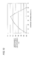
- FIG. 12 is a view illustrating a relationship between a vertex angle ⁇ of the directivity conversion pattern and the improvement rate of light use efficiency of the light guide plate;
- FIG. 13 is a view illustrating a relationship between an average opening angle of the directivity conversion pattern and the improvement rate of light use efficiency
- FIG. 14 is a view illustrating the average opening angle of the directivity conversion pattern
- FIGS. 15A to 15E are sectional views illustrating shapes in a section parallel to the light incident surface in each of different directivity conversion patterns
- FIGS. 16A to 16D are schematic diagrams illustrating various shapes of pattern forming regions in each of which the directivity conversion pattern is formed;
- FIG. 17 is a plan view illustrating a surface light source device according to a modification of the first embodiment of the present invention.
- FIG. 18 is a perspective view illustrating a surface light source device according to another modification of the first embodiment of the present invention.
- FIG. 19 is a perspective view illustrating a surface light source device according to a second embodiment of the present invention.
- FIG. 20 is a plan view of the surface light source device in FIG. 19 ;
- FIG. 21 is a sectional view illustrating a shape of a directivity conversion pattern in a section parallel to a light incident surface and a part thereof in an enlarged form;
- FIGS. 22A to 22C are schematic diagrams illustrating various shapes of pattern forming regions in each of which the directivity conversion pattern is formed;
- FIG. 23 is a perspective view illustrating a surface light source device according to a third embodiment of the present invention.
- FIG. 24A is a plan view of the surface light source device in FIG. 23 ;
- FIG. 24B is a sectional view taken along line Y-Y in FIG. 24A , and illustrates a cross sectional shape of a light diffusion pattern
- FIG. 25 is a perspective view illustrating a surface light source device according to a modification of the third embodiment of the present invention.
- FIG. 26 is a plan view illustrating a surface light source device according to a fourth embodiment of the present invention.
- FIG. 27 is an enlarged perspective view illustrating a part of a light introduction part in the surface light source device in FIG. 26 in an enlarged form;
- FIG. 28 is a perspective view illustrating a surface light source device according to a fifth embodiment of the present invention.
- FIG. 29 is a perspective view illustrating a surface light source device according to a modification of the fifth embodiment of the present invention.
- FIGS. 30A to 30C are schematic side views illustrating various modes of light guide plates
- FIGS. 31A to 31C are schematic side views illustrating various modes of light guide plates
- FIGS. 32A to 32C are schematic side views illustrating various modes of light guide plates
- FIGS. 33A to 33C are schematic side views illustrating various modes of light guide plates
- FIG. 34 is a plan view illustrating a surface light source device according to a sixth embodiment of the present invention.
- FIGS. 35A , 35 B, and 35 C are a side view, a plan view, and a bottom view illustrating a surface light source device according to a seventh embodiment of the present invention.
- FIG. 36 is a sectional view illustrating a liquid crystal display device according to an eighth embodiment of the present invention.
- FIG. 3 is a perspective view illustrating the surface light source device 31 of the first embodiment
- FIG. 4A is a plan view of the surface light source device 31
- FIG. 4B is a sectional view taken along line X-X in FIG. 4A , and illustrates a section of a lenticular lens 36 provided in a surface of a light guide plate 33
- FIG. 5 is a schematic sectional view along a longitudinal direction (a direction perpendicular to a light incident surface 38 ) of the surface light source device 31 , and illustrates a behavior of a ray in the light guide plate 33 .
- FIG. 3 is a perspective view illustrating the surface light source device 31 of the first embodiment
- FIG. 4A is a plan view of the surface light source device 31
- FIG. 4B is a sectional view taken along line X-X in FIG. 4A , and illustrates a section of a lenticular lens 36 provided in a surface of a light guide plate 33
- FIG. 5 is a schematic
- FIG. 6 is a view illustrating a section of a directivity conversion pattern 40 in a section parallel to the light incident surface 38 of the light guide plate 33 , and also illustrates a part of the directivity conversion pattern 40 in an enlarged form.
- FIGS. 7A and 7B illustrate behaviors of light reflected by the directivity conversion pattern.
- the surface light source device 31 includes a point light source 32 (a light source) and a light guide plate 33 .
- the point light source 32 is provided with one or a plurality of LEDs, and emits white light.
- an LED 41 is sealed in a transparent sealing resin 42 , the transparent sealing resin 42 is covered with a white resin 43 except for a front surface, and the front surface exposed from the white resin 43 of the transparent sealing resin 42 constitutes a light exit window 44 (an emission surface).
- the point light source 32 is smaller than a width of the light guide plate 33 , and the point light source 32 is called a point light source whereas a cold-cathode tube is called a linear light source.
- a light introduction part 35 is provided in an end surface of a thin-plate-like light guide plate body 34 so as to be continuously joined to the light guide plate body 34 .
- the light guide plate 33 is integrally formed using high-refractive-index transparent resins, such as an acrylic resin, a polycarbonate resin (PC), a cycloolefin-based material, and polymethylmethacrylate (PMMA).
- the light introduction part 35 is a thick, substantially wedge-shaped portion in the light guide plate 33 , and the point light source 32 is disposed so as to face a part of the light incident surface 38 that is the end surface of the light introduction part 35 .
- a thickness T of the end surface of the light introduction part 35 is equal to or greater than a height H of the light exit window 44 , and therefore the light emitted from the point light source 32 is efficiently incident from the light incident surface 38 to the light introduction part 35 to enhance the light use efficiency of the surface light source device 31 .
- An inclined surface 37 is formed in an upper surface (a surface on the same side as a light exit surface 39 of the light guide plate body 34 ) of the light introduction part 35 .
- the inclined surface 37 is inclined from the portion having the maximum thickness near the light incident surface 38 toward an end of the light guide plate body 34 .
- the band-like inclined surface 37 extends from one side edge of the light guide plate 33 to the other side edge. In the surface light source device 31 of the first embodiment, the inclined surface 37 is smoothly formed.
- the light guide plate body 34 constitutes most part of the light guide plate 33 .
- a thickness t of the light guide plate body 34 is smaller than the maximum thickness T of the light introduction part 35 , thereby achieving the low profile of the light guide plate 33 .
- the light guide plate body 34 has a flat-plate shape in which the surface and the rear surface are parallel to each other, and the light guide plate body 34 has a substantially even thickness. As illustrated in FIG. 4A , most part of the light guide plate body 34 constitutes an effective lighting region 46 , and an end-portion region adjacent to the light introduction part 35 constitutes a pattern forming region 47 .
- the effective lighting region 46 is a region from which the light having even luminance is output, and the effective lighting region 46 corresponds to a display region of the liquid crystal panel stacked on the surface light source device 31 .
- the upper surface of the effective lighting region 46 constitutes the light exit surface 39
- the lenticular lens 36 is molded in the light exit surface 39 of the effective lighting region 46 .
- convex lenses are laterally arranged while extending in parallel to a longitudinal direction of the light guide plate body 34 , and the lens surface is arranged in a width direction.
- the lenticular lens laterally spreads a directional pattern of the light output from the light exit surface 39 .
- a light exit part 45 is provided in an opposite surface (a lower surface) of the light exit surface 39 in the effective lighting region 46 .
- a triangular groove pattern is illustrated as the light exit part 45 .
- a pattern formed by sandblasting, a pattern formed by photographic printing using diffusion ink, a diffraction grating pattern, and any irregular pattern may be used as the light exit part 45 .
- the light exit part 45 may be provided in the light exit surface 39 of the light guide plate body 34 or in both the light exit surface 39 and the opposite surface thereof.
- the pattern forming region 47 is located in the end portion of the light guide plate body 34 , and is a belt-like region located between the end (the lower end of the inclined surface 37 ) of the light introduction part 35 and the end of the effective lighting region 46 .
- the directivity conversion pattern 40 is provided in the upper surface and/or the lower surface of the pattern forming region 47 . As illustrated in FIGS. 4A and 6 , a plurality of pattern elements 40 a having V-groove shapes are radially arranged in the directivity conversion pattern 40 .
- each pattern element 40 a When viewed in the direction perpendicular to the light exit surface 39 , each pattern element 40 a passes through an emission center of the point light source 32 , and is inclined with respect to a virtual straight line (hereinafter referred to as an optical axis C of the point light source 32 ) perpendicular to the light incident surface 38 , and the inclined directions of the pattern elements 40 a are opposite to each other with respect to both the sides of the optical axis C.
- an angle with the optical axis C increases gradually with increasing distance from the optical axis C.
- each pattern element 40 a is constructed by two slopes in which both inclined angles and inclined directions differ from each other in the cross section parallel to the light incident surface 38 , and the pattern element 40 a has an asymmetric V-groove shape. Accordingly, slopes having the different inclined directions are alternately arranged in the directivity conversion pattern 40 .
- the cross sectional shape of the directivity conversion pattern 40 has the following feature.
- a sum of widths D 2 of slopes 50 b in each of which the normal line N is inclined to an opposite side of a perpendicular line C′ orthogonal to the optical axis C is larger than a sum of widths D 1 of slopes 50 a in each of which the normal line N is inclined to the side of the perpendicular line C′.
- each of the sum of the widths D 2 of the slopes 50 b and the sum of the widths D 1 of the slopes 50 a is individually calculated in the right region and the left region of the optical axis C, and the sum of the widths D 2 of the slopes 50 b is larger than the sum of the widths D 1 of the slopes 50 a on both the sides of the optical axis C.
- the sum of the widths D 2 of the slopes 50 b is larger than the sum of the widths D 1 of the slopes 50 a on both the sides of the optical axis C.
- the width D 2 of the slope 50 b in which the normal line N is inclined to the opposite side of the perpendicular line C′ is larger than the width D 1 of the slope 50 a in which the normal line N is inclined to the side of the perpendicular line C′ for the two slopes 50 a and 50 b that are adjacent to each other at any point.
- the feature of the cross sectional shape of the directivity conversion pattern 40 can also be expressed as follows.
- An average angle of angles ⁇ (or the inclined angles of the slopes 50 a ) each of which is formed by the perpendicular line C′ and the normal line N of the slope 50 a inclined to the side of the perpendicular line C′ is larger than an average angle of angles ⁇ (or the inclined angles of the slopes 50 b ) each of which is formed by the perpendicular line C′ and the normal line N of the slope 50 b inclined to the side of the perpendicular line C′.
- the average angle of the angles ⁇ each of which is formed by the perpendicular line C′ and the normal line N of the slope 50 a inclined to the side of the perpendicular line C′ is defined by ⁇ i ⁇ D 1 i/ ⁇ D 1 i (see FIG. 14 ).
- ⁇ i is an angle formed by the perpendicular line C′ and the normal line N of the slope 50 a inclined to the side of the perpendicular line C′
- D 1 i is a width of each slope 50 a (i is an index added to each slope 50 a ).
- the sums of a denominator and a numerator are calculated with respect to the slope 50 a in the right or left region of the optical axis C.
- the average angle of the angles ⁇ each of which is formed by the perpendicular line C′ and the normal line N of the slope 50 b inclined to the opposite side of the perpendicular line C′ is defined by ⁇ j ⁇ D 2 j/ ⁇ D 2 j (see FIG. 14 ).
- ⁇ j is an angle formed by the perpendicular line C′ and the normal line N of the slope 50 b inclined to the opposite side of the perpendicular line C′
- D 2 j is a width of each slope 50 b (j is an index added to each slope 50 b ).
- the sums of a denominator and a numerator are calculated with respect to the slope 50 b in the right or left region of the optical axis C.
- the magnitudes of the average angles are compared to each other in each of the right and left regions of the optical axis C.
- the angle ⁇ formed by the perpendicular line C′ and the normal line N of the slope 50 a inclined to the side of the perpendicular line C′ is larger than the angle ⁇ formed by the perpendicular line C′ and the normal line N inclined to the opposite side of the perpendicular line C′.
- optical patterns such as the lenticular lens 36 and the directivity conversion pattern 40 , are coarsely drawn for the sake of convenience. However, actually the optical patterns are finely formed with micrometer accuracy.
- the light emitted from the point light source 32 is incident through the light incident surface 38 to the light introduction part 35 , the light is reflected by the upper or lower surface of the light introduction part 35 or passes through the light introduction part 35 , and the light is introduced to the thin light guide plate body 34 .
- the light introduced to the light guide plate body 34 is guided in the light guide plate body 34 while being reflected by the directivity conversion pattern 40 , the lenticular lens 36 , and the lower surface of the light guide plate body 34 . Then, the light is reflected or diffused by the light exit part 45 , and substantially evenly output from the light exit surface 39 .
- FIGS. 7A and 7B are views illustrating behaviors of the light L 2 reflected by the directivity conversion pattern 40 , where FIG. 7A is a view illustrating the behavior of the light L 2 when the light guide plate 33 is viewed from above, and FIG. 7B is a view illustrating the behavior of the light L 2 when the light L 2 is viewed in the direction perpendicular to the light incident surface 38 (from the point light source side).
- the pattern element 40 a is disposed in parallel with the optical axis C, because light L 1 reflected by the slope 50 b is laterally spread, the light L 1 may leak from the side surface of the light guide plate 33 or the lenticular lens 36 .
- the directivity conversion pattern 40 is disposed so as to be oblique to the optical axis C. Therefore, the light L 2 is reflected by the slope 50 b of the pattern element 40 a so as to come close to the direction parallel to the optical axis C when viewed from above, and the light L 2 is oriented forward.
- the light reflected by the pattern element 40 a hardly reaches the side surface of the light guide plate 33 , and is hardly incident to the lenticular lens 36 from the lateral direction. Therefore, the leakage of the light from the side surface of the light guide plate 33 or the lenticular lens 36 can be reduced to enhance the light use efficiency, and the luminance of the surface light source device 31 can be improved.
- an angle formed by the pattern element 40 a and the optical axis C increases with increasing distance from the optical axis C.
- the angle with the length direction of the pattern element 40 a increases with increasing distance from the optical axis C. Accordingly, the angle formed by the pattern element 40 a and the optical axis C is increased with increasing distance from the optical axis C, which allows the light to be bent forward irrespective of the distance from the optical axis C.
- the light reflected by the directivity conversion pattern 40 is not entirely bent in the direction parallel to the optical axis C.
- the whole directional pattern of the light reflected by the directivity conversion pattern 40 particularly a maximum luminance direction of the light is converted so as to be oriented toward the direction parallel to the optical axis C.
- FIG. 8A is a view illustrating light guide directivity viewed from the direction perpendicular to the light incident surface of the light guide plate 13 in the case where the directivity conversion pattern is not provided in the light guide plate body 14 (the conventional example in FIG. 1 ).
- FIG. 8B is a view illustrating the light guide directivity viewed from the direction perpendicular to the light incident surface 38 of the light guide plate 33 in the case where the directivity conversion pattern 40 is provided in the light guide plate body 34 (the first embodiment).
- R 1 indicates a spherical surface having a radius of 1 and R 2 indicates a circle, which is formed such that a circular cone having the same angle as a critical angle arcsin(1/n) [where n is a refractive index of the light guide plate] of reflection with respect to the optical axis C intersects with the spherical surface R 1 .
- the light guide directivity (the directional pattern) is described in detail in WO 2010/070821 and WO 2008/153024.
- directivity 51 indicates the directional pattern of the light immediately after the light is incident to the light introduction parts 15 and 35 .
- directivity 52 indicates the directional pattern of the light reflected by the inclined surface 17 of the light introduction part 15 .
- directivity 52 indicates the directional pattern of the light, which is reflected by the inclined surface 37 of the light introduction part 35 and further reflected by the directivity conversion pattern 40 .
- the directivity conversion pattern 40 reflects the light to pull the directivity 52 inward. Therefore, as indicated by the hatching in FIG. 8B , the amount of light spreading out from the circle R 2 decreases, and the leakage of light from the light guide plate 33 is reduced.
- the sum of the widths of the slopes 50 b in each of which the normal line is inclined to the opposite side of the perpendicular line C′ in the directivity conversion pattern 40 is larger than the sum of the widths of the slopes 50 a in each of which the normal line is inclined to the side of the perpendicular line C′. Therefore, an area of the surface (the slope 50 b ), which reflects the light toward the direction parallel to the optical axis C as illustrated in FIG. 7 , can be enlarged to enhance the effect that the directional pattern of the light is converted to the direction parallel to the optical axis C.
- FIG. 9 is a view illustrating a relationship between (sum of widths of outward normal lines)/(sum of widths of outward normal lines+sum of widths of inward normal lines) of the directivity conversion pattern and an improvement rate of light use efficiency.
- the outward normal line refers to the normal line N that is inclined to the opposite side of the perpendicular line C′ orthogonal to the optical axis C.
- the width of the outward normal line refers to the width D 2 of the slope 50 b having the outward normal line.
- the inward normal line refers to the normal line N that is inclined to the side of the perpendicular line C′ orthogonal to the optical axis C.
- the width of the inward normal line refers to the width D 1 of the slope 50 a having the inward normal line.
- the sum of the widths of the outward normal lines is obtained by adding widths D 21 , D 22 , . . . of the outward normal lines, namely, D 21 +D 22 + . . . in one of the right and left regions of the optical axis C.
- the sum of the widths of the inward normal lines is obtained by adding widths D 11 , D 12 , . . . of the inward normal lines, namely, D 11 +D 12 + . . . in one of the right and left regions of the optical axis C.
- the high effect to improve the light use efficiency is obtained, when (sum of widths of outward normal lines)/(sum of widths of outward normal lines+sum of widths of inward normal lines) is greater than or equal to 0.5, namely, when the sum of the widths of the outward normal lines is greater than the sum of the widths of the inward normal lines.
- the highest effect is obtained when (sum of widths of outward normal lines)/(sum of widths of outward normal lines+sum of widths of inward normal lines) is 0.75.
- FIG. 10 is a view illustrating a relationship between (average angle of outward normal lines)/(average angle of outward normal lines+average angle of inward normal lines) of the directivity conversion pattern and the improvement rate of light use efficiency.
- the average angle of the outward normal lines is defined by ( ⁇ 1 ⁇ D 21+ ⁇ 2 ⁇ D 22+ . . . )/( D 21 +D 22+ . . . ) where ⁇ 1 , ⁇ 2 , . . . are angles each of which is formed by the outward normal line and the perpendicular line C′ in the cross section parallel to the light incident surface 38 and in one of the right and left regions of the optical axis C, and D 21 , D 22 , .
- the average angle of the inward normal lines is defined by ( ⁇ 1 ⁇ D 11+ ⁇ 2 ⁇ D 12+ . . . )/( D 11 +D 12+ . . . ) where ⁇ 1 , ⁇ 2 , . . . are angles each of which is formed by the inward normal line and the perpendicular line C′ in the cross section parallel to the light incident surface 38 and in one of the right and left regions of the optical axis C, and D 11 , D 12 , . . . are widths of the slopes having the inward normal lines.
- the vertex angle ⁇ (see FIG. 6 ) formed by the pattern elements 40 a adjacent to each other in the directivity conversion pattern 40 ranges from 50° to 140°.
- FIG. 12 illustrates a simulation result showing this reason. Referring to FIG. 12 , how much the light use efficiency changes is examined when the vertex angle is changed in the range of 15° to 170° in the directivity conversion pattern 40 having the shape in FIG. 6 .
- a horizontal axis indicates the vertex angle ⁇ of the directivity conversion pattern 40
- a vertical axis indicates an improvement rate of light use efficiency.
- the improvement rate of light use efficiency indicates a ratio of the light output from the light exit surface 39 in the light incident from the light incident surface 38 , and the improvement rate of light use efficiency is expressed based on the light use efficiency (100%) of the conventional example in FIG. 1 .
- the effect to improve the light use efficiency is recognized in the substantially whole region where the vertex angle ⁇ of the directivity conversion pattern 40 is less than or equal to 180°, and the highest effect is obtained at the vertex angle ⁇ of 90°.
- the directivity conversion pattern 40 is of practical value because the effect to improve the light use efficiency is obtained by at least 2% when the vertex angle ⁇ ranges from 50° to 140°. Therefore, the vertex angle ⁇ of the directivity conversion pattern 40 desirably ranges from 50° to 140°.
- FIG. 13 illustrates a simulation result of a relationship between an average opening angle of the directivity conversion pattern 40 having the shape in FIG. 6 and the improvement rate of light use efficiency.
- the average opening angle of the directivity conversion pattern 40 is obtained by an arithmetic average of inclinations ⁇ 1 , ⁇ 2 , ⁇ 3 , . . . , each of which is formed by the extending direction of the pattern elements 40 a and the optical axis C in the right or left region when the directivity conversion pattern 40 viewed in the direction perpendicular to the light exit surface 39 of the light guide plate 33 is divided into the right and left regions with respect to the optical axis C.
- FIG. 14 illustrates a simulation result of a relationship between an average opening angle of the directivity conversion pattern 40 having the shape in FIG. 6 and the improvement rate of light use efficiency.
- the average opening angle of the directivity conversion pattern 40 is obtained by an arithmetic average of inclinations ⁇ 1 , ⁇ 2 , ⁇ 3 , .
- the effect to improve the light use efficiency is obtained when the average opening angle of the directivity conversion pattern 40 is less than or equal to 60°.
- the directivity conversion pattern 40 is of practical value, because the improvement rate of light use efficiency is obtained by at least 2% when the average opening angle ranges from 5° to 55°. Therefore, the average opening angle of the directivity conversion pattern 40 desirably ranges from 5° to 55°.
- the pattern elements 40 a having asymmetric sectional shapes may repeatedly be arranged in the right and left regions.
- the pattern elements 40 a having asymmetric sectional shapes are arranged in the right and left regions while gradually deformed.
- the pattern elements 40 a having symmetric V-groove sectional shapes may repeatedly be arranged.
- a vertex portion of the directivity conversion pattern 40 may be curved as illustrated in FIG. 15D , or the pattern elements 40 a having polygonal sectional shapes may be arranged as illustrated in FIG. 15E .
- the region (the pattern forming region 47 ) where the directivity conversion pattern 40 is provided there are various shapes of the region (the pattern forming region 47 ) where the directivity conversion pattern 40 is provided.
- the directivity conversion pattern 40 may not be provided at a corner on the point light source side where the light of the point light source 32 hardly reaches.
- the region where the directivity conversion pattern 40 does not exist may be enlarged to form the trapezoidal pattern forming region 47 .
- FIG. 16C in the pattern forming region 47 , an edge located on the opposite side of the point light source 32 is projected to the opposite side of the point light source 32 .
- the edge located on the opposite side of the point light source 32 may be recessed to the point light source side.
- FIG. 17 is a plan view illustrating a surface light source device 48 according to a modification of the first embodiment of the present invention.
- the pattern elements 40 a of the directivity conversion pattern 40 may be parallel to one another on both the sides of the optical axis C of the point light source 32 . That is, in a surface light source device 48 , the pattern elements 40 a of the directivity conversion pattern 40 are inclined so as to be oppositely oriented with respect to the optical axis C on both the sides of the optical axis C of the point light source 32 .
- the pattern elements 40 a are parallel to one another in a right half of the optical axis C, and the pattern elements 40 a are parallel to one another in a left half.
- the leakage of the light can be reduced because the directional pattern of the light reflected by the directivity conversion pattern 40 can be converted to the direction parallel to the optical axis C.
- the directivity conversion pattern 40 is easily produced.
- a molding die is easily produced when a reversal pattern for molding the directivity conversion pattern 40 is formed in the molding die by cutting.
- FIG. 18 is a perspective view illustrating a surface light source device 49 according to another modification of the first embodiment of the present invention.
- the lenticular lens 36 may be eliminated, and the light exit surface 39 of the effective lighting region 46 may be smooth. Even if the lenticular lens 36 is eliminated, the leakage of the light from the side surface can be advantageously reduced.
- FIG. 19 is a perspective view illustrating a surface light source device 61 according to a second embodiment of the present invention.
- FIG. 20 is a plan view of the surface light source device 61 .
- FIG. 21 illustrates a cross sectional shape of the directivity conversion pattern 40 in the cross section parallel to the light incident surface 38 .
- FIG. 21 also illustrates a part of the directivity conversion pattern 40 in an enlarged form.
- the directivity conversion pattern 40 is partially removed to form a flat surface 62 in proximity to the optical axis C of the point light source 32 .
- the triangular flat surface 62 is provided so as to be sandwiched between the right and left directivity conversion patterns 40 .
- the leakage of the light from the side surface of the light guide plate 33 or the lenticular lens 36 can be reduced by the directivity conversion patterns 40 located on both the sides. Additionally, since the directivity conversion pattern 40 is partially removed in front of the point light source 32 , the amount of light sent to the front of the point light source 32 can be increased as indicated by broken lines in FIG. 20 . The light is laterally spread by the directivity conversion pattern 40 to decrease the amount of light sent to the front of the point light source 32 , which allows prevention of darkness in a portion located in front of the point light source 32 .
- a shape of the portion in which the directivity conversion pattern 40 is removed is not limited to the triangular shape as illustrated in FIGS. 19 and 20 .
- the pentagonal directivity conversion pattern 40 may be removed as illustrated in FIG. 22A
- the rectangular directivity conversion pattern 40 may be removed as illustrated in FIG. 22B
- the trapezoidal directivity conversion pattern 40 may be removed as illustrated in FIG. 22C .
- FIG. 23 is a perspective view illustrating a surface light source device 71 according to a third embodiment of the present invention.
- FIG. 24A is a plan view of the surface light source device 71 .
- FIG. 24B is a sectional view taken along line Y-Y in FIG. 24A .
- a light diffusion pattern 72 which laterally spreads the directivity of the reflected light, is formed in the upper surface and/or the lower surface of the light introduction part 35 .
- the light diffusion pattern 72 may be formed by arranging vertically extending V-grooves 72 a in parallel with one another, or the light diffusion pattern 72 may be a pattern having a lenticular-lens shape or a random shape.
- the light is sent to the side surface direction of the light guide plate 33 while being laterally spread by the light diffusion pattern 72 , thereby preventing darkening of a side edge portion of the light exit surface 39 .
- the directional pattern of the light sent to the side surface direction is converted to the direction parallel to the optical axis C by the directivity conversion pattern 40 , so that the light hardly leaks from the side surface of the light guide plate 33 or the lenticular lens 36 .
- the flat surface 62 having no directivity conversion pattern 40 is formed in front of the point light source 32 to prevent darkening in front of the point light source 32 .
- the light diffusion pattern 72 is constructed by the V-grooves 72 a , the light hardly leaks from the inclined surface 37 or the light introduction part 35 , and the light, which is emitted from the point light source 32 and incident to the light introduction part 35 , can be introduced to the light guide plate body 34 at a low loss.
- the ratio of the amount of light leaking from the light guide plate 33 was 5%, when a sample was produced while dimensions of each part in FIG. 23 were set as follows.
- width W of light guide plate 33 5.5 mm
- refractive index n of light guide plate 33 1.59
- the ratio of the amount of leakage light was 15%, when the surface light source device of the conventional example in FIG. 1 was produced on the same condition while the directivity conversion pattern 40 and the light diffusion pattern 72 are removed. Therefore, in the surface light source device of the third embodiment, the ratio of the leakage light can be reduced to 1 ⁇ 3 of the conventional example.
- FIG. 25 is a perspective view illustrating a surface light source device 73 according to a modification of the third embodiment of the present invention.
- the light diffusion pattern 72 which laterally spreads the light is radially formed.
- FIG. 26 is a plan view illustrating a surface light source device 81 according to a fourth embodiment of the present invention.
- FIG. 27 is a perspective view illustrating a part of the light introduction part 35 in the surface light source device 81 in an enlarged form.
- a light diffusion pattern 82 which laterally spreads the light is provided in at least a region facing the point light source 32 in the light incident surface 38 of the light introduction part 35 .
- the light diffusion pattern 82 may be formed into a cylindrical-lens shape in which convex lenses extending in the height direction are laterally arranged, the light diffusion pattern 82 may be constructed by arranging the V-grooves extending in the height direction in parallel with one another, or the light diffusion pattern 82 may be a pattern having a random shape.
- the light is sent to the side surface direction of the light guide plate 33 while being laterally spread by the light diffusion pattern 82 , thereby preventing darkening of the side edge portion of the light exit surface 39 .
- the directional pattern of the light sent to the side surface direction is converted to the direction parallel to the optical axis C by the directivity conversion pattern 40 , whereby the light hardly leaks from the side surface of the light guide plate 33 or the lenticular lens 36 .
- the flat surface 62 having no directivity conversion pattern 40 is formed in front of the point light source 32 so that darkening in front of the point light source 32 is prevented.
- FIG. 28 is a perspective view illustrating a surface light source device 91 according to a fifth embodiment of the present invention.
- a projection part 92 is formed in the inclined surface 37 of the light introduction part 35 .
- the projection part 92 has the same shape as a part of a truncated cone.
- the point light source 32 is surrounded by an outer peripheral surface (inclined surface) of the projection part 92 in a substantial arc when the light guide plate 33 is viewed from above. Therefore, the light, which is emitted from the point light source 32 and enters the light introduction part 35 from the light incident surface 38 , is substantially perpendicularly incident to the outer peripheral surface of the projection part 92 .
- the light hardly leaks from the inclined surface (the outer peripheral surface of the projection part 92 ) of the light introduction part 35 , and efficiency of the light guide from the light introduction part 35 to the light guide plate body 34 is improved.
- a light diffusion pattern 93 which laterally spreads the light may be provided in the outer peripheral surface of the projection part 92 .
- FIGS. 30A to 30C , 31 A to 31 C, 32 A to 32 C, and 33 A to 33 C are schematic side views illustrating various shapes of the light guide plates 33 .
- the effect of the prevent invention can be obtained when these light guide plates are used.
- the inclined surface 37 of the light introduction part 35 is started from the light incident surface 38 .
- the inclined surfaces 37 of the light introduction part 35 are provided at a plurality of stages.
- the inclined surface 37 of the light introduction part 35 is formed into a curved shape.
- the upper surface of the light guide plate body 34 is inclined to form the tapered light guide plate body 34 .
- the end on the side of the light incident surface 38 in the upper surface of the light introduction part 35 is inclined toward the opposite direction of the inclined surface 37 to form an inversely inclined part 95 .
- the inversely inclined part 95 is provided, whereby a height T′ at the end of the light introduction part 35 is smaller than a thickness t of the light guide plate body 34 .
- the inclined surfaces 37 are provided in the upper and lower surfaces of the light introduction part 35 , and the light diffusion pattern 72 is provided in one or both of the inclined surfaces 37 .
- a portion 96 thicker than the light introduction part 35 may be provided in a part of the light guide plate body 34 .
- a moderately inclined surface 97 may be provided by moderately inclining an uppermost surface of the light introduction part 35 .
- the light diffusion patterns 72 are provided in both the inclined surface 37 and the lower surface of the light introduction part 35 .
- the light diffusion pattern 72 is provided only in the lower surface of the light introduction part 35 .
- the light diffusion pattern 72 provided in the lower surface of the light introduction part 35 may extend to the lower surface of the light guide plate body 34 .
- the inclined surface 37 is formed at two stages while the inclination is changed in the middle of the slope.
- the light diffusion pattern 72 is provided in the whole inclined surface 37 .
- the light diffusion pattern 72 is provided only in a lower half of the inclined surface 37 .
- one light source is used.
- a plurality of point light sources may be arranged while facing the light incident surface of the light guide plate.
- the directivity conversion pattern having the above configuration may repeatedly be provided in the position corresponding to the point light source at the same interval as the point light source.
- the directivity conversion pattern is provided in the upper surface of the light guide plate.
- the directivity conversion pattern may be provided in the lower surface of the light guide plate, or the directivity conversion pattern may be provided in both the upper surface and the lower surface of the light guide plate.
- FIG. 34 is a plan view illustrating the surface light source device 101 in which the plurality of point light sources 32 are disposed facing the light incident surface 38 of the light guide plate 33 .
- the directivity conversion patterns 40 are provided at the same interval as an interval P between the point light sources 32 with the midpoint between the point light sources 32 as a boundary.
- the point light sources 32 have the interval P of 5.5 mm
- the directivity conversion patterns 40 have the same interval of 5.5 mm.
- the light may reach the middle portion between the point light sources 32 from the point light sources 32 on both the sides.
- the directivity conversion pattern 40 cannot be optimally designed such that the leakage of the light is not generated. Therefore, the light use efficiency of the surface light source device is degraded.
- the light from the plurality of point light sources 32 is preferably not incident to the directivity conversion pattern 40 .
- an incident angle ⁇ of the light which is emitted from the point light source 32 to enter the light introduction part 35 from the light incident surface 38 , is expressed as follows.
- ⁇ arcsin(1 /n ) (Equation 1)
- n is a refractive index of the light guide plate 33 . Therefore, as illustrated in FIG. 34 , the spread of the light in the light introduction part 35 falls within a range of 2 ⁇ around a light source center C. From FIG. 34 and Equation 1, a horizontal spread g of the light in the directivity conversion pattern 40 is expressed as follows.
- the directivity conversion pattern 40 can optimally be designed when the distance S from the end surface of the point light source 32 to the end of the directivity conversion pattern 40 is determined so as to satisfy the condition of S ⁇ P /[2 ⁇ arcsin(1 /n )] and the leakage of the light can be reduced to enhance the light use efficiency.
- the interval P between the point light sources 32 is set to 5.5 mm and that the refractive index n of the light guide plate 33 is set to 1.59 (polycarbonate resin)
- J ⁇ about 4 mm is obtained, and the length of the region provided with the directivity conversion pattern 40 may be less than or equal to about 4 mm.
- FIGS. 35A , 35 B, and 35 C are a side view, a plan view, and a bottom view illustrating a surface light source device 111 according to a seventh embodiment of the present invention.
- the lenticular lens 36 is provided in an effective lighting region in the upper surface of the light guide plate body 34
- the end portion in the lower surface of the light guide plate body 34 is used as the pattern forming region 47
- the directivity conversion pattern 40 is provided in the end portion in the lower surface of the light guide plate body 34 .
- the directivity conversion pattern 40 may be provided in the surface on the side opposite from the light exit surface 39 of the light guide plate 33 .
- FIG. 36 is a schematic sectional view illustrating a liquid crystal display device 121 in which the surface light source device (for example, the surface light source device 31 of the first embodiment) of the present invention is used.
- the surface light source device for example, the surface light source device 31 of the first embodiment
- a diffuser plate 122 , a prism sheet 123 , and a liquid crystal panel 124 are stacked while facing the light exit surface side of the light guide plate 33 , and a reflecting sheet 125 is disposed on the rear surface side of the light guide plate 33 .
- the feature of the surface light source device of the present invention can be utilized, the light use efficiency of the liquid crystal display device 121 can be enhanced to facilitate visualization of the screen, and the low profile of the liquid crystal display device 121 can be achieved.
Landscapes
- Physics & Mathematics (AREA)
- General Physics & Mathematics (AREA)
- Optics & Photonics (AREA)
- Planar Illumination Modules (AREA)
- Liquid Crystal (AREA)
Abstract
Description
P/[2·arcsin(1/n)]
from an end surface on a light exit side of the light source, where n is a refractive index of the light guide plate. This is because, when the region where the directivity conversion pattern is formed extends beyond P/[2·arcsin(1/n)] from the end surface on the light exit side of the light source, the light emitted from a certain light source enters the region in front of the adjacent light source to decrease the light use efficiency.
Σαi×D1i/ΣD1i
(see
Σβj×D2j/ΣD2j
(see
(β1×D21+β2×D22+ . . . )/(D21+D22+ . . . )
where β1, β2, . . . are angles each of which is formed by the outward normal line and the perpendicular line C′ in the cross section parallel to the
(α1×D11+α2×D12+ . . . )/(D11+D12+ . . . )
where α1, α2, . . . are angles each of which is formed by the inward normal line and the perpendicular line C′ in the cross section parallel to the
γ=arcsin(1/n) (Equation 1)
Herein, n is a refractive index of the
g=S tan γ≈S·γ≈S·arcsin(1/n) (Equation 2)
In order that the light guided in the direction of γ from the light source center C does not enter the adjacent region, it is necessary that the horizontal spread g be smaller than ½ of the interval P between the point
g≦P/2 (Condition 1)
Herein, S is a distance from the end surface (the emission surface) of the point
S≦P/[2·arcsin(1/n)] (Condition 2)
S≦P/[2−arcsin(1/n)]
and the leakage of the light can be reduced to enhance the light use efficiency. For example, assuming that the interval P between the point
J≦about 4 mm
is obtained, and the length of the region provided with the
Claims (17)
P/[2·arcsin(1/n)]
Applications Claiming Priority (3)
| Application Number | Priority Date | Filing Date | Title |
|---|---|---|---|
| JP2012-059419 | 2012-03-15 | ||
| JP2012059419A JP5556837B2 (en) | 2012-03-15 | 2012-03-15 | Surface light source device and liquid crystal display device |
| JPJP2012-059419 | 2012-03-15 |
Publications (2)
| Publication Number | Publication Date |
|---|---|
| US20130242231A1 US20130242231A1 (en) | 2013-09-19 |
| US9075171B2 true US9075171B2 (en) | 2015-07-07 |
Family
ID=49133037
Family Applications (1)
| Application Number | Title | Priority Date | Filing Date |
|---|---|---|---|
| US13/775,960 Active 2033-07-07 US9075171B2 (en) | 2012-03-15 | 2013-02-25 | Surface light source device and liquid crystal display device |
Country Status (5)
| Country | Link |
|---|---|
| US (1) | US9075171B2 (en) |
| JP (1) | JP5556837B2 (en) |
| KR (2) | KR101413894B1 (en) |
| CN (1) | CN103307512B (en) |
| TW (1) | TWI504990B (en) |
Cited By (8)
| Publication number | Priority date | Publication date | Assignee | Title |
|---|---|---|---|---|
| US20140211125A1 (en) * | 2013-01-30 | 2014-07-31 | Omron Corporation | Light guide plate and surface illumination device |
| US20150185398A1 (en) * | 2014-01-02 | 2015-07-02 | Radiant Opto-Electronics Corporation | Light guide plate |
| US20150355402A1 (en) * | 2012-03-16 | 2015-12-10 | Radiant Opto-Electronics Corporation | Light guide plate and light source module |
| US20160077270A1 (en) * | 2013-05-24 | 2016-03-17 | Sharp Kabushiki Kaisha | Lighting device and display device |
| US20160109639A1 (en) * | 2014-10-21 | 2016-04-21 | Omron Corporation | Light guide plate and surface illumination device |
| US9442240B2 (en) | 2012-03-16 | 2016-09-13 | Radiant Opto-Electronics Corporation | Light guide plate and light source module |
| US20170192166A1 (en) * | 2016-01-04 | 2017-07-06 | Young Lighting Technology Inc. | Light source module and display device |
| US20170285244A1 (en) * | 2016-04-04 | 2017-10-05 | Minebea Mitsumi Inc. | Planar illumination device |
Families Citing this family (48)
| Publication number | Priority date | Publication date | Assignee | Title |
|---|---|---|---|---|
| JP5532109B2 (en) * | 2012-11-15 | 2014-06-25 | オムロン株式会社 | Light guide plate and surface light source device |
| JP6245431B2 (en) * | 2012-12-26 | 2017-12-13 | オムロン株式会社 | Surface light source device and light guide plate thereof |
| JP6277650B2 (en) * | 2013-09-30 | 2018-02-14 | 大日本印刷株式会社 | Light guide plate, surface light source device, video source unit, and liquid crystal display device |
| TWI486652B (en) * | 2013-12-24 | 2015-06-01 | Chi Mei Corp | Optical plate and back light module using the same |
| KR102137968B1 (en) * | 2014-02-03 | 2020-07-29 | 삼성디스플레이 주식회사 | Light guide panel, backlight unit, display devece and method for manufacturing light guide panel |
| US11408572B2 (en) * | 2014-03-15 | 2022-08-09 | Ideal Industries Lighting Llc | Luminaires utilizing optical waveguide |
| JP6288442B2 (en) | 2014-04-09 | 2018-03-07 | オムロン株式会社 | Light guide plate and surface light source device |
| JP6288443B2 (en) * | 2014-04-10 | 2018-03-07 | オムロン株式会社 | Light guide plate and surface light source device |
| KR101677188B1 (en) * | 2014-06-20 | 2016-11-17 | 김태규 | Method for manufacturing the Light Guide Plate |
| CN104714271A (en) * | 2015-03-30 | 2015-06-17 | 深圳市华星光电技术有限公司 | Light guide plate and backlight module |
| US20160363711A1 (en) * | 2015-06-10 | 2016-12-15 | General Electric Company | Lighting system with improved illumination distribution and output luminance variation |
| KR102383149B1 (en) * | 2015-07-30 | 2022-04-06 | 엘지디스플레이 주식회사 | Light Guide Plate and Backlight Unit having the same |
| CN105093388A (en) * | 2015-08-07 | 2015-11-25 | 武汉华星光电技术有限公司 | Light guide plate and backlight module provided with same |
| EP3369034B1 (en) | 2015-10-26 | 2023-07-05 | RealD Spark, LLC | Intelligent privacy system, apparatus, and method thereof |
| CN105629370A (en) * | 2016-01-05 | 2016-06-01 | 京东方光科技有限公司 | Light guide plate, backlight module and display device |
| US11079619B2 (en) | 2016-05-19 | 2021-08-03 | Reald Spark, Llc | Wide angle imaging directional backlights |
| WO2018058423A1 (en) * | 2016-09-29 | 2018-04-05 | 瑞仪光电(苏州)有限公司 | Light guide plate, backlight module and display device |
| US10126575B1 (en) | 2017-05-08 | 2018-11-13 | Reald Spark, Llc | Optical stack for privacy display |
| CN110785694B (en) | 2017-05-08 | 2023-06-23 | 瑞尔D斯帕克有限责任公司 | Optical stack for directional display |
| TW201921060A (en) | 2017-09-15 | 2019-06-01 | 美商瑞爾D斯帕克有限責任公司 | Optical stack for switchable directional display |
| US10948648B2 (en) | 2017-09-29 | 2021-03-16 | Reald Spark, Llc | Backlights having stacked waveguide and optical components with different coefficients of friction |
| US11115647B2 (en) | 2017-11-06 | 2021-09-07 | Reald Spark, Llc | Privacy display apparatus |
| CN111868585B (en) | 2018-01-25 | 2022-11-15 | 瑞尔D斯帕克有限责任公司 | Reflective optical stack for privacy display device |
| KR20200120650A (en) | 2018-01-25 | 2020-10-21 | 리얼디 스파크, 엘엘씨 | Touch screen for privacy display |
| US10935714B2 (en) | 2018-03-22 | 2021-03-02 | Reald Spark, Llc | Optical waveguide for directional backlight |
| CN110500556B (en) * | 2018-05-18 | 2022-08-16 | 法雷奥照明湖北技术中心有限公司 | Light guide for a lamp, lamp for a motor vehicle and motor vehicle |
| EP3814680A4 (en) | 2018-06-29 | 2022-05-04 | RealD Spark, LLC | Optical stack for privacy display |
| US11073735B2 (en) | 2018-07-18 | 2021-07-27 | Reald Spark, Llc | Optical stack for switchable directional display |
| US11106103B2 (en) | 2018-10-03 | 2021-08-31 | Reald Spark, Llc | Privacy display apparatus controlled in response to environment of apparatus |
| CN113167953B (en) | 2018-11-07 | 2023-10-24 | 瑞尔D斯帕克有限责任公司 | Directional display device |
| US11287677B2 (en) | 2019-01-07 | 2022-03-29 | Reald Spark, Llc | Optical stack for privacy display |
| WO2020167680A1 (en) | 2019-02-12 | 2020-08-20 | Reald Spark, Llc | Diffuser for privacy display |
| CN110146951A (en) * | 2019-05-30 | 2019-08-20 | 开平市盈光机电科技有限公司 | A kind of reflective surface has the light guide plate of optical microstructures |
| TW202102883A (en) | 2019-07-02 | 2021-01-16 | 美商瑞爾D斯帕克有限責任公司 | Directional display apparatus |
| WO2021026018A1 (en) | 2019-08-02 | 2021-02-11 | Reald Spark, Llc | Optical stack for privacy display |
| US11114063B2 (en) | 2019-10-02 | 2021-09-07 | Reald Spark, Llc | Privacy display apparatus |
| US11099448B2 (en) | 2019-11-13 | 2021-08-24 | Reald Spark, Llc | Off-axis display device |
| WO2021118936A1 (en) | 2019-12-10 | 2021-06-17 | Reald Spark, Llc | Control of reflections of a display device |
| EP4078254B1 (en) | 2019-12-18 | 2024-09-25 | RealD Spark, LLC | Control of ambient light for a privacy display |
| WO2021222606A1 (en) | 2020-04-30 | 2021-11-04 | Reald Spark, Llc | Directional display apparatus |
| US11442316B2 (en) | 2020-04-30 | 2022-09-13 | Reald Spark, Llc | Directional display apparatus |
| WO2021222598A1 (en) | 2020-04-30 | 2021-11-04 | Reald Spark, Llc | Directional display apparatus |
| TW202204818A (en) | 2020-07-29 | 2022-02-01 | 美商瑞爾D斯帕克有限責任公司 | Pupillated illumination apparatus |
| CN116209945A (en) | 2020-07-29 | 2023-06-02 | 瑞尔D斯帕克有限责任公司 | Backlight for switchable directional display |
| JP7534167B2 (en) * | 2020-09-18 | 2024-08-14 | スタンレー電気株式会社 | Light guide plate, lighting device, display device |
| US11892717B2 (en) | 2021-09-30 | 2024-02-06 | Reald Spark, Llc | Marks for privacy display |
| US11977286B2 (en) | 2022-02-09 | 2024-05-07 | Reald Spark, Llc | Observer-tracked privacy display |
| WO2023196440A1 (en) | 2022-04-07 | 2023-10-12 | Reald Spark, Llc | Directional display apparatus |
Citations (4)
| Publication number | Priority date | Publication date | Assignee | Title |
|---|---|---|---|---|
| WO2008153024A1 (en) | 2007-06-12 | 2008-12-18 | Omron Corporation | Surface light source apparatus |
| WO2010070821A1 (en) | 2008-12-16 | 2010-06-24 | オムロン株式会社 | Planar light source device |
| US20110170036A1 (en) * | 2010-01-13 | 2011-07-14 | Omron Corporation | Area light source device and liquid crystal display device |
| US20110216267A1 (en) | 2010-03-05 | 2011-09-08 | Omron Corporation | Area light source device and liquid crystal display device |
Family Cites Families (5)
| Publication number | Priority date | Publication date | Assignee | Title |
|---|---|---|---|---|
| JP4145585B2 (en) * | 2002-07-05 | 2008-09-03 | 株式会社日立製作所 | Liquid crystal display |
| JP5315613B2 (en) * | 2006-01-31 | 2013-10-16 | コニカミノルタ株式会社 | Light guide plate and backlight device |
| US7740387B2 (en) * | 2006-05-24 | 2010-06-22 | 3M Innovative Properties Company | Backlight wedge with side mounted light source |
| US20120134175A1 (en) * | 2009-11-30 | 2012-05-31 | Sharp Kabushiki Kaisha | Planar lighting device and display device having same |
| JP4985787B2 (en) * | 2010-01-12 | 2012-07-25 | オムロン株式会社 | Surface light source device and liquid crystal display device |
-
2012
- 2012-03-15 JP JP2012059419A patent/JP5556837B2/en active Active
-
2013
- 2013-02-25 US US13/775,960 patent/US9075171B2/en active Active
- 2013-02-26 TW TW102106667A patent/TWI504990B/en not_active IP Right Cessation
- 2013-02-28 CN CN201310064080.2A patent/CN103307512B/en not_active Expired - Fee Related
- 2013-02-28 KR KR1020130021958A patent/KR101413894B1/en active IP Right Grant
-
2014
- 2014-03-21 KR KR1020140033201A patent/KR20140043108A/en not_active Application Discontinuation
Patent Citations (9)
| Publication number | Priority date | Publication date | Assignee | Title |
|---|---|---|---|---|
| WO2008153024A1 (en) | 2007-06-12 | 2008-12-18 | Omron Corporation | Surface light source apparatus |
| US20100195019A1 (en) | 2007-06-12 | 2010-08-05 | Omron Corporation | Surface light source apparatus |
| WO2010070821A1 (en) | 2008-12-16 | 2010-06-24 | オムロン株式会社 | Planar light source device |
| US20110286237A1 (en) * | 2008-12-16 | 2011-11-24 | Omron Corporation | Surface light source device |
| US8167474B2 (en) | 2008-12-16 | 2012-05-01 | Omron Corporation | Surface light source device |
| US20110170036A1 (en) * | 2010-01-13 | 2011-07-14 | Omron Corporation | Area light source device and liquid crystal display device |
| KR20110083490A (en) | 2010-01-13 | 2011-07-20 | 오므론 가부시키가이샤 | Surface light source device and liquid crystal display device |
| US20110216267A1 (en) | 2010-03-05 | 2011-09-08 | Omron Corporation | Area light source device and liquid crystal display device |
| KR20110101050A (en) | 2010-03-05 | 2011-09-15 | 오므론 가부시키가이샤 | Plane light source apparatus and liquid crystal display device |
Non-Patent Citations (1)
| Title |
|---|
| Korean Office Action for Application No. 10-2013-0021958 issued Jan. 22, 2014 (4 Pages). |
Cited By (14)
| Publication number | Priority date | Publication date | Assignee | Title |
|---|---|---|---|---|
| US9778405B2 (en) | 2012-03-16 | 2017-10-03 | Radiant Opto-Electronics Corporation | Light guide plate and light source module |
| US20150355402A1 (en) * | 2012-03-16 | 2015-12-10 | Radiant Opto-Electronics Corporation | Light guide plate and light source module |
| US9766391B2 (en) * | 2012-03-16 | 2017-09-19 | Radiant Opto-Electronics Corporation | Light guide plate and light source module |
| US9442240B2 (en) | 2012-03-16 | 2016-09-13 | Radiant Opto-Electronics Corporation | Light guide plate and light source module |
| US20140211125A1 (en) * | 2013-01-30 | 2014-07-31 | Omron Corporation | Light guide plate and surface illumination device |
| US9612381B2 (en) * | 2013-01-30 | 2017-04-04 | Omron Corporation | Light guide plate and surface illumination device |
| US9588272B2 (en) * | 2013-05-24 | 2017-03-07 | Sharp Kabushiki Kaisha | Lighting device and display device |
| US20160077270A1 (en) * | 2013-05-24 | 2016-03-17 | Sharp Kabushiki Kaisha | Lighting device and display device |
| US9612383B2 (en) * | 2014-01-02 | 2017-04-04 | Radiant Opto-Electronics Corporation | Light guide plate |
| US20150185398A1 (en) * | 2014-01-02 | 2015-07-02 | Radiant Opto-Electronics Corporation | Light guide plate |
| US20160109639A1 (en) * | 2014-10-21 | 2016-04-21 | Omron Corporation | Light guide plate and surface illumination device |
| US9810945B2 (en) * | 2014-10-21 | 2017-11-07 | Omron Corporation | Light guide plate and surface illumination device |
| US20170192166A1 (en) * | 2016-01-04 | 2017-07-06 | Young Lighting Technology Inc. | Light source module and display device |
| US20170285244A1 (en) * | 2016-04-04 | 2017-10-05 | Minebea Mitsumi Inc. | Planar illumination device |
Also Published As
| Publication number | Publication date |
|---|---|
| JP2013196799A (en) | 2013-09-30 |
| CN103307512B (en) | 2016-05-25 |
| KR101413894B1 (en) | 2014-06-30 |
| TW201344309A (en) | 2013-11-01 |
| KR20140043108A (en) | 2014-04-08 |
| TWI504990B (en) | 2015-10-21 |
| CN103307512A (en) | 2013-09-18 |
| JP5556837B2 (en) | 2014-07-23 |
| US20130242231A1 (en) | 2013-09-19 |
| KR20130105371A (en) | 2013-09-25 |
Similar Documents
| Publication | Publication Date | Title |
|---|---|---|
| US9075171B2 (en) | Surface light source device and liquid crystal display device | |
| JP5915556B2 (en) | Light guide plate | |
| US9223074B2 (en) | Light guide plate and area light source device | |
| JP6237998B2 (en) | Light guide plate and surface light source device | |
| US9086595B2 (en) | Surface light source device, liquid crystal display device, and mobile device | |
| JP5018692B2 (en) | Surface light source device | |
| US7540646B2 (en) | Light guide element, light guide unit, backlight apparatus and light source apparatus | |
| US8920017B2 (en) | Surface light source device | |
| US9261637B2 (en) | Surface light source device and its light guide plate | |
| JP5278635B1 (en) | Surface light source device | |
| US20130063975A1 (en) | Asymmetric serrated edge light guide film having elliptical base segments | |
| JP5854955B2 (en) | Surface light source device and display device | |
| KR20160103605A (en) | Light source unit and display device including the same |
Legal Events
| Date | Code | Title | Description |
|---|---|---|---|
| AS | Assignment |
Owner name: OMRON CORPORATION, JAPAN Free format text: ASSIGNMENT OF ASSIGNORS INTEREST;ASSIGNORS:KURATA, GOUO;SHINOHARA, MASAYUKI;SIGNING DATES FROM 20130411 TO 20130415;REEL/FRAME:030602/0411 |
|
| STCF | Information on status: patent grant |
Free format text: PATENTED CASE |
|
| MAFP | Maintenance fee payment |
Free format text: PAYMENT OF MAINTENANCE FEE, 4TH YEAR, LARGE ENTITY (ORIGINAL EVENT CODE: M1551); ENTITY STATUS OF PATENT OWNER: LARGE ENTITY Year of fee payment: 4 |
|
| AS | Assignment |
Owner name: TOHOKU DENSHI CO., LTD., JAPAN Free format text: ASSIGNMENT OF ASSIGNORS INTEREST;ASSIGNOR:OMRON CORPORATION;REEL/FRAME:055219/0844 Effective date: 20201204 |
|
| MAFP | Maintenance fee payment |
Free format text: PAYMENT OF MAINTENANCE FEE, 8TH YR, SMALL ENTITY (ORIGINAL EVENT CODE: M2552); ENTITY STATUS OF PATENT OWNER: SMALL ENTITY Year of fee payment: 8 |
|
| FEPP | Fee payment procedure |
Free format text: ENTITY STATUS SET TO SMALL (ORIGINAL EVENT CODE: SMAL); ENTITY STATUS OF PATENT OWNER: SMALL ENTITY |