US906809A - Dish-batten. - Google Patents
Dish-batten. Download PDFInfo
- Publication number
- US906809A US906809A US45214108A US1908452141A US906809A US 906809 A US906809 A US 906809A US 45214108 A US45214108 A US 45214108A US 1908452141 A US1908452141 A US 1908452141A US 906809 A US906809 A US 906809A
- Authority
- US
- United States
- Prior art keywords
- section
- base
- wall
- batten
- dish
- Prior art date
- Legal status (The legal status is an assumption and is not a legal conclusion. Google has not performed a legal analysis and makes no representation as to the accuracy of the status listed.)
- Expired - Lifetime
Links
Images
Classifications
-
- A—HUMAN NECESSITIES
- A47—FURNITURE; DOMESTIC ARTICLES OR APPLIANCES; COFFEE MILLS; SPICE MILLS; SUCTION CLEANERS IN GENERAL
- A47B—TABLES; DESKS; OFFICE FURNITURE; CABINETS; DRAWERS; GENERAL DETAILS OF FURNITURE
- A47B81/00—Cabinets or racks specially adapted for other particular purposes, e.g. for storing guns or skis
- A47B81/04—Cabinets or racks specially adapted for other particular purposes, e.g. for storing guns or skis specially adapted for storing dishware
Definitions
- This invention relates to dish holders, such as are used for supporting dishes in a vertical i 3 rative and display purposes.
- Another object is to provide a device which can be readily adjusted to fit the various sizes of suoli articles.
- a further object is to provide a construction wherein the device may be secured to a wall or the top of wainscoting to support dishes.
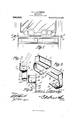
- Figure 1 is a front elevation of a sideboard fitted with my device.
- Fig. 2 is a vertical section showing the inner or folding section.
- Fig. 3 is a detailed perspective, of the outer and inner sections.
- ig. 4 is a vertical section of the device showing a modified form of bracket intended to secure the device to a wall.
- the batten or holder consists of two angular sections preferably formed of metal or other suitable material, and arranged to fold one within the other. Each section is provided at its outer end with a hook adapted to straddlc the top board of the article to which it is to be applied.
- a piece of suitable sheet metal of proper length, and width is bent at approximately its longitudinal center, and throughout its entire length so as to form a vertical front wall 1, and base 2.
- the latter' is adapted to rest upon the fiat surface of the top board to which it is to be applied, and adjacent the back board, while the edge of the plates or dishes to be supported are placed upon its upper face and held in a substantially vertical position by the front wall 2.
- a portion adjacent the edge of the front wall is bent inwardly and ⁇ downwardly throughout the entire length of the wall so as to form an upper guide 3, and the base 2 is similarly bent to form a lower guide ⁇ 4.
- a vertical wall 5 connects the end of the base 2 with the vertical wall 1.
- the smaller or inner section is formed of ⁇ metal or other suitable material, and is bent similar to the outer section so as to form a base 6, and vertical Wall 7 each of which is adjacent its outer edge bent upon itself throughout its entire length as shown at 8 and 9.
- the width of the front Wall 7 and base 8 will be slightly less than the width ofthe wall 1 and base 2, in order that they may conveniently enter the guides 3 and 4.
- a vertical end wall 10 connects one end of the front wall and base as shown in Fig. 3.
- Each section is provided at its outer end and directly beneath the end walls 5 and l0, with an engaging hook, which in the present instance is shown as being formed of a piece of resilient metal, one end of which is secured to the outer end of the base and then curved downwardly and inwardly, as shown at 11,
- each hook is provided at its upward y sprung portion 12 with a threaded opening into which 'fits a suitable thumb screw 13, the threaded terminal of which is adapted to be brought to bear on the lower face of the shelf or lthe like to which the device may be applied.
- a further feature of this construction is that it permits the device to be applied to china closets, wherein glass shelves are usually employed.
- Fig. 4 the device is shown in position to support dishes against the wall of a room, in this instance the hooks are replaced by right angular brackets.
- One of these members is disposed at the opposite outer ends of the device having one side 14 suitably secured to the outer face of the base 2, while the adjacent side 15 which is to bear against the wall is intermediately provided with lateral lugs 16, having openings for nails or screws 17 by means of which it is secured in place.
- a strut 18 connects the terminals of the adjacent sides and serves as an additional brace for the top side 14.
- a dish rack including extensible telescopic sections each formed of a single piece of metal bent to form angularly disposed members, one of which constitutes a base and the other a vertical iiange, the longitudinal edges of the base and flange of one section being bent inwardly and downwardly to form guide anges adapted to receive corresponding guide iianges formed on the longitudinal edges of the base and vertical flange of the'mating section, each section having its base formed with a flat unobstructed surface extending the entire width and length of the same, spring clamping arms of the same width as said sections secured to the outer ends thereof and having their inner ends extended beneath the adjacent section and provided with threaded apertures, and clamping screws engaging the threaded walls of the apertures for retaining said sections in position on a support.
- a dish rack including extensible telescopic sections of angular formation and closed at the front and open at the rear, one of said sections having its opposite longitudinal edges bent inwardly and downwardly to form guide flanges adapted to receive corresponding guide iianges formed on the mating section, each section being provided with an integral up-standing end wall and having its base formed with a fiat unobstructed bearing surface extending the entire width and length of the section for engagement with a support, a spring clamping member carried by the outer end of each section and extending in the same longitudinal plane with each section and extended beneath the bottom of the Same, and a clamping screw threaded in the free end of each clamping member and adapted to bear against the support for retaining the rack in position thereon.
Description
N'. L. LlLLIBRIDGE.
DISH BATTEN. @PPLIUAT'ION FILED snrT.4,19o.
906,809. Patented Dec. 15, 1908,
NETTIE L. LILLIBRIDGE, OF .IAMESTOWN, NEW YORK.
DISH-BATTEN.
,Specification of Letters Patent.
Patented Dec. 15, 1908.
Application filed September 4, 1908. Serial No. 452,141.
To all whom it may concern:
Be it known that I, NETTIE L. LILLIBRIDGE, a citizen of the United States, residing at Jamestown, in the county of Chautauqua and State of New York, have invented a new and useful Dish-Batte1i, of which the following is a specification. n
This invention relates to dish holders, such as are used for supporting dishes in a vertical i 3 rative and display purposes.
It is well known that the usual method of fitting a sideboard or buffet to hold dishes in a vertical position, consists in securing a batten adjacent the backboard. This arrangement has many disadvantages chief among which is, the batten becomes a permanent part of the sideboard or buffet, and in many cases where it is not desired to have the dishes stand on their edges the presence of r the batten destroys the level surface of the top board. The present invention aims to remedy this defect b y employing a batteri which can be removably attached to any article of furniture used to display dishes.
Another object is to provide a device which can be readily adjusted to fit the various sizes of suoli articles.
A further object is to provide a construction wherein the device may be secured to a wall or the top of wainscoting to support dishes.
IVith these and other objects in view as will more fully hereinafter appear, the present invention consists in certain novel features of construction and arrangement of parts, hereinafter fully described, illustrated in the accompanying drawings, and more particularly pointed out in the appended claims, it being understood that various changes in the form, proportion, size and minor details of the device may be made Without departing from the spirit or sacrificing any of the advantages of t e invention.
In the accom anying drawings forming part of this speciipication: Figure 1 is a front elevation of a sideboard fitted with my device. Fig. 2 is a vertical section showing the inner or folding section. Fig. 3 is a detailed perspective, of the outer and inner sections.
ig. 4 is a vertical section of the device showing a modified form of bracket intended to secure the device to a wall.
Similar numerals of reference are employedv to designate corresponding parts throughout.
The batten or holder consists of two angular sections preferably formed of metal or other suitable material, and arranged to fold one within the other. Each section is provided at its outer end with a hook adapted to straddlc the top board of the article to which it is to be applied.
In forming the larger section, a piece of suitable sheet metal of proper length, and width is bent at approximately its longitudinal center, and throughout its entire length so as to form a vertical front wall 1, and base 2. The latter' is adapted to rest upon the fiat surface of the top board to which it is to be applied, and adjacent the back board, while the edge of the plates or dishes to be supported are placed upon its upper face and held in a substantially vertical position by the front wall 2.
By referring now to Figs. 1 and 2, it will be observed that a portion adjacent the edge of the front wall is bent inwardly and` downwardly throughout the entire length of the wall so as to form an upper guide 3, and the base 2 is similarly bent to form a lower guide` 4. A vertical wall 5 connects the end of the base 2 with the vertical wall 1.
The smaller or inner section is formed of` metal or other suitable material, and is bent similar to the outer section so as to form a base 6, and vertical Wall 7 each of which is adjacent its outer edge bent upon itself throughout its entire length as shown at 8 and 9. By this construction the width of the front Wall 7 and base 8, will be slightly less than the width ofthe wall 1 and base 2, in order that they may conveniently enter the guides 3 and 4.
A vertical end wall 10, connects one end of the front wall and base as shown in Fig. 3. Thus it Will be seen that I have provided a batteri which can be applied and adjusted to fit most forms of sideboards and buffets now in use.
Each section is provided at its outer end and directly beneath the end walls 5 and l0, with an engaging hook, which in the present instance is shown as being formed of a piece of resilient metal, one end of which is secured to the outer end of the base and then curved downwardly and inwardly, as shown at 11,
and adjacent the terminal is sprung slightly upward as shown at 12. It is designed that the distance between this sprung portion and the lower face of the base will be slightly less than the thickness of the top board to which it is to be applied, in order that the foot may bind sufficiently against the lower face of the top board to guard against outward movement caused by the pressure of the dishes against the front walls. In order to further guard against outward movement caused by excessive ressure each hook is provided at its upward y sprung portion 12 with a threaded opening into which 'fits a suitable thumb screw 13, the threaded terminal of which is adapted to be brought to bear on the lower face of the shelf or lthe like to which the device may be applied. A further feature of this construction is that it permits the device to be applied to china closets, wherein glass shelves are usually employed.
In the modification illustrated in Fig. 4 the device is shown in position to support dishes against the wall of a room, in this instance the hooks are replaced by right angular brackets. One of these members is disposed at the opposite outer ends of the device having one side 14 suitably secured to the outer face of the base 2, while the adjacent side 15 which is to bear against the wall is intermediately provided with lateral lugs 16, having openings for nails or screws 17 by means of which it is secured in place. A strut 18 connects the terminals of the adjacent sides and serves as an additional brace for the top side 14. Thus it will be seen that I have provided a device which is simple in structure, and comparatively inexpensive to manufacture, the utility of which will be readily appreciated.
Having thus described the invention what is claimed is 1. A dish rack including extensible telescopic sections each formed of a single piece of metal bent to form angularly disposed members, one of which constitutes a base and the other a vertical iiange, the longitudinal edges of the base and flange of one section being bent inwardly and downwardly to form guide anges adapted to receive corresponding guide iianges formed on the longitudinal edges of the base and vertical flange of the'mating section, each section having its base formed with a flat unobstructed surface extending the entire width and length of the same, spring clamping arms of the same width as said sections secured to the outer ends thereof and having their inner ends extended beneath the adjacent section and provided with threaded apertures, and clamping screws engaging the threaded walls of the apertures for retaining said sections in position on a support.
2. A dish rack including extensible telescopic sections of angular formation and closed at the front and open at the rear, one of said sections having its opposite longitudinal edges bent inwardly and downwardly to form guide flanges adapted to receive corresponding guide iianges formed on the mating section, each section being provided with an integral up-standing end wall and having its base formed with a fiat unobstructed bearing surface extending the entire width and length of the section for engagement with a support, a spring clamping member carried by the outer end of each section and extending in the same longitudinal plane with each section and extended beneath the bottom of the Same, and a clamping screw threaded in the free end of each clamping member and adapted to bear against the support for retaining the rack in position thereon.
In testimony that I claim the foregoing as my own, 1 have hereto affixed my signature in the presence of two witnesses.
NETTIE L. LILLIBRIDGE.
Witnesses:
GLENNA A. COBB, HARRIET A. SLACK.
Priority Applications (1)
| Application Number | Priority Date | Filing Date | Title |
|---|---|---|---|
| US45214108A US906809A (en) | 1908-09-04 | 1908-09-04 | Dish-batten. |
Applications Claiming Priority (1)
| Application Number | Priority Date | Filing Date | Title |
|---|---|---|---|
| US45214108A US906809A (en) | 1908-09-04 | 1908-09-04 | Dish-batten. |
Publications (1)
| Publication Number | Publication Date |
|---|---|
| US906809A true US906809A (en) | 1908-12-15 |
Family
ID=2975245
Family Applications (1)
| Application Number | Title | Priority Date | Filing Date |
|---|---|---|---|
| US45214108A Expired - Lifetime US906809A (en) | 1908-09-04 | 1908-09-04 | Dish-batten. |
Country Status (1)
| Country | Link |
|---|---|
| US (1) | US906809A (en) |
Cited By (4)
| Publication number | Priority date | Publication date | Assignee | Title |
|---|---|---|---|---|
| US2568046A (en) * | 1949-09-15 | 1951-09-18 | Wilkinson Gresh Inc | Shelf for vehicle bodies |
| US3186559A (en) * | 1963-06-07 | 1965-06-01 | Glowa Henry | Shelf support rack |
| US6092676A (en) * | 1999-05-10 | 2000-07-25 | Graham; Norman G. | Plate rail |
| US6405878B1 (en) | 2001-01-23 | 2002-06-18 | Norman G. Graham | Plate rail with easily removed arm |
-
1908
- 1908-09-04 US US45214108A patent/US906809A/en not_active Expired - Lifetime
Cited By (4)
| Publication number | Priority date | Publication date | Assignee | Title |
|---|---|---|---|---|
| US2568046A (en) * | 1949-09-15 | 1951-09-18 | Wilkinson Gresh Inc | Shelf for vehicle bodies |
| US3186559A (en) * | 1963-06-07 | 1965-06-01 | Glowa Henry | Shelf support rack |
| US6092676A (en) * | 1999-05-10 | 2000-07-25 | Graham; Norman G. | Plate rail |
| US6405878B1 (en) | 2001-01-23 | 2002-06-18 | Norman G. Graham | Plate rail with easily removed arm |
Similar Documents
| Publication | Publication Date | Title |
|---|---|---|
| US6378709B1 (en) | Single standard shelving system | |
| US5379976A (en) | Wall mounting system | |
| US3233852A (en) | Supporting shelf assembly | |
| US2937758A (en) | Holder for clothing and like | |
| US946337A (en) | Display-shelving. | |
| US906809A (en) | Dish-batten. | |
| US2118525A (en) | Knock-down desk | |
| US1090724A (en) | Combined shelf and towel-rack. | |
| JP2014050516A (en) | Furniture overturning prevention device | |
| US3417875A (en) | Convenience rack storable as a decorative hanging | |
| US773972A (en) | Adjustable support. | |
| US1807517A (en) | Attachable bracket shelf | |
| US1518148A (en) | Display rack | |
| US837221A (en) | Table. | |
| US918045A (en) | Easel. | |
| KR102241930B1 (en) | Multipurpose supporter | |
| US2633996A (en) | Auxiliary shelf | |
| US2694543A (en) | Mirror support device | |
| US5769246A (en) | Holder for mixer attachments | |
| US780052A (en) | Support for picture-frames, &c. | |
| US1244497A (en) | Folding screen. | |
| US1835037A (en) | Telephone directory holder | |
| JP4553347B2 (en) | Storage furniture | |
| KR102571310B1 (en) | A shelf for installing furniture | |
| US1080530A (en) | Display-rack. |