US9059655B2 - Method for fault recognition in an electric machine controlled by an inverter in a motor vehicle and device for monitoring an operation of the electric machine - Google Patents
Method for fault recognition in an electric machine controlled by an inverter in a motor vehicle and device for monitoring an operation of the electric machine Download PDFInfo
- Publication number
- US9059655B2 US9059655B2 US13/517,922 US201013517922A US9059655B2 US 9059655 B2 US9059655 B2 US 9059655B2 US 201013517922 A US201013517922 A US 201013517922A US 9059655 B2 US9059655 B2 US 9059655B2
- Authority
- US
- United States
- Prior art keywords
- inverter
- threshold value
- electric machine
- function
- lower threshold
- Prior art date
- Legal status (The legal status is an assumption and is not a legal conclusion. Google has not performed a legal analysis and makes no representation as to the accuracy of the status listed.)
- Active, expires
Links
Images


Classifications
-
- H—ELECTRICITY
- H02—GENERATION; CONVERSION OR DISTRIBUTION OF ELECTRIC POWER
- H02P—CONTROL OR REGULATION OF ELECTRIC MOTORS, ELECTRIC GENERATORS OR DYNAMO-ELECTRIC CONVERTERS; CONTROLLING TRANSFORMERS, REACTORS OR CHOKE COILS
- H02P29/00—Arrangements for regulating or controlling electric motors, appropriate for both AC and DC motors
- H02P29/02—Providing protection against overload without automatic interruption of supply
-
- B60L11/14—
-
- B—PERFORMING OPERATIONS; TRANSPORTING
- B60—VEHICLES IN GENERAL
- B60L—PROPULSION OF ELECTRICALLY-PROPELLED VEHICLES; SUPPLYING ELECTRIC POWER FOR AUXILIARY EQUIPMENT OF ELECTRICALLY-PROPELLED VEHICLES; ELECTRODYNAMIC BRAKE SYSTEMS FOR VEHICLES IN GENERAL; MAGNETIC SUSPENSION OR LEVITATION FOR VEHICLES; MONITORING OPERATING VARIABLES OF ELECTRICALLY-PROPELLED VEHICLES; ELECTRIC SAFETY DEVICES FOR ELECTRICALLY-PROPELLED VEHICLES
- B60L3/00—Electric devices on electrically-propelled vehicles for safety purposes; Monitoring operating variables, e.g. speed, deceleration or energy consumption
- B60L3/0023—Detecting, eliminating, remedying or compensating for drive train abnormalities, e.g. failures within the drive train
- B60L3/0061—Detecting, eliminating, remedying or compensating for drive train abnormalities, e.g. failures within the drive train relating to electrical machines
-
- B—PERFORMING OPERATIONS; TRANSPORTING
- B60—VEHICLES IN GENERAL
- B60L—PROPULSION OF ELECTRICALLY-PROPELLED VEHICLES; SUPPLYING ELECTRIC POWER FOR AUXILIARY EQUIPMENT OF ELECTRICALLY-PROPELLED VEHICLES; ELECTRODYNAMIC BRAKE SYSTEMS FOR VEHICLES IN GENERAL; MAGNETIC SUSPENSION OR LEVITATION FOR VEHICLES; MONITORING OPERATING VARIABLES OF ELECTRICALLY-PROPELLED VEHICLES; ELECTRIC SAFETY DEVICES FOR ELECTRICALLY-PROPELLED VEHICLES
- B60L50/00—Electric propulsion with power supplied within the vehicle
- B60L50/10—Electric propulsion with power supplied within the vehicle using propulsion power supplied by engine-driven generators, e.g. generators driven by combustion engines
- B60L50/16—Electric propulsion with power supplied within the vehicle using propulsion power supplied by engine-driven generators, e.g. generators driven by combustion engines with provision for separate direct mechanical propulsion
-
- B—PERFORMING OPERATIONS; TRANSPORTING
- B60—VEHICLES IN GENERAL
- B60L—PROPULSION OF ELECTRICALLY-PROPELLED VEHICLES; SUPPLYING ELECTRIC POWER FOR AUXILIARY EQUIPMENT OF ELECTRICALLY-PROPELLED VEHICLES; ELECTRODYNAMIC BRAKE SYSTEMS FOR VEHICLES IN GENERAL; MAGNETIC SUSPENSION OR LEVITATION FOR VEHICLES; MONITORING OPERATING VARIABLES OF ELECTRICALLY-PROPELLED VEHICLES; ELECTRIC SAFETY DEVICES FOR ELECTRICALLY-PROPELLED VEHICLES
- B60L2240/00—Control parameters of input or output; Target parameters
- B60L2240/10—Vehicle control parameters
- B60L2240/36—Temperature of vehicle components or parts
-
- B—PERFORMING OPERATIONS; TRANSPORTING
- B60—VEHICLES IN GENERAL
- B60L—PROPULSION OF ELECTRICALLY-PROPELLED VEHICLES; SUPPLYING ELECTRIC POWER FOR AUXILIARY EQUIPMENT OF ELECTRICALLY-PROPELLED VEHICLES; ELECTRODYNAMIC BRAKE SYSTEMS FOR VEHICLES IN GENERAL; MAGNETIC SUSPENSION OR LEVITATION FOR VEHICLES; MONITORING OPERATING VARIABLES OF ELECTRICALLY-PROPELLED VEHICLES; ELECTRIC SAFETY DEVICES FOR ELECTRICALLY-PROPELLED VEHICLES
- B60L2240/00—Control parameters of input or output; Target parameters
- B60L2240/40—Drive Train control parameters
- B60L2240/42—Drive Train control parameters related to electric machines
- B60L2240/423—Torque
-
- H—ELECTRICITY
- H02—GENERATION; CONVERSION OR DISTRIBUTION OF ELECTRIC POWER
- H02M—APPARATUS FOR CONVERSION BETWEEN AC AND AC, BETWEEN AC AND DC, OR BETWEEN DC AND DC, AND FOR USE WITH MAINS OR SIMILAR POWER SUPPLY SYSTEMS; CONVERSION OF DC OR AC INPUT POWER INTO SURGE OUTPUT POWER; CONTROL OR REGULATION THEREOF
- H02M1/00—Details of apparatus for conversion
- H02M1/32—Means for protecting converters other than automatic disconnection
-
- Y—GENERAL TAGGING OF NEW TECHNOLOGICAL DEVELOPMENTS; GENERAL TAGGING OF CROSS-SECTIONAL TECHNOLOGIES SPANNING OVER SEVERAL SECTIONS OF THE IPC; TECHNICAL SUBJECTS COVERED BY FORMER USPC CROSS-REFERENCE ART COLLECTIONS [XRACs] AND DIGESTS
- Y02—TECHNOLOGIES OR APPLICATIONS FOR MITIGATION OR ADAPTATION AGAINST CLIMATE CHANGE
- Y02T—CLIMATE CHANGE MITIGATION TECHNOLOGIES RELATED TO TRANSPORTATION
- Y02T10/00—Road transport of goods or passengers
- Y02T10/60—Other road transportation technologies with climate change mitigation effect
- Y02T10/64—Electric machine technologies in electromobility
-
- Y02T10/642—
-
- Y—GENERAL TAGGING OF NEW TECHNOLOGICAL DEVELOPMENTS; GENERAL TAGGING OF CROSS-SECTIONAL TECHNOLOGIES SPANNING OVER SEVERAL SECTIONS OF THE IPC; TECHNICAL SUBJECTS COVERED BY FORMER USPC CROSS-REFERENCE ART COLLECTIONS [XRACs] AND DIGESTS
- Y02—TECHNOLOGIES OR APPLICATIONS FOR MITIGATION OR ADAPTATION AGAINST CLIMATE CHANGE
- Y02T—CLIMATE CHANGE MITIGATION TECHNOLOGIES RELATED TO TRANSPORTATION
- Y02T10/00—Road transport of goods or passengers
- Y02T10/60—Other road transportation technologies with climate change mitigation effect
- Y02T10/70—Energy storage systems for electromobility, e.g. batteries
-
- Y—GENERAL TAGGING OF NEW TECHNOLOGICAL DEVELOPMENTS; GENERAL TAGGING OF CROSS-SECTIONAL TECHNOLOGIES SPANNING OVER SEVERAL SECTIONS OF THE IPC; TECHNICAL SUBJECTS COVERED BY FORMER USPC CROSS-REFERENCE ART COLLECTIONS [XRACs] AND DIGESTS
- Y02—TECHNOLOGIES OR APPLICATIONS FOR MITIGATION OR ADAPTATION AGAINST CLIMATE CHANGE
- Y02T—CLIMATE CHANGE MITIGATION TECHNOLOGIES RELATED TO TRANSPORTATION
- Y02T10/00—Road transport of goods or passengers
- Y02T10/60—Other road transportation technologies with climate change mitigation effect
- Y02T10/7072—Electromobility specific charging systems or methods for batteries, ultracapacitors, supercapacitors or double-layer capacitors
-
- Y02T10/7077—
Definitions
- the present invention relates to a method for fault recognition in an electric machine controlled by an inverter in a motor vehicle and a device for monitoring an operation of an electric machine controlled by an inverter in a motor vehicle.
- Electric machines are used, for example, in hybrid vehicles, where they are operated either in the motor mode or in the generator mode.
- the electric machine In the motor mode, the electric machine generates an additional drive torque, which supports an internal combustion engine, for example, in an acceleration phase; in the generator mode, it generates electrical energy, which is stored in an energy storage device such as a battery or a super-cab.
- the operating mode and power of the electric machine are set with the aid of an inverter.
- the pulse-controlled inverter When a malfunction, for example, a phase overcurrent, is recognized, the pulse-controlled inverter is switched into a safe state in order to prevent possible damage to the electrical components.
- a malfunction for example, a phase overcurrent
- the pulse-controlled inverter is switched into a safe state in order to prevent possible damage to the electrical components.
- two different switch-off methods are known from the related art. In a first method, all switches connected to a low potential (low-side switches) of the pulse-controlled inverter are closed and all switches connected to a high potential (high-side switches) of the pulse-controlled inverter are open. This operating mode is also referred to as short-circuit mode. In another switch-off method, all switches of the pulse-controlled inverter are open. This is also referred to as isolation mode.
- a method is discussed in DE 10 2006 003 254 A1 for switching off an electric machine using pulse-controlled inverters in the event of a fault provides for minimizing undesirable side effects when switching off the electric machine and maximizing the regular machine operation by switching the electric machine first into an isolation mode, in which all switches of the pulse-controlled inverter are open, and subsequently into a short-circuit mode, in which the switches connected to the high potential are open and the switches connected to the low potential are closed.
- a method for handling a fault in electric machines of a hybrid drive is discussed in DE 10 2007 020 509 A1 in which it is initially detected whether at least one operating parameter of the electric machine is greater than an associated operating parameter limiting value. If it is detected that at least one operating parameter is greater than the associated limiting value, a supply connection of the electric machine is activated for a time interval associated with the operating parameter and the supply connection is short-circuited to ground after the elapse of the time interval.
- the method according to the present invention for fault detection in an electric machine controlled by an inverter in a motor vehicle provides that the phase currents of the electric machine are ascertained and a fault is recognized if at least one of the phase currents or a variable derived therefrom exceeds a predefined upper threshold value.
- the upper threshold value is established as a function of operating parameters of the motor vehicle, in particular of the electric machine and/or of the inverter. All phase currents of the electric machine are advantageously ascertained by measuring. Alternatively, however, the phase currents may also be partially ascertained by calculation.
- the inverter in particular the power components of the inverter, often also referred to as power semiconductors, to better protect itself.
- the operating limits of the inverter defined by the power components of the inverter may be extended according to the situation.
- the exemplary embodiments and/or exemplary methods of the present invention allow the maximally occurring phase current to be limited as a function of the operating point. Since the phase current directly affects the torque-forming variables of the electric machine, the operating reliability of the motor vehicle may also be increased in this way.
- a fault is diagnosed also if at least one of the variables derived from the phase currents is less than a predefined lower threshold value.
- the lower threshold value is established as a function of operating parameters of the motor vehicle, in particular of the electric machine and/or of the inverter.
- Phase currents I U , I V , and I W may be mapped, for example, to the corresponding voltage values in a voltage interval of 0 V to 5 V.
- the voltage threshold value may be established, for example, in such a way that it is exactly in the middle of the voltage interval, i.e., at 2.5 V.
- a lower threshold value in addition to an upper threshold value for a positive half-wave of the phase current, a lower threshold value, having a different absolute value, also results for a negative half-wave of the phase current.
- Another specific embodiment of the present invention provides that the upper and/or the lower threshold value(s) is/are selected from a set of stored threshold values.
- the storage of multiple predefined threshold values and the selection of an instantaneously valid threshold value as a function of the operating point may be implemented in a particularly simple manner and using little hardware or software complexity.
- the upper and/or the lower threshold value(s) is/are established as a function of an operating state of the electric machine.
- Voltage U lh applied to a power switching element in an inverter results from the sum of an instantaneous intermediate circuit voltage U zk and switching overvoltage U schalt .
- voltage U lh applied to the power switching element must always be smaller than a maximum voltage U max .
- voltage U lh applied to the power switching element is essentially determined by intermediate circuit voltage U zk and phase current I phase . Due to the internal resistance of the high-voltage battery and its leads, however, a significantly higher intermediate circuit voltage is applied to the power switching elements of the inverter in generator mode of the electric machine than in the motor mode. Consequently, in the motor mode a significantly higher phase current may be allowed than in the generator mode of the electric machine. In order to make the best possible use of the operating range of the inverter, it is therefore expedient to establish the upper and/or the lower threshold value(s) as a function of the operating state of the electric machine, i.e., at least to provide different threshold values for the generator and the motor modes.
- one specific embodiment of the present invention provides that the upper and/or the lower threshold value(s) be established as a function of intermediate circuit voltage U zk .
- the upper threshold value decreases with increasing intermediate circuit voltage U zk
- the lower threshold value may increase. Accordingly, in the event of decreasing intermediate circuit voltage U zk , the upper threshold value increases, while the lower threshold value may decrease.
- the upper and/or the lower threshold value(s) is/are established as a function of a temperature, in particular the junction temperature, of a power component subject to electrical breakthrough, in particular of a power switching element, of the inverter.
- the blocking voltages of the components depend on the temperature of the particular component, it is advantageous to establish the allowable phase current as a function of the temperature at these components.
- the upper threshold value decreases with increasing component temperature, while the lower threshold value may increase. Accordingly, the upper threshold value increases with decreasing component temperature, while the lower threshold value may decrease.
- the junction temperature of the power switching elements is of special significance.
- the upper and/or the lower threshold value(s) is/are established as a function of the intensity of the phase currents and/or as a function of the flow times of the phase currents.
- both the intensity of the phase currents and their flow times i.e., the time period during which a phase current flows, affect the power loss across the power switching elements of the inverter.
- the upper threshold value decreases with increasing current intensity and/or increasing flow time, while the lower threshold value may increase. Accordingly, the upper threshold value increases with decreasing current intensity and/or decreasing flow time, while the lower threshold value may decrease.
- the upper and/or the lower threshold value(s) may also be established as a function of a collector-emitter voltage or a source-drain voltage of a power switching element of the inverter, as a function of a temperature of a heat sink of a power component of the inverter, in particular of a power switching element, or also as a function of a collector current or a source current of a power switching element of the inverter. All these variables affect the thermal conditions at the power components, which are subject to breakthrough, of the inverter and therefore affect the phase currents still allowable under the particular conditions. The intrinsic reliability of the inverter may thus be increased, while the maximally possible phase currents are utilized as a function of the operating point by taking into account these operating parameters.
- the exemplary embodiments and/or exemplary methods of the present invention provide a device for monitoring an operation of an electric machine controlled by an inverter in a motor vehicle, having a phase current monitoring device for comparing phase currents or variables derived therefrom of the electric machine to a predefined upper threshold value, and a control unit for establishing the upper threshold value as a function of operating parameters of the motor vehicle, in particular of the electric machine and/or of the inverter.
- the control unit may be implemented as a standalone unit, for example in the form of a microcontroller, or in the form of a hardware circuit.
- the phase current monitoring device may also compare a variable derived from the phase currents to a lower threshold value, and the control unit may establish the lower threshold value as a function of operating parameters of the motor vehicle, in particular of the electric machine and/or of the inverter.
- the device according to the present invention is basically configured in such a way that it is capable of carrying out the method according to the present invention, including all specific embodiments.
- FIG. 1 shows a schematic illustration of a three-phase electric machine controlled by an inverter.
- FIG. 2 shows a schematic illustration of the voltage components on a power switching element of an inverter.
- FIG. 3 shows a schematic block diagram of a device according to the present invention for monitoring an operation of an electric machine controlled by an inverter.
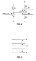
- FIG. 4 shows a schematic illustration of a circuit configuration in a phase current monitoring device for establishing a lower and an upper voltage threshold value according to one specific embodiment of the present invention.
- FIG. 5 shows a schematic illustration of the voltage threshold values established with the aid of a circuit configuration according to FIG. 4 .
- FIG. 1 shows a schematic illustration of an electric machine 1 having an inverter connected thereto in the form of a pulse-controlled inverter 2 .
- Pulse-controlled inverter 2 includes multiple power components—often referred to as power semiconductors—in the form of power switching elements 3 a through 3 f , which are connected to individual phases U, V, W of electric machine 1 and connect phases U, V, W either to a high supply potential (battery voltage U Bat+ ) or a low supply potential (U Bat ⁇ ).
- Pulse-controlled inverter 2 also further includes power components in the form of freewheeling diodes 4 a through 4 f , which in the illustrated exemplary embodiment are situated in the form of a six-pulse rectifier bridge circuit. Each diode 4 a through 4 f is connected in parallel to one of power switching elements 3 a through 3 f .
- the power switching elements may, for example, be designed as IGBTs (Insulated Gate Bipolar Transistors) or as MOSFETs (Metal Oxide Semiconductor Field-effect Transistors).
- Pulse-controlled inverter 2 determines the power and the mode of operation of electric machine 1 and is controlled accordingly by a control unit 6 .
- Electric machine 1 may thus be operated either in the motor mode or in the generator mode. In the motor mode, it generates an additional drive torque, which supports the internal combustion engine, for example, in an acceleration phase.
- the generator mode mechanical energy is converted into electrical energy and stored in an energy storage device, here in a battery 5 .
- Battery 5 is connected to a power supply system (not illustrated) in a motor vehicle; the battery may be designed as a high-voltage battery, and the power supply system may be designed as a high-voltage traction system in a hybrid vehicle, for example.
- a so-called intermediate circuit capacitor C which is essentially used for stabilizing battery voltage U Bat and to which an intermediate circuit voltage U zk is applied, is situated in parallel to pulse-controlled inverter 2 .
- Phase currents I U , I V , and I W in phases I, U, and W of electric machine 1 are ascertained with the help of current sensors (cf., FIG. 4 ). All phase currents I U , I V , and I W are advantageously ascertained by measuring. However, as an alternative, it is also possible to measure only part of the phase currents via current sensors and to ascertain the remaining phase currents mathematically.
- phase currents I U , I V , and I W are necessary to monitor phase currents I U , I V , and I W and to transfer pulse-controlled inverter 2 to a safe operating state if at least one of phase currents I U , I V , or I W exceeds a predefined threshold value, often also referred to as overcurrent threshold. If a malfunction is recognized in the form of an excessively high current in at least one of phases U, V, or W, pulse-controlled inverter 2 , triggered by control unit 6 , automatically switches into an isolation mode or short-circuit mode.
- a voltage U lh across a power switching element 3 results as a sum of an intermediate circuit voltage U zk across intermediate circuit capacitor C and a switching overvoltage U schalt (see FIG. 2 ).
- voltage U lh applied to the power switching element must always be smaller than a maximum voltage U. Switching overvoltage U schalt directly depends on the particular phase current.
- phase currents I U , I V , and I W are compared to one single fixedly predefined overcurrent value, the latter must be established with reference to the highest possible intermediate circuit voltage U zk and the resulting maximally allowable switching overvoltage U schalt .
- a response to a decrease in intermediate circuit voltage U zk is no longer possible, so that the operating range of pulse-controlled inverter 2 in operating situations of this type is not optimally utilized.
- an upper threshold value for phase currents I U , I V , and I W is established as a function of operating parameters of the motor vehicle, in particular of electric machine 1 and/or of pulse-controlled inverter 2 .
- the maximally allowable phase current i.e., the maximally possible phase current not resulting in the destruction of power switching elements 3 and thus to significantly extend the operating range of pulse-controlled inverter 2 .
- FIG. 3 shows a schematic block diagram of a device according to the present invention for monitoring an operation of an electric machine controlled by an inverter.
- a phase current monitoring device 31 is connected between control unit 6 , which controls pulse-controlled inverter 2 , and current sensors 30 a through 30 c , which detect phase currents I U , I V , and I W .
- Phase currents I U , I V , and I W are compared to a predefined upper threshold value by phase current monitoring device 31 , for example, with the aid of comparators. If at least one of phase currents I U , I V , or I W exceeds the upper threshold value, a fault is recognized and reported to control unit 6 and to a fault logic 32 in the form of a signal NIPHMAX.
- the fault logic is illustrated in FIG. 3 as a standalone unit, but it may also be integrated into control unit 6 .
- Fault logic 32 and/or control unit 6 then transfer(s) pulse-controlled inverter 2 into a safe operating state in the form of a freewheel or a short-circuit.
- control unit 6 transmits to phase current monitoring device 31 a control signal IPHMAX-CTRL, with the help of which the upper threshold value is established.
- Multiple upper threshold values are advantageously stored in phase current monitoring device 31 , from which an instantaneously valid threshold value is selected as a function of control signal IPHMAX-CTRL. In this way, the upper threshold value may be established as a function of the operating point.
- control signal IPHMAX-CTRL may be implemented, for example, in the form of a simple logic signal, which may assume the “high” or the “low” levels.
- the transmission of a low level results in setting a first upper threshold value for the motor mode, and the transmission of a high level results in setting a second upper threshold value for the generator mode.
- multiple control signals IPHMAX-CTRL of this type may be provided.
- the control signal may, however, also be implemented in the form of a pulse-width modulated signal or of an analog signal.
- phase currents I U , I V , and I W may be initially converted into an appropriate other variable, such as a voltage, and then to compare the corresponding voltages to a voltage threshold value.
- Phase currents I V , I V , and I W may be mapped, for example, to the corresponding voltage values in a voltage interval of 0 V to 5 V.
- the voltage threshold value may be established, for example, in such a way that it is exactly in the middle of the voltage interval, i.e., at 2.5 V.
- a lower threshold value in addition to an upper threshold value for a positive half-wave of the phase current, a lower threshold value, having a different absolute value, also results for a negative half-wave of the phase current.
- this lower threshold value is also established as a function of the operating point.
- FIG. 4 shows a schematic illustration of a circuit configuration in a phase current monitoring device 31 for establishing a lower and an upper voltage threshold value according to one specific embodiment of the present invention.
- Control signal IPHMAX-CTRL is applied to a base terminal of a first transistor T 1 .
- a collector terminal of first transistor T 1 is connected via a pull-up resistor R 1 to a gate terminal of a second transistor T 2 , designed in the illustrated specific embodiment as a field-effect transistor T 2 .
- a voltage divider which is formed by a series connection of three resistors R 1 , R 2 , and R 3 [R 1 , R 2 , and R 3 according to the figure], is connected downstream from second transistor T 2 .
- a drain terminal of second transistor T 2 is connected to a first center tap M 1 between first resistor R 1 and second resistor R 2 [R 1 and R 2 according to the figure] of the voltage divider, and a source terminal of second transistor T 2 is connected to a second center tap M 2 between second resistor R 2 and third resistor R 3 [R 2 and R 3 according to the figure].
- the upper threshold value for a voltage corresponding to the phase current is collected at first central tap M 1 .
- the lower threshold value for a voltage corresponding to the phase current is collected at second center tap M 2 .
- control signal IPHMAX-CTRL assumes a value of 0 V (low level) in the case of a motor mode of electric machine 1 .
- second transistor T 2 is switched on via first transistor T 1 and pull-up resistor R 1 .
- a voltage ratio of 1:1 is thus established across the voltage divider, so that the upper and the lower threshold values for the positive and the negative half-waves of the phase current coincide in a value of 2.5 V, for example.
- control signal IPHMAX-CTRL has a high level, second transistor T 2 is closed, so that different voltage values result for the upper and the lower threshold values. In the case of a positive half-wave, the upper threshold value must not be exceeded, and in the case of a negative half-wave, the voltage value must not drop below the lower threshold value.
- phase current monitoring device 31 which is suitable for setting the upper and the lower threshold values for the phase currents if phase currents I U , I V , and I W are converted into the corresponding voltages prior to the comparison to the threshold values.
- FIG. 5 shows a schematic illustration of the voltage threshold values established with the aid of a circuit configuration according to FIG. 4 .
- the upper threshold value for the motor mode which in the selected specific embodiment coincides with the lower threshold value for the motor mode, is labeled using reference numeral 50 .
- the upper and the lower threshold values for the generator mode are illustrated as dashed lines 51 and 52 , respectively.
- Threshold values 51 and 52 are symmetrical with respect to mean value 2.5 V and characterize a phase current of +m amperes for a positive half-wave and ⁇ m amperes for a negative half-wave of the phase current.
- phase currents I U , I V , and I W include the junction temperatures of power switching elements 3 a through 3 f , the intensities and the flow times of phase currents I U , I V , and I W , the collector-emitter voltages or source-drain voltages of power switching elements 3 a through 3 f , the temperatures at the heat sinks of power switching elements 3 a through 3 f , or also collector currents or source currents of power switching elements 3 a through 3 f , the power losses and/or the thermal conditions at power switching elements 3 a through 3 f , and thus the maximally allowable phase currents I U , I V , and I W .
- exemplary embodiments and/or exemplary methods of the present invention are described with reference to a three-phase electric machine, but, of course, it is also applicable to electric machines having more or fewer than three phases.
Landscapes
- Engineering & Computer Science (AREA)
- Power Engineering (AREA)
- Transportation (AREA)
- Mechanical Engineering (AREA)
- Life Sciences & Earth Sciences (AREA)
- Sustainable Development (AREA)
- Sustainable Energy (AREA)
- Inverter Devices (AREA)
- Control Of Ac Motors In General (AREA)
- Electric Propulsion And Braking For Vehicles (AREA)
Applications Claiming Priority (4)
| Application Number | Priority Date | Filing Date | Title |
|---|---|---|---|
| DE102009055055A DE102009055055A1 (de) | 2009-12-21 | 2009-12-21 | Verfahren zur Fehlererkennung bei einer durch einen Wechselrichter angesteuerten elektrischen Maschine in einem Kraftfahrzeug und Vorrichtung zur Überwachung eines Betriebs der elektrischen Maschine |
| DE102009055055.0 | 2009-12-21 | ||
| DE102009055055 | 2009-12-21 | ||
| PCT/EP2010/066785 WO2011085837A2 (fr) | 2009-12-21 | 2010-11-04 | Procédé de détection d'un défaut de fonctionnement d'une machine électrique alimentée par un onduleur à bord d'un véhicule automobile, ainsi que dispositif de surveillance du fonctionnement d'une machine électrique |
Publications (2)
| Publication Number | Publication Date |
|---|---|
| US20130041554A1 US20130041554A1 (en) | 2013-02-14 |
| US9059655B2 true US9059655B2 (en) | 2015-06-16 |
Family
ID=44304711
Family Applications (1)
| Application Number | Title | Priority Date | Filing Date |
|---|---|---|---|
| US13/517,922 Active 2031-10-27 US9059655B2 (en) | 2009-12-21 | 2010-11-04 | Method for fault recognition in an electric machine controlled by an inverter in a motor vehicle and device for monitoring an operation of the electric machine |
Country Status (5)
| Country | Link |
|---|---|
| US (1) | US9059655B2 (fr) |
| EP (1) | EP2516198B1 (fr) |
| CN (1) | CN102712255B (fr) |
| DE (1) | DE102009055055A1 (fr) |
| WO (1) | WO2011085837A2 (fr) |
Cited By (1)
| Publication number | Priority date | Publication date | Assignee | Title |
|---|---|---|---|---|
| US20140122944A1 (en) * | 2011-07-07 | 2014-05-01 | Bayersiche Motoren Werke Aktiengesellschaft | Documentation of Faults in a Fault Memory of a Motor Vehicle |
Families Citing this family (17)
| Publication number | Priority date | Publication date | Assignee | Title |
|---|---|---|---|---|
| DE102011006516A1 (de) * | 2011-03-31 | 2012-10-04 | Robert Bosch Gmbh | Verfahren zum Betreiben einer elektrischen Maschine in einem Kurzschlussbetrieb |
| JP6229248B2 (ja) * | 2011-06-03 | 2017-11-15 | 株式会社Gsユアサ | 蓄電モジュールのセル監視装置、および断線検出方法 |
| DE102011086079A1 (de) * | 2011-11-10 | 2013-05-16 | Robert Bosch Gmbh | Verfahren und Vorrichtung zum Ansteuern einer elektrischen Maschine |
| CN103795034A (zh) * | 2012-10-30 | 2014-05-14 | 通用电气公司 | 过电流保护系统和方法 |
| DE102013213044A1 (de) * | 2013-07-04 | 2015-01-08 | Voith Patent Gmbh | Permanentmagneterregte Elektromaschine |
| DE102013213802A1 (de) | 2013-07-15 | 2015-01-15 | Robert Bosch Gmbh | Überspannungsschutz für aktive Gleichrichter bei Lastabwurf |
| WO2015014362A1 (fr) * | 2013-08-02 | 2015-02-05 | Schaeffler Technologies Gmbh & Co. Kg | Procédé de détermination d'une défaillance dans un moteur électrique à commutation électronique |
| JP6365502B2 (ja) * | 2015-10-21 | 2018-08-01 | トヨタ自動車株式会社 | ハイブリッド車両 |
| DE102016201923B4 (de) | 2016-02-09 | 2021-10-28 | Valeo Siemens Eautomotive Germany Gmbh | Robuste Strombegrenzung für einen elektrischen Antrieb |
| CN105807742A (zh) * | 2016-03-10 | 2016-07-27 | 京东方科技集团股份有限公司 | 生产设备监控方法及系统 |
| CN105656342B (zh) * | 2016-04-15 | 2019-09-20 | 阳光电源股份有限公司 | 调整过流保护阈值的方法及过流保护阈值调整电路 |
| DE102017207886A1 (de) * | 2016-06-03 | 2017-12-07 | Robert Bosch Engineering And Business Solutions Private Limited | Steuereinheit und Verfahren zum Ansteuern einer Wechselrichterschaltung für einen Permanentmagnet-Synchronmotor |
| DE102016223539A1 (de) | 2016-11-28 | 2018-05-30 | Robert Bosch Gmbh | Schutzvorrichtung für ein elektrisches Antriebssystem, elektrisches Antriebssystem und Verfahren zum Betrieb eines elektrischen Antriebssystems |
| JP6305605B1 (ja) | 2017-05-22 | 2018-04-04 | 三菱電機株式会社 | モータ制御装置 |
| ES2717341B2 (es) | 2017-12-20 | 2020-07-06 | Power Electronics Espana S L | Sistema y metodo de proteccion dinamico contra sobrecorriente para convertidores de potencia |
| DE102020205024A1 (de) | 2020-04-21 | 2021-10-21 | Robert Bosch Gesellschaft mit beschränkter Haftung | Schaltvorrichtung und Verfahren zur Ansteuerung eines Halbleiterschalters |
| CN113521450B (zh) * | 2021-07-14 | 2022-10-25 | 巨翊科技(上海)有限公司 | 一种自动检测空载电流并修正电流报警阈值的方法 |
Citations (10)
| Publication number | Priority date | Publication date | Assignee | Title |
|---|---|---|---|---|
| JPH11192926A (ja) | 1997-12-26 | 1999-07-21 | Nippon Seiko Kk | 車両用乗員拘束保護装置 |
| EP1050425A2 (fr) | 1999-05-07 | 2000-11-08 | Honda Giken Kogyo Kabushiki Kaisha | Système de détection de défaut pour une système de propulsion |
| US20050204761A1 (en) * | 2004-03-19 | 2005-09-22 | Nissan Motor Co., Ltd. | Temperature detection device, temperature detection method, and computer-readable computer program product containing temperature detection program |
| JP2006129567A (ja) | 2004-10-27 | 2006-05-18 | Daihatsu Motor Co Ltd | 故障検出処理方法及び故障検出処理装置 |
| US20070093369A1 (en) | 2005-10-21 | 2007-04-26 | Bocchicchio Vincent J | Resistance exercise method and system |
| US20070093359A1 (en) * | 2005-10-26 | 2007-04-26 | Mitsubishi Denki Kabushiki Kaisha | Vehicular power control apparatus |
| DE102006003254A1 (de) | 2006-01-24 | 2007-07-26 | Robert Bosch Gmbh | Verfahren zum Abschalten einer elektrischen Maschine im Falle einer Störung |
| EP1983640A2 (fr) | 2007-04-20 | 2008-10-22 | Hitachi Industrial Equipment Systems Co. Ltd. | Appareil de conversion d'alimentation et procédé d'évaluation de la durée de vie d'alimentation |
| DE102007020509A1 (de) | 2007-05-02 | 2008-11-06 | Robert Bosch Gmbh | Fehlerbehandlung bei einer elektrischen Maschine eines Hybridantriebes |
| US20090251831A1 (en) * | 2006-06-30 | 2009-10-08 | Toyota Jidosha Kabushiki Kaisha | Motor drive device |
-
2009
- 2009-12-21 DE DE102009055055A patent/DE102009055055A1/de not_active Withdrawn
-
2010
- 2010-11-04 US US13/517,922 patent/US9059655B2/en active Active
- 2010-11-04 CN CN201080058208.9A patent/CN102712255B/zh active Active
- 2010-11-04 EP EP10779495.0A patent/EP2516198B1/fr active Active
- 2010-11-04 WO PCT/EP2010/066785 patent/WO2011085837A2/fr active Application Filing
Patent Citations (16)
| Publication number | Priority date | Publication date | Assignee | Title |
|---|---|---|---|---|
| JPH11192926A (ja) | 1997-12-26 | 1999-07-21 | Nippon Seiko Kk | 車両用乗員拘束保護装置 |
| EP1050425A2 (fr) | 1999-05-07 | 2000-11-08 | Honda Giken Kogyo Kabushiki Kaisha | Système de détection de défaut pour une système de propulsion |
| US6359405B1 (en) * | 1999-05-07 | 2002-03-19 | Honda Giken Kogyo Kabushiki Kaisha | Failure detection system for a propulsion system |
| US7607827B2 (en) * | 2004-03-19 | 2009-10-27 | Nissan Motor Co., Ltd. | Temperature detection device, temperature detection method, and computer-readable computer program product containing temperature detection program |
| US20050204761A1 (en) * | 2004-03-19 | 2005-09-22 | Nissan Motor Co., Ltd. | Temperature detection device, temperature detection method, and computer-readable computer program product containing temperature detection program |
| JP2006129567A (ja) | 2004-10-27 | 2006-05-18 | Daihatsu Motor Co Ltd | 故障検出処理方法及び故障検出処理装置 |
| US20070093369A1 (en) | 2005-10-21 | 2007-04-26 | Bocchicchio Vincent J | Resistance exercise method and system |
| US20070093359A1 (en) * | 2005-10-26 | 2007-04-26 | Mitsubishi Denki Kabushiki Kaisha | Vehicular power control apparatus |
| US7471003B2 (en) * | 2005-10-26 | 2008-12-30 | Mitsubishi Denki Kabushiki Kaisha | Vehicular power control apparatus |
| DE102006003254A1 (de) | 2006-01-24 | 2007-07-26 | Robert Bosch Gmbh | Verfahren zum Abschalten einer elektrischen Maschine im Falle einer Störung |
| US8369049B2 (en) * | 2006-01-24 | 2013-02-05 | Robert Bosch Gmbh | Method for shutting down an electric machine in the event of a malfunction |
| US20090251831A1 (en) * | 2006-06-30 | 2009-10-08 | Toyota Jidosha Kabushiki Kaisha | Motor drive device |
| US8045301B2 (en) * | 2006-06-30 | 2011-10-25 | Toyota Jidosha Kabushiki Kaisha | Motor drive device |
| EP1983640A2 (fr) | 2007-04-20 | 2008-10-22 | Hitachi Industrial Equipment Systems Co. Ltd. | Appareil de conversion d'alimentation et procédé d'évaluation de la durée de vie d'alimentation |
| US7904254B2 (en) * | 2007-04-20 | 2011-03-08 | Hitachi Industrial Equipment Systems Co., Ltd. | Power conversion apparatus and method of estimating power cycle life |
| DE102007020509A1 (de) | 2007-05-02 | 2008-11-06 | Robert Bosch Gmbh | Fehlerbehandlung bei einer elektrischen Maschine eines Hybridantriebes |
Cited By (2)
| Publication number | Priority date | Publication date | Assignee | Title |
|---|---|---|---|---|
| US20140122944A1 (en) * | 2011-07-07 | 2014-05-01 | Bayersiche Motoren Werke Aktiengesellschaft | Documentation of Faults in a Fault Memory of a Motor Vehicle |
| US9501347B2 (en) * | 2011-07-07 | 2016-11-22 | Bayerische Motoren Werke Aktiengesellschaft | Documentation of faults in a fault memory of a motor vehicle |
Also Published As
| Publication number | Publication date |
|---|---|
| WO2011085837A2 (fr) | 2011-07-21 |
| US20130041554A1 (en) | 2013-02-14 |
| DE102009055055A1 (de) | 2011-06-22 |
| CN102712255B (zh) | 2015-05-13 |
| CN102712255A (zh) | 2012-10-03 |
| EP2516198B1 (fr) | 2014-01-08 |
| EP2516198A2 (fr) | 2012-10-31 |
| WO2011085837A3 (fr) | 2012-06-07 |
Similar Documents
| Publication | Publication Date | Title |
|---|---|---|
| US9059655B2 (en) | Method for fault recognition in an electric machine controlled by an inverter in a motor vehicle and device for monitoring an operation of the electric machine | |
| US9154051B2 (en) | Operating state circuit for an inverter and method for setting operating states of an inverter | |
| US9998061B2 (en) | Motor control device and motor control method | |
| US7940503B2 (en) | Power semiconductor arrangement including conditional active clamping | |
| JP2019071772A (ja) | 電気自動車のためのインバータ | |
| CN107887939B (zh) | 电池组隔离装置 | |
| JP5170192B2 (ja) | 回転機の制御装置 | |
| US20100327837A1 (en) | Power converter for traction control and transportation system | |
| US9548675B2 (en) | Method and device for discharging an inverter capacitor | |
| JP6724706B2 (ja) | スイッチング素子の駆動回路 | |
| US9873340B2 (en) | Inverter controller, electric power converter, and electric vehicle with selectable resistance values | |
| US20170040992A1 (en) | Power-semiconductor element driving circuit | |
| US9312796B2 (en) | Method and device for operating a brushless motor | |
| CN109104886B (zh) | 逆变器装置 | |
| US20190097561A1 (en) | Inverter driver | |
| JP5721787B2 (ja) | 電力変換装置およびその制御方法 | |
| US9941815B2 (en) | Power conversion apparatus with overcurrent simulating circuit | |
| KR20140104966A (ko) | 인버터의 반도체 스위치용 제어장치 및 인버터의 작동 방법 | |
| JP2019527027A (ja) | 電流コンバータの駆動方法およびその方法で駆動される電流コンバータ | |
| KR20160062904A (ko) | 파워 모듈 암-쇼트 보호 회로 | |
| KR100995485B1 (ko) | 전기 드라이브의 과전류 검출 방법 | |
| US8901865B2 (en) | Current limiting device for vehicle | |
| US20230261653A1 (en) | Drive control circuit for power semiconductor element, power semiconductor module, and power converter | |
| US11621660B2 (en) | Method for controlling an electric rotary machine operating as a generator and corresponding control system for reducing the voltage in the network in the event of a cutoff | |
| KR101284329B1 (ko) | 하이브리드 자동차의 인버터 보호장치 |
Legal Events
| Date | Code | Title | Description |
|---|---|---|---|
| AS | Assignment |
Owner name: ROBERT BOSCH GMBH, GERMANY Free format text: ASSIGNMENT OF ASSIGNORS INTEREST;ASSIGNORS:TRUNK, MARTIN;BECKER, ALEXANDER;SIGNING DATES FROM 20121005 TO 20121022;REEL/FRAME:029200/0790 |
|
| STCF | Information on status: patent grant |
Free format text: PATENTED CASE |
|
| MAFP | Maintenance fee payment |
Free format text: PAYMENT OF MAINTENANCE FEE, 4TH YEAR, LARGE ENTITY (ORIGINAL EVENT CODE: M1551); ENTITY STATUS OF PATENT OWNER: LARGE ENTITY Year of fee payment: 4 |
|
| MAFP | Maintenance fee payment |
Free format text: PAYMENT OF MAINTENANCE FEE, 8TH YEAR, LARGE ENTITY (ORIGINAL EVENT CODE: M1552); ENTITY STATUS OF PATENT OWNER: LARGE ENTITY Year of fee payment: 8 |