US9031024B2 - Radio resource management for distributed cellular systems - Google Patents
Radio resource management for distributed cellular systems Download PDFInfo
- Publication number
- US9031024B2 US9031024B2 US13/722,016 US201213722016A US9031024B2 US 9031024 B2 US9031024 B2 US 9031024B2 US 201213722016 A US201213722016 A US 201213722016A US 9031024 B2 US9031024 B2 US 9031024B2
- Authority
- US
- United States
- Prior art keywords
- pair
- inactive
- active
- user device
- signal
- Prior art date
- Legal status (The legal status is an assumption and is not a legal conclusion. Google has not performed a legal analysis and makes no representation as to the accuracy of the status listed.)
- Expired - Fee Related, expires
Links
- 230000001413 cellular effect Effects 0.000 title description 9
- 230000005540 biological transmission Effects 0.000 claims abstract description 34
- 238000004891 communication Methods 0.000 claims abstract description 9
- 230000001419 dependent effect Effects 0.000 claims abstract 2
- 238000000034 method Methods 0.000 claims description 39
- 230000000694 effects Effects 0.000 claims description 5
- 238000004590 computer program Methods 0.000 claims description 2
- 238000013468 resource allocation Methods 0.000 description 6
- 238000005457 optimization Methods 0.000 description 4
- 230000008901 benefit Effects 0.000 description 2
- 238000010586 diagram Methods 0.000 description 2
- 230000003213 activating effect Effects 0.000 description 1
- 230000002452 interceptive effect Effects 0.000 description 1
- 230000007774 longterm Effects 0.000 description 1
- 238000007726 management method Methods 0.000 description 1
- 230000003287 optical effect Effects 0.000 description 1
- 239000013307 optical fiber Substances 0.000 description 1
- 230000011664 signaling Effects 0.000 description 1
- 238000001228 spectrum Methods 0.000 description 1
- 230000001360 synchronised effect Effects 0.000 description 1
Images


Classifications
-
- H—ELECTRICITY
- H04—ELECTRIC COMMUNICATION TECHNIQUE
- H04B—TRANSMISSION
- H04B7/00—Radio transmission systems, i.e. using radiation field
- H04B7/02—Diversity systems; Multi-antenna system, i.e. transmission or reception using multiple antennas
- H04B7/04—Diversity systems; Multi-antenna system, i.e. transmission or reception using multiple antennas using two or more spaced independent antennas
-
- H04W72/085—
-
- H—ELECTRICITY
- H04—ELECTRIC COMMUNICATION TECHNIQUE
- H04W—WIRELESS COMMUNICATION NETWORKS
- H04W72/00—Local resource management
- H04W72/50—Allocation or scheduling criteria for wireless resources
- H04W72/54—Allocation or scheduling criteria for wireless resources based on quality criteria
- H04W72/542—Allocation or scheduling criteria for wireless resources based on quality criteria using measured or perceived quality
-
- H—ELECTRICITY
- H04—ELECTRIC COMMUNICATION TECHNIQUE
- H04W—WIRELESS COMMUNICATION NETWORKS
- H04W72/00—Local resource management
- H04W72/50—Allocation or scheduling criteria for wireless resources
- H04W72/54—Allocation or scheduling criteria for wireless resources based on quality criteria
-
- H04W72/082—
-
- H—ELECTRICITY
- H04—ELECTRIC COMMUNICATION TECHNIQUE
- H04W—WIRELESS COMMUNICATION NETWORKS
- H04W72/00—Local resource management
- H04W72/12—Wireless traffic scheduling
- H04W72/121—Wireless traffic scheduling for groups of terminals or users
-
- H04W72/1226—
-
- H—ELECTRICITY
- H04—ELECTRIC COMMUNICATION TECHNIQUE
- H04W—WIRELESS COMMUNICATION NETWORKS
- H04W72/00—Local resource management
- H04W72/50—Allocation or scheduling criteria for wireless resources
- H04W72/54—Allocation or scheduling criteria for wireless resources based on quality criteria
- H04W72/541—Allocation or scheduling criteria for wireless resources based on quality criteria using the level of interference
Definitions
- Embodiments described herein relate generally to methods and systems for scheduling communication links between user devices and signal nodes in distributed cellular systems.
- DAS distributed antenna systems
- cloud RAN radio access network
- DAS Distributed antenna systems
- LTE long term evolution
- RU radio remote units
- the DAS can be deployed for different application scenarios.
- the macro base station can be equipped with distributed antennas at different locations within a macro cell, instead of traditional co-located antennas.
- hybrid or heterogeneous networks are becoming more practical to address the coverage problem, offload the traffic, and improve user device experience.
- different types of cells overlay the same area, for example, small pico cells sit within a macrocell. Normally these small cells are located indoors/inside a building and DAS are extremely useful for further improving the performance of these small cells. Therefore, DAS are becoming increasingly popular in buildings with such small cells.
- Embodiments described herein may provide a novel resource allocation method for distributed cellular systems, where a central processing unit controls a number of distributed cells or remote radio units.
- These remote units can be, for example, RUs in a DAS architecture or remote radio units (RRUs) in the CRAN model.
- FIG. 1 is a schematic of a distributed antenna system deployed inside a building with small cells
- FIG. 2 shows a diagram of a CRAN Architecture
- FIG. 3 shows an arrangement of signal nodes and user devices in which embodiments described herein may be employed
- FIG. 4 is a flow chart of steps involved in a scheduling procedure according to a described embodiment
- FIG. 5 shows a distributed antenna system using cooperative transmission according to a described embodiment
- FIG. 6 shows a flow chart of steps involved in a scheduling procedure according to a described embodiment
- FIG. 7 shows a network layout used to simulate the averaged RU throughput and averaged throughput of user devices achieved when using a described embodiment
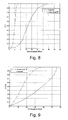
- FIG. 8 shows a comparison between the average user throughput achieved when employing a scheduling method according to a described embodiment, and when using a conventional scheduling method
- FIG. 9 shows a comparison between the average RU throughput achieved when employing a scheduling method according to a described embodiment, and when using a conventional scheduling method.
- a method for scheduling communication links between user devices and signal nodes in a network may comprise:
- the fairness criterion for each user device is based on a ratio of the transmission rate achievable between the user device and the signal node in its respective pair, and the throughput previously achieved by the user device.
- the throughput previously achieved by each user device is measured from a predetermined point in time.
- the throughput previously achieved may be the total throughput achieved by the user device over a predetermined number of scheduling epochs.
- the throughput previously achieved by a user device may be calculated as the mean throughput achieved by the user device over a predetermined number of scheduling epochs.
- a scheduling epoch may correspond to a period between identifying an inactive pair to be made into an active pair and subsequently identifying a further inactive pair to be made into an active pair.
- the step of identifying the inactive pair that when made into an active pair will result in the greatest total fairness criterion includes:
- the step of identifying the inactive pair that, when made into an active pair, will achieve the greatest total fairness criterion includes taking into consideration interference generated by making each respective inactive pair into an active pair. For example, when determining whether an inactive pair is to be made into an active pair, a signal to noise ratio may be calculated for each presently active pair, where the noise includes interference generated by making the respective inactive pair into an active pair.
- Some embodiments include a step of checking whether the greatest total fairness criterion is greater than the sum of the fairness criterions of the active user devices.
- an inactive pair is only made into an active pair if the greatest total fairness criterion achieved by making the inactive pair into an active pair is greater than the sum of the fairness criterions of the active user devices.
- an inactive pair is only made into an active pair if the potential total sum proportional fair ratio for the respective inactive pair is greater than the sum of the proportional fair ratios of the active user devices.
- Some embodiments include a step of checking whether any inactive pairs remain after an inactive pair has been made into an active pair and if so, repeating the earlier steps of the method. In the event that no inactive pairs remain after the inactive pair has been made into an active pair, a new signal channel may be selected, and the steps of the method may then be repeated for the new signal channel.
- active user device(s) are also treated as potential user device(s) of the inactive signal nodes.
- the signal nodes in the respective active and inactive pairs may transmit cooperatively to the potential user device when the inactive pair becomes an active pair.
- the signal transmitted from one signal node may be synchronised with the signal transmitted from the other signal node.
- the signal transmitted from one signal node may be interleaved in time with the signal transmitted from the other signal node. The signal transmitted from the other signal node may, therefore, provide useful signal to the user device, rather than interference.
- the signal channel is a subcarrier signal in an OFDM-based system.
- the inactive pair identified as achieving the greatest total fairness criterion is only made into an active pair in the event that the fairness criterion calculated for each active user device remains above a threshold when the inactive pair is made into an active pair.
- a second embodiment provides a system controller for a multi node communication system for scheduling communication links between signal nodes and user devices, the controller being configured to:
- the fairness criterion for each user device is determined by the system controller based on a ratio of the transmission rate achievable between the user device and the signal node in its respective pair, and the throughput previously achieved by the user device.
- the system controller is configured to calculate the throughput previously achieved by the user device is calculated as the average throughput achieved over a predetermined number of scheduling epochs.
- Each scheduling epoch may correspond to a period between when the system controller identifies an inactive pair to be made into an active pair, and when the system controller subsequently identifies a further inactive pair to be made into an active pair.
- the controller when identifying the inactive pair that will achieve the greatest total fairness criterion when made into an active pair, is configured to:
- the system controller is configured to take into consideration the effect of interference from the active pairs when calculating the achievable rate of transmission for each inactive pair.
- the system controller is configured to check whether the greatest total fairness criterion is greater than the sum of the fairness criterions of each of the active user devices and if so, to make the inactive pair identified in step iii) an active pair. In some embodiments, the system controller is configured to only make the inactive pair identified in step iii) into an active pair if the potential total sum proportional fair ratio for the respective inactive pair is greater than the sum of the proportional fair ratios of the active user devices.
- the controller is configured to check whether any inactive pairs remain after the inactive pair identified as achieving the greatest total fairness criterion has been made into an active pair and if so, to repeat steps i) to iii).
- the system controller in the event that no inactive pairs remain after the inactive pair identified in step iii) has been made into an active pair, is configured to select a new signal channel and to repeat steps i) to iii) for the new signal channel.
- the controller is configured to include active user devices amongst the potential user devices of each inactive signal node.
- the system controller is configured to control the signal nodes in the respective active and inactive pair to cooperatively transmit to the potential user device when the inactive pair becomes an active pair.
- the system controller is configured to make the inactive pair identified as achieving the greatest total fairness criterion into an active pair only in the event that the respective fairness criterion for each active user device remains above a threshold when the inactive pair is made into an active pair.
- system controller may be comprised within a system including a plurality of signal nodes that are controllable by the system controller.
- the system is an OFDM-based system.
- the fairness criterion for a potential user device in an inactive pair is calculated as being the rate of transmission achievable between the potential user device and the respective inactive node.
- a third embodiment of the present invention provides a computer program product stored on a computer-readable media comprising instructions operative to cause a system controller to execute a method according to the first embodiment of the present invention.
- FIG. 1 illustrates an example of DAS in-building deployment, in which there are 3 floors and each floor has one hub unit (HU) connecting with 2 radio remote units (RUs).
- HU hub unit
- RUs radio remote units
- Cloud Radio Access Network In addition to DAS, a new cellular architecture called Cloud Radio Access Network (CRAN) is gaining increasing popularity among major network operators and equipment vendors (e.g. China Mobile, Intel, Huawei, Ericsson). Thanks to the rapid development in computer networks and multi-core processors, real-time cloud computing with centralized processing is becoming a reality. Cloud Computing refers to both the applications delivered as services over the Internet and the hardware and systems software in the data centres that provide those services. There have been proposals (e.g. from Nokia) of offloading computation at mobile clients to the cloud so as to save energy for mobile devices. Recently, China Mobile, IBM, and a few other major ICT companies (e.g.
- CRAN represents a paradigm shift in cellular network architecture (which has remained largely the same for the past 30 years).
- signal processing moves to a powerful cloud, global knowledge of the network conditions and user device traffic may become available. Better coordination of base stations, easier control signalling and better load balancing may therefore be achieved.
- FIG. 3 shows an example of a distributed cellular system comprising inactive and active pairs of signal nodes and user devices.
- signal nodes SN 1 , SN 2 , SN 3 , and SN 4 each form antennas that are deployed over a cell in a distributed manner.
- the antennas are connected to a central control hub unit (not shown in FIG. 3 ).
- user devices UD 1 , UD 2 , UD 3 and UD 4 are shown in FIG. 3 .
- User devices UD 1 to UD 4 may, for example, be mobile phone devices owned by different subscribers to a network.
- Signal node SN 1 is an active signal node that is presently transmitting information to user device UD 1 over a signal channel. Together, signal node SN 1 and UD 1 form an active pair 1 . Similarly, signal node SN 2 and user device UD 2 form a second active pair 3 . Signal node SN 3 is presently inactive, as it is not currently transmitting to any one of the user devices. Similarly, signal node SN 4 is also not transmitting at the present time.
- SN 3 has the potential to transmit to either one of user devices UD 1 or UD 3 .
- SN 3 and UD 1 together form an inactive pair 5
- SN 3 and UD 3 form another inactive pair 7
- SN 4 and UD 3 form an inactive pair and so do SN 4 and UD 4 .
- SN 3 is free to transmit to either UD 1 or UD 3 over the same signal channel as SN 1
- SN 4 is free to transmit to either UD 3 or UD 4 over the same signal channel.
- Embodiments of the present invention provide a means for establishing which of the presently inactive signal nodes shall next be activated to transmit on the signal channel, and which user device shall receive transmissions from that signal node.
- the net effect on the transmission rate of all presently active pairs may be considered. For example, the transmission rate achieved by active pairs of signal nodes and user devices may be reduced as a result of interference introduced when activating a new pair. At the same time, it may be necessary to balance this reduction in transmission rate in presently active pairs against the need to ensure that other, presently inactive, user devices are still able to achieve a minimum degree of throughput.
- proportional fair scheduling is used to establish a fairness criterion for respective user devices.
- the proportional fair scheduling can be expressed to maximize the sum of logarithmic average user device throughput as
- P * arg ⁇ ⁇ max P ⁇ ⁇ ⁇ l ⁇ log ⁇ ⁇ R _ i , k ( P ) ( 1 )
- R i,k (P) is the average throughput of the i th user device over the last k scheduling epochs.
- x i,n (t) is the binary allocation variable that is one if the scheduler assigns the n th signal channel to the i th user device, otherwise zero.
- r i,n (t) is the instantaneous achievable throughput of the i th user device on the n th signal channel.
- the basic idea of carrier-wise proportional solution in (4) is to assign the user devices over the signal channels one by one. For each signal channel, the user device that has the maximal proportional fair ratio
- CRAN and DAS are very similar, since in both architectures there is a central control unit and a number of RUs (cf. FIG. 1 and FIG. 2 ).
- DAS is used to explain an algorithm for allocating signal channels to respective user devices. The same algorithm can be easily applied to CRAN systems too.
- the HU is a central control unit and has all the channel status information (CSI) of the user devices of its RUs, which makes it possible for fast multi-RU dynamic resource allocation/scheduling to reduce the interference. Furthermore, the HU can coordinate the transmissions among the RUs and sometimes enable multiple RUs to cooperatively transmit to the user devices to eliminate interference. To this end, embodiments of the present invention utilise a new radio resource allocation method: joint proportional fair scheduling with cooperative transmission for OFDM-based distributed cellular systems.
- s c is the set of user devices served by the c th RU.
- x c,i,n (t) is the binary allocation variable that is one if scheduler assigns the n th signal channel to the i th user device in the c th RU, otherwise zero.
- r c,i,n (t) is the instantaneous achievable rate of the i th user device on the n th signal channel in the c th RU.
- R c,i,k (P) is the average throughput of the i th user device of the c th RU over the last k scheduling epochs.
- the constraint means each signal channel can be assigned to only one user device within a RU.
- the achievable rate of a user device in a given RU depends on not only the signal from the given RU, but also the interference from other RUs, which makes the optimization in (5) more difficult.
- Finding the optimal solution for (5) is NP-hard and therefore it makes sense to find a practical, suboptimal solution.
- a signal channel-wise suboptimal solution is disclosed to assign the user devices over the signal channels one by one. For each signal channel n, the user devices among the RUs are assigned to maximize the sum of proportional fair ratio as in (6), subject to the constraint that there is at most only one user device assigned to each RU.
- an iterative method is proposed to allocate user devices to the signal channel in a greedy fashion: at each iteration, among the unselected user devices of unselected RUs (i.e. potential user devices in inactive pairs), the user device with the highest positive contribution to the sum of proportional fair ratio of previously selected user devices (i.e. active devices) will be selected. Then the next iteration will be carried out until either every RU is assigned a user device or there is no further positive contribution to the sum of proportional fair ratio.
- the whole procedure includes the following steps.
- C n the set of RUs having user devices selected at signal channel n, and name the RUs in the set as selected RUs.
- U n is the set of selected user devices for signal channel n.
- ⁇ C n ,U n ⁇ is a pair set of the selected RUs and user devices (i.e. the set of active pairs).
- ⁇ is the sum of the proportional fair ratio of current selected (i.e. active) user devices.
- K is the set of total RUs.
- ⁇ is a null set.
- S c is the set of user devices in the c th RU.
- are the cardinality of the set K and C n respectively.
- Step 2 For each unselected RU c ⁇ C n
- T c , i r c , i , n ( t ) R _ c , i , k ( t - 1 ) + ⁇ ⁇ c ′ , j ⁇ ⁇ ⁇ C n , U n ⁇ ⁇ r c ′ , j , n ⁇ c ( t ) R _ c ′ , j , k ( t - 1 ) .
- Step 3 Check whether the contribution to the sum of proportional fair ratio is positive. If the contribution to the sum of proportional fair ratio is positive, i.e. T c*,i* > ⁇ , then:
- Step 4 Check whether the set of unselected RU is empty (i.e. check if there are any inactive pairs remaining). If it is not empty, repeat steps 2 and 3, otherwise, proceed to the next signal channel. The above procedure is shown in FIG. 4 .
- the cell edge user devices of RUs may experience severe interference.
- the above resource allocation method can be slightly revised to further mitigate the multi-RU interference.
- the equation used to determine which of the potential user devices is to be made into an active user device in each iteration can be changed to ensure that the presently active user devices do not suffer a degraded performance as a result of the inactive pair becoming an active pair.
- each RU is physically an analogue antenna array and is connected directly with the HU unit.
- the HU can have all the CQI information from all the user devices of its RUs and acts as a central control unit. This architecture makes cooperative transmission implementable.
- a user device UE sits in the cell of RU- 1 , but suffers from the interference from RU- 2 .
- the signal transmitted from RU- 2 to the user device UE can provide a useful addition to the signal transmitted from RU- 1 to the user device, rather than the two signals simply interfering with one another.
- the original RU that serves the user device UE may be called the serving RU and the RU that cooperatively transmits to the user device UE is called the user device UE's slave RU.
- the above carrier-wise resource allocation method can be revised to integrate cooperative transmission as follows.
- the previously selected user devices i.e. the active users
- the inactive pair that offers the highest positive contribution to the sum of proportional fair ratio of previously selected (i.e. active) user devices will be selected to become an active pair.
- the newly selected user device is a previously selected (active) user device
- the user device will then be in communication with 2 signal nodes, which will transmit to that user device in a cooperative manner.
- the next iteration will be carried out until either every inactive RU has been assigned a user device, or there is no further positive contribution to the sum of the proportional fair ratio.
- the whole procedure includes the following steps:
- Step 2 For each unselected RU c ⁇ C n
- T c , g r c , g , n ( t ) R _ c , g , k ( t - 1 ) + ⁇ ⁇ c ′ , j ⁇ ⁇ ⁇ C n , U n ⁇ ⁇ r c ′ , j , n ⁇ c ( t ) R _ c ′ , j , k ( t - 1 ) , for ⁇ ⁇ g ⁇ S c
- T c , g r c , g , n ⁇ + c ( t ) R _ c , g , k ( t - 1 ) + ⁇ ⁇ c ′ , j ⁇ ⁇ ⁇ C n , U n ⁇ j ⁇ g ⁇ r c ′ , j , n ⁇ c ( t ) R _ c ′ , j , k ( t - 1 ) , for ⁇ ⁇ ⁇ c ′′ , g ⁇ ⁇ ⁇ C n , U n ⁇ , assuming that the signal node RU c cooperatively transmits to the previously selected (active) user device, i.e. ⁇ c′,g ⁇ C n ,U n ⁇ .
- Step 3 Check whether the contribution to the sum of proportional fair ratio is positive. If the contribution to the sum of proportional fair ratio is positive i.e. T c*,g* > ⁇ , then:
- Step 4 Check whether the set of unselected RU is empty (i.e. check if there are any inactive pairs remaining). If it is not empty, repeat steps 2 and 3, otherwise, proceed to the next signal channel. The procedure is shown in FIG. 6 .
- Each signal channel may be a subcarrier, but is not limited to the subchannel or chunk level, where the subchannel or chunk is a group of multiple subcarriers.
Landscapes
- Engineering & Computer Science (AREA)
- Computer Networks & Wireless Communication (AREA)
- Signal Processing (AREA)
- Quality & Reliability (AREA)
- Mobile Radio Communication Systems (AREA)
Abstract
Description
-
- identifying one or more active signal node/user device pairs, wherein each active pair comprises a signal node that is presently communicating with a respective active user device over a signal channel,
- identifying one or more inactive signal node/user device pairs, wherein each inactive pair comprises an inactive signal node that is not presently communicating over the signal channel and a potential user device that is capable of communicating with the inactive signal node over the signal channel, and
- identifying one of the inactive pairs that, when made into an active pair, will achieve the greatest total fairness criterion, wherein the total fairness criterion is a sum of a fairness criterion for the potential user device in the inactive pair in question and a fairness criterion for each of the active user devices in the event that the respective inactive pair becomes an active pair,
- wherein the fairness criterion for each user device is determined based on the transmission rate achievable between the user device and the signal node in its respective pair.
-
- calculating an achievable rate of transmission over the signal channel for each inactive pair,
- calculating an achievable rate of transmission over the signal channel for each active pair for each case in which a respective inactive pair becomes an active pair,
- calculating a proportional fair ratio for the potential user device in each inactive pair in the event that the respective inactive pair becomes an active pair,
- calculating a proportional fair ratio for each active user device for each case in which an inactive pair becomes an active pair,
- for each inactive pair, adding the proportional fair ratio calculated for the potential user device in the inactive pair to the proportional fair ratio calculated for each active user device in the event that the respective inactive pair becomes an active pair to obtain a potential total sum proportional fair ratio for the case in which the respective inactive pair becomes an active pair, and
- identifying the inactive pair that when active provides the largest potential total sum proportional fair ratio.
-
- i) identify one or more active signal node/user device pairs, wherein each active pair comprises a signal node that is presently communicating with a respective active user device over a signal channel,
- ii) identify one or more inactive signal node/user device pairs, wherein each inactive pair comprises an inactive signal node that is not presently communicating over the signal channel and a potential user device that is capable of communicating with the inactive signal node over the signal channel, and
- iii) identify one of the inactive pairs that, when made into an active pair, will achieve the greatest total fairness criterion, wherein the total fairness criterion is a sum of a fairness criterion for the potential user device in the inactive pair in question and a fairness criterion for each of the active user devices in the event that the respective inactive pair becomes an active pair,
- wherein the fairness criterion for each user device is determined by the system controller based on the transmission rate achievable between the user device and the signal node in its respective pair.
-
- iv) calculate an achievable rate of transmission over the signal channel for each inactive pair,
- v) calculate an achievable rate of transmission over the signal channel for each active pair for each case in which a respective inactive pair becomes an active pair,
- vi) calculate a proportional fair ratio for the potential user device in each inactive pair in the event that the respective inactive pair becomes an active pair,
- vii) calculate a proportional fair ratio for each active user device for each case in which an inactive pair becomes an active pair,
- viii) add the results obtained in steps vi) and vii) to obtain a potential total sum proportional fair ratio for each case in which a respective inactive pair becomes an active pair, and
- ix) identify the inactive pair that when active provides the largest total sum proportional fair ratio.
where
where xi,n (t) is the binary allocation variable that is one if the scheduler assigns the nth signal channel to the ith user device, otherwise zero. ri,n (t) is the instantaneous achievable throughput of the ith user device on the nth signal channel.
as in (4) will be assigned.
where sc is the set of user devices served by the cth RU. xc,i,n (t) is the binary allocation variable that is one if scheduler assigns the nth signal channel to the ith user device in the cth RU, otherwise zero. rc,i,n (t) is the instantaneous achievable rate of the ith user device on the nth signal channel in the cth RU.
Cn=φ;
Un=φ;
{Cn,Un}={φ,φ}
Ω=0
-
- a) Set the sum of the proportional fair ratio of current selected user devices (active user devices) as Ω=Tc*,i*.
- b) Add the newly selected user device to the set of active user devices as Un=Un∪i*.
- c) Add the RU serving the newly selected user device to the set of selected RUs Cn=Cn∪c*.
- d) Update the set of unselected RU as
C n=KCn
-
- In some embodiments, the user device among the potential user devices of inactive RUs (c*,i*) that has the highest contribution to the sum of proportional fair ratio Tc*,i*
is only made into an active user in the event that:
rc′,j,n←c (t)>γ∀{c′,j}ε{Cn,Un}
where γ is the minimal QoS requirement or data rate with minimal MCS support. In other words, where the effect of making an inactive pair into an active pair is to cause the transmission rate achievable for presently active users to fall below a threshold level, the inactive pair is not made into an active pair.
Cn=φ
Un=φ
{Cn,Un}={φ,φ}
Ω=0
-
- assuming that the user device for the unselected RU c (i.e. gεSc) is added.
- e) Calculate the total sum of proportional fair ratio as
assuming that the signal node RU c cooperatively transmits to the previously selected (active) user device, i.e. {c′,g}ε{Cn,Un}.
-
- a) Set the sum of the proportional fair ratio of current selected user devices (active user devices) as Ω=Tc*,g*
- b) Add the newly selected user device to the set of selected user devices (active user devices) as Un=Un∪g*
- c) Add the RU serving the newly selected user device to the set of selected RUs Cn=Cn∪c*
- c) Add the RU serving the newly selected user device to the set of selected RUs Cn=Cn∪c*
- d) Update the set of unselected RU as
C n=KCn - e) Set xc*,g*,n (t)=1
Claims (24)
Applications Claiming Priority (2)
| Application Number | Priority Date | Filing Date | Title |
|---|---|---|---|
| GB1122420.1 | 2011-12-23 | ||
| GB201122420A GB2497989B (en) | 2011-12-23 | 2011-12-23 | Radio resource management for distributed cellular systems |
Publications (2)
| Publication Number | Publication Date |
|---|---|
| US20130163539A1 US20130163539A1 (en) | 2013-06-27 |
| US9031024B2 true US9031024B2 (en) | 2015-05-12 |
Family
ID=45695055
Family Applications (1)
| Application Number | Title | Priority Date | Filing Date |
|---|---|---|---|
| US13/722,016 Expired - Fee Related US9031024B2 (en) | 2011-12-23 | 2012-12-20 | Radio resource management for distributed cellular systems |
Country Status (3)
| Country | Link |
|---|---|
| US (1) | US9031024B2 (en) |
| JP (1) | JP5558551B2 (en) |
| GB (1) | GB2497989B (en) |
Families Citing this family (6)
| Publication number | Priority date | Publication date | Assignee | Title |
|---|---|---|---|---|
| US9125047B2 (en) * | 2012-07-26 | 2015-09-01 | Nec Laboratories America, Inc. | Cloud-based radio access network for small cells |
| US20140213275A1 (en) * | 2013-01-30 | 2014-07-31 | Acer Incorporated | Methods of Performing Radio Resource Management, Network Node, Mobile Device, Base Station, and Wireless Communication System Using the Same Methods |
| WO2015120463A1 (en) * | 2014-02-10 | 2015-08-13 | Big Belly Solar, Inc. | Dynamically adjustable nodes in a sensor network |
| EP3163782B1 (en) | 2015-10-27 | 2018-07-25 | Telefonica, S.A. | Method to perform joint scheduling in the downlink or in the uplink of a centralized ofdm radio access network for a plurality of users considering time, frequency and space domains, scheduler device thereof and computer program products |
| EP3744074B1 (en) * | 2018-01-26 | 2024-12-11 | Outdoor Wireless Networks LLC | Cloud network implementation for a distributed antenna system control plane |
| CN112419699A (en) * | 2020-11-04 | 2021-02-26 | 国网山西省电力公司营销服务中心 | Resource allocation method and system suitable for power system |
Citations (3)
| Publication number | Priority date | Publication date | Assignee | Title |
|---|---|---|---|---|
| US7450577B2 (en) * | 2000-12-01 | 2008-11-11 | Telefonaktiebolaget L M Ericsson (Publ) | Flexible inter-network communication scheduling |
| WO2010019613A1 (en) | 2008-08-13 | 2010-02-18 | Ntt Docomo, Inc. | A method of combined user and coordination pattern scheduling over varying antenna and base-station coordination patterns in a multi-cell environment |
| JP2010246114A (en) | 2009-03-31 | 2010-10-28 | Ntt Docomo Inc | Multi-cell cooperative transmission method |
Family Cites Families (4)
| Publication number | Priority date | Publication date | Assignee | Title |
|---|---|---|---|---|
| US20040258026A1 (en) * | 2003-06-19 | 2004-12-23 | Lau Kin Nang | Method of uplink scheduling for multiple antenna systems |
| KR100871257B1 (en) * | 2007-02-23 | 2008-11-28 | 삼성전자주식회사 | Combined Scheduling Method and Apparatus for Improving Frequency Efficiency and Fairness in Multichannel Distributed Antenna Systems Using Frequency Recycling and Joint Power Control |
| JP5480916B2 (en) * | 2009-02-03 | 2014-04-23 | コーニング ケーブル システムズ リミテッド ライアビリティ カンパニー | Fiber optic based distributed antenna system, components, and related methods for calibration thereof |
| GB2482316B (en) * | 2010-07-28 | 2012-09-19 | Toshiba Res Europ Ltd | Network resource management methods and apparatus |
-
2011
- 2011-12-23 GB GB201122420A patent/GB2497989B/en not_active Expired - Fee Related
-
2012
- 2012-12-20 US US13/722,016 patent/US9031024B2/en not_active Expired - Fee Related
- 2012-12-25 JP JP2012280700A patent/JP5558551B2/en not_active Expired - Fee Related
Patent Citations (5)
| Publication number | Priority date | Publication date | Assignee | Title |
|---|---|---|---|---|
| US7450577B2 (en) * | 2000-12-01 | 2008-11-11 | Telefonaktiebolaget L M Ericsson (Publ) | Flexible inter-network communication scheduling |
| WO2010019613A1 (en) | 2008-08-13 | 2010-02-18 | Ntt Docomo, Inc. | A method of combined user and coordination pattern scheduling over varying antenna and base-station coordination patterns in a multi-cell environment |
| JP2012500522A (en) | 2008-08-13 | 2012-01-05 | 株式会社エヌ・ティ・ティ・ドコモ | A method for scheduling combinations of users and cooperative patterns according to changes in cooperative patterns of antennas and base stations in a multi-cell environment |
| US8229443B2 (en) * | 2008-08-13 | 2012-07-24 | Ntt Docomo, Inc. | Method of combined user and coordination pattern scheduling over varying antenna and base-station coordination patterns in a multi-cell environment |
| JP2010246114A (en) | 2009-03-31 | 2010-10-28 | Ntt Docomo Inc | Multi-cell cooperative transmission method |
Non-Patent Citations (1)
| Title |
|---|
| Office Action issued Nov. 12, 2013 in Japanese Application No. 2012-280700 (With English Translation). |
Also Published As
| Publication number | Publication date |
|---|---|
| GB2497989A (en) | 2013-07-03 |
| GB2497989B (en) | 2014-02-19 |
| US20130163539A1 (en) | 2013-06-27 |
| JP2013146058A (en) | 2013-07-25 |
| GB201122420D0 (en) | 2012-02-08 |
| JP5558551B2 (en) | 2014-07-23 |
Similar Documents
| Publication | Publication Date | Title |
|---|---|---|
| CN111447619B (en) | A method for joint task offloading and resource allocation in mobile edge computing networks | |
| US10038525B2 (en) | Management of coordinated multi-point communication | |
| KR102208117B1 (en) | Method for managing wireless resource and apparatus therefor | |
| US9379836B2 (en) | Resource allocation server and communication system for cloud-based radio access network | |
| CN103959689B (en) | Method and apparatus for interference management | |
| US9107126B2 (en) | Radio resource control for dual-access-technology cells | |
| US10470137B2 (en) | Power allocation for device-to-device communication underlaying cellular networks | |
| US9031024B2 (en) | Radio resource management for distributed cellular systems | |
| JP2002044718A (en) | Method for channel assignment and processing method of request for wireless service | |
| CN104113920A (en) | Association and resource partitioning in a wireless network with relays | |
| US10831553B2 (en) | System and method for fair resource allocation | |
| US20140161058A1 (en) | Carrier Aggregation | |
| CN104770004B (en) | A kind of communication system and method | |
| US12035144B2 (en) | Spectrum management device, electronic device, radio communication method, and storage medium | |
| US12231376B2 (en) | Time division duplex pattern configuration for cellular networks | |
| CN109788485A (en) | The method for being used to help solve the cluster optimization of the border issue in communication system | |
| US9253781B2 (en) | Scheduling in consideration of terminal groups in a mobile communication system | |
| Kılıç et al. | Joint channel and power allocation for device-to-device underlay | |
| WO2014117377A1 (en) | Method and apparatus for resource allocation for device-to-device communication | |
| WO2019062822A1 (en) | Resource allocation method and server | |
| Rahman et al. | Exploring Missed Spectrum Opportunities for Enhancing the Mid-band Spectrum Utilization | |
| US10044414B2 (en) | Methods and apparatus for coordinated multipoint communication | |
| TWI755891B (en) | Communication system, method and computer program product thereof | |
| Zhang et al. | User satisfaction-aware radio resource management in ultra-dense small cell networks | |
| CN106911364B (en) | Method and device for allocating remote antennas in cloud wireless access network |
Legal Events
| Date | Code | Title | Description |
|---|---|---|---|
| AS | Assignment |
Owner name: KABUSHIKI KAISHA TOSHIBA, JAPAN Free format text: ASSIGNMENT OF ASSIGNORS INTEREST;ASSIGNORS:CAO, FENGMING;FAN, ZHONG;REEL/FRAME:029882/0122 Effective date: 20130214 |
|
| STCF | Information on status: patent grant |
Free format text: PATENTED CASE |
|
| FEPP | Fee payment procedure |
Free format text: MAINTENANCE FEE REMINDER MAILED (ORIGINAL EVENT CODE: REM.); ENTITY STATUS OF PATENT OWNER: LARGE ENTITY |
|
| LAPS | Lapse for failure to pay maintenance fees |
Free format text: PATENT EXPIRED FOR FAILURE TO PAY MAINTENANCE FEES (ORIGINAL EVENT CODE: EXP.); ENTITY STATUS OF PATENT OWNER: LARGE ENTITY |
|
| STCH | Information on status: patent discontinuation |
Free format text: PATENT EXPIRED DUE TO NONPAYMENT OF MAINTENANCE FEES UNDER 37 CFR 1.362 |
|
| FP | Lapsed due to failure to pay maintenance fee |
Effective date: 20190512 |