US9030448B2 - Information storage medium and image control system for multi-touch resistive touch panel display - Google Patents
Information storage medium and image control system for multi-touch resistive touch panel display Download PDFInfo
- Publication number
- US9030448B2 US9030448B2 US12/884,789 US88478910A US9030448B2 US 9030448 B2 US9030448 B2 US 9030448B2 US 88478910 A US88478910 A US 88478910A US 9030448 B2 US9030448 B2 US 9030448B2
- Authority
- US
- United States
- Prior art keywords
- operation state
- section
- touch
- area
- indicated
- Prior art date
- Legal status (The legal status is an assumption and is not a legal conclusion. Google has not performed a legal analysis and makes no representation as to the accuracy of the status listed.)
- Expired - Fee Related, expires
Links
Images


Classifications
-
- G—PHYSICS
- G06—COMPUTING OR CALCULATING; COUNTING
- G06F—ELECTRIC DIGITAL DATA PROCESSING
- G06F3/00—Input arrangements for transferring data to be processed into a form capable of being handled by the computer; Output arrangements for transferring data from processing unit to output unit, e.g. interface arrangements
- G06F3/01—Input arrangements or combined input and output arrangements for interaction between user and computer
- G06F3/03—Arrangements for converting the position or the displacement of a member into a coded form
- G06F3/041—Digitisers, e.g. for touch screens or touch pads, characterised by the transducing means
- G06F3/0416—Control or interface arrangements specially adapted for digitisers
- G06F3/0418—Control or interface arrangements specially adapted for digitisers for error correction or compensation, e.g. based on parallax, calibration or alignment
- G06F3/04186—Touch location disambiguation
-
- G—PHYSICS
- G06—COMPUTING OR CALCULATING; COUNTING
- G06F—ELECTRIC DIGITAL DATA PROCESSING
- G06F3/00—Input arrangements for transferring data to be processed into a form capable of being handled by the computer; Output arrangements for transferring data from processing unit to output unit, e.g. interface arrangements
- G06F3/01—Input arrangements or combined input and output arrangements for interaction between user and computer
- G06F3/03—Arrangements for converting the position or the displacement of a member into a coded form
- G06F3/041—Digitisers, e.g. for touch screens or touch pads, characterised by the transducing means
- G06F3/0416—Control or interface arrangements specially adapted for digitisers
- G06F3/0418—Control or interface arrangements specially adapted for digitisers for error correction or compensation, e.g. based on parallax, calibration or alignment
-
- G—PHYSICS
- G06—COMPUTING OR CALCULATING; COUNTING
- G06F—ELECTRIC DIGITAL DATA PROCESSING
- G06F3/00—Input arrangements for transferring data to be processed into a form capable of being handled by the computer; Output arrangements for transferring data from processing unit to output unit, e.g. interface arrangements
- G06F3/01—Input arrangements or combined input and output arrangements for interaction between user and computer
- G06F3/048—Interaction techniques based on graphical user interfaces [GUI]
- G06F3/0484—Interaction techniques based on graphical user interfaces [GUI] for the control of specific functions or operations, e.g. selecting or manipulating an object, an image or a displayed text element, setting a parameter value or selecting a range
-
- A—HUMAN NECESSITIES
- A63—SPORTS; GAMES; AMUSEMENTS
- A63F—CARD, BOARD, OR ROULETTE GAMES; INDOOR GAMES USING SMALL MOVING PLAYING BODIES; VIDEO GAMES; GAMES NOT OTHERWISE PROVIDED FOR
- A63F2300/00—Features of games using an electronically generated display having two or more dimensions, e.g. on a television screen, showing representations related to the game
- A63F2300/10—Features of games using an electronically generated display having two or more dimensions, e.g. on a television screen, showing representations related to the game characterized by input arrangements for converting player-generated signals into game device control signals
- A63F2300/1068—Features of games using an electronically generated display having two or more dimensions, e.g. on a television screen, showing representations related to the game characterized by input arrangements for converting player-generated signals into game device control signals being specially adapted to detect the point of contact of the player on a surface, e.g. floor mat, touch pad
- A63F2300/1075—Features of games using an electronically generated display having two or more dimensions, e.g. on a television screen, showing representations related to the game characterized by input arrangements for converting player-generated signals into game device control signals being specially adapted to detect the point of contact of the player on a surface, e.g. floor mat, touch pad using a touch screen
-
- A—HUMAN NECESSITIES
- A63—SPORTS; GAMES; AMUSEMENTS
- A63F—CARD, BOARD, OR ROULETTE GAMES; INDOOR GAMES USING SMALL MOVING PLAYING BODIES; VIDEO GAMES; GAMES NOT OTHERWISE PROVIDED FOR
- A63F2300/00—Features of games using an electronically generated display having two or more dimensions, e.g. on a television screen, showing representations related to the game
- A63F2300/30—Features of games using an electronically generated display having two or more dimensions, e.g. on a television screen, showing representations related to the game characterized by output arrangements for receiving control signals generated by the game device
- A63F2300/301—Features of games using an electronically generated display having two or more dimensions, e.g. on a television screen, showing representations related to the game characterized by output arrangements for receiving control signals generated by the game device using an additional display connected to the game console, e.g. on the controller
-
- G—PHYSICS
- G06—COMPUTING OR CALCULATING; COUNTING
- G06F—ELECTRIC DIGITAL DATA PROCESSING
- G06F2203/00—Indexing scheme relating to G06F3/00 - G06F3/048
- G06F2203/048—Indexing scheme relating to G06F3/048
- G06F2203/04808—Several contacts: gestures triggering a specific function, e.g. scrolling, zooming, right-click, when the user establishes several contacts with the surface simultaneously; e.g. using several fingers or a combination of fingers and pen
-
- G—PHYSICS
- G06—COMPUTING OR CALCULATING; COUNTING
- G06F—ELECTRIC DIGITAL DATA PROCESSING
- G06F3/00—Input arrangements for transferring data to be processed into a form capable of being handled by the computer; Output arrangements for transferring data from processing unit to output unit, e.g. interface arrangements
- G06F3/01—Input arrangements or combined input and output arrangements for interaction between user and computer
- G06F3/03—Arrangements for converting the position or the displacement of a member into a coded form
- G06F3/041—Digitisers, e.g. for touch screens or touch pads, characterised by the transducing means
- G06F3/045—Digitisers, e.g. for touch screens or touch pads, characterised by the transducing means using resistive elements, e.g. a single continuous surface or two parallel surfaces put in contact
-
- G—PHYSICS
- G06—COMPUTING OR CALCULATING; COUNTING
- G06F—ELECTRIC DIGITAL DATA PROCESSING
- G06F3/00—Input arrangements for transferring data to be processed into a form capable of being handled by the computer; Output arrangements for transferring data from processing unit to output unit, e.g. interface arrangements
- G06F3/01—Input arrangements or combined input and output arrangements for interaction between user and computer
- G06F3/048—Interaction techniques based on graphical user interfaces [GUI]
- G06F3/0487—Interaction techniques based on graphical user interfaces [GUI] using specific features provided by the input device, e.g. functions controlled by the rotation of a mouse with dual sensing arrangements, or of the nature of the input device, e.g. tap gestures based on pressure sensed by a digitiser
- G06F3/0488—Interaction techniques based on graphical user interfaces [GUI] using specific features provided by the input device, e.g. functions controlled by the rotation of a mouse with dual sensing arrangements, or of the nature of the input device, e.g. tap gestures based on pressure sensed by a digitiser using a touch-screen or digitiser, e.g. input of commands through traced gestures
- G06F3/04886—Interaction techniques based on graphical user interfaces [GUI] using specific features provided by the input device, e.g. functions controlled by the rotation of a mouse with dual sensing arrangements, or of the nature of the input device, e.g. tap gestures based on pressure sensed by a digitiser using a touch-screen or digitiser, e.g. input of commands through traced gestures by partitioning the display area of the touch-screen or the surface of the digitising tablet into independently controllable areas, e.g. virtual keyboards or menus
Definitions
- the present invention relates to an information storage medium and an image control system.
- An image control system (image control device) including a touch panel has been known.
- An image control system including a touch panel may acquire the position coordinates on the operation surface based on the detection value from the touch panel, and control the image based on the position coordinates.
- a touch panel may output a detection value corresponding to one position when the touch operation has been performed at one position on the operation surface, and output a detection value corresponding to the midpoint between two positions when the touch operation has been performed at two positions on the operation surface.
- an image control system including such a touch panel acquires the position coordinates of the touch operation when the touch operation has been performed at one position on the operation surface, and controls the image based on the position of the touch operation.
- the image control system acquires the position coordinates of a position differing from the position of the touch operation. Therefore, the image control system cannot control the image based on the position of the touch operation.
- a related-art image control system using the above touch panel does not perform a process based on the acquired position coordinates when the touch operation has been performed at two positions.
- a program stored in a non-transitory computer-readable information storage medium controlling an image displayed on a display screen of a display section based on a detection value output from a detection section, the detection section outputting the detection value corresponding to a first position when an operation state of a touch operation performed on an operation surface is a first operation state in which a first touch operation is performed at the first position on the operation surface, and outputting the detection value corresponding to a midpoint between the first position and a second position when the operation state is a second operation state in which a second touch operation is performed at the second position on the operation surface in addition to the first touch operation, the program causing a computer to function as:
- an acquisition section that acquires a detected position based on the detection value, the detected position indicating a position on the operation surface
- a state determination section that determines whether the operation state is the first operation state or the second operation state based on the detection value
- a correction section that calculates a corrected position when the operation state is the second operation state, one endpoint being indicated by the detected position acquired in the first operation state, a midpoint being indicated by the detected position acquired in the second operation state, and the other endpoint being indicated by the corrected position;
- a display control section that controls the image based on the corrected position.
- a program stored in a non-transitory computer-readable information storage medium controlling an image displayed on a display screen of a display section based on a detection value output from a detection section, the detection section outputting the detection value corresponding to a first position when an operation state of a touch operation performed on an operation surface is a first operation state in which a first touch operation is performed at the first position on the operation surface, and outputting the detection value corresponding to a midpoint between the first position and a second position when the operation state is a second operation state in which a second touch operation is performed at the second position on the operation surface in addition to the first touch operation, the program causing a computer to function as:
- an acquisition section that acquires a detected position based on the detection value, the detected position indicating a position on the operation surface
- a state determination section that determines whether the operation state is the first operation state or the second operation state based on the detection value
- a correction section that calculates a corrected position when the operation state is the second operation state, one endpoint being indicated by the detected position in the first operation state, a midpoint being indicated by the detected position in the second operation state, and the other endpoint being indicated by the corrected position;
- a position determination section that determines whether or not the corrected position coincides with a given position
- a display control section that controls the image.
- a non-transitory computer-readable information storage medium for storing the program.
- an image control system that controls an image displayed on a display screen of a display section based on a detection value output from a detection section, the detection section outputting the detection value corresponding to a first position when an operation state of a touch operation performed on an operation surface is a first operation state in which a first touch operation is performed at the first position on the operation surface, and outputting the detection value corresponding to a midpoint between the first position and a second position when the operation state is a second operation state in which a second touch operation is performed at the second position on the operation surface in addition to the first touch operation, the image control system comprising:
- an acquisition section that acquires a detected position based on the detection value, the detected position indicating a position on the operation surface
- a state determination section that determines whether the operation state is the first operation state or the second operation state based on the detection value
- a correction section that calculates a corrected position when the operation state is the second operation state, one endpoint being indicated by the detected position acquired in the first operation state, a midpoint being indicated by the detected position acquired in the second operation state, and the other endpoint being indicated by the corrected position;
- a display control section that controls the image based on the corrected position.
- an image control system that controls an image displayed on a display screen of a display section based on a detection value output from a detection section, the detection section outputting the detection value corresponding to a first position when an operation state of a touch operation performed on an operation surface is a first operation state in which a first touch operation is performed at the first position on the operation surface, and outputting the detection value corresponding to a midpoint between the first position and a second position when the operation state is a second operation state in which a second touch operation is performed at the second position on the operation surface in addition to the first touch operation, the image control system comprising:
- an acquisition section that acquires a detected position based on the detection value, the detected position indicating a position on the operation surface
- a state determination section that determines whether the operation state is the first operation state or the second operation state based on the detection value
- a correction section that calculates a corrected position when the operation state is the second operation state, one endpoint being indicated by the detected position in the first operation state, a midpoint being indicated by the detected position in the second operation state, and the other endpoint being indicated by the corrected position;
- a position determination section that determines whether or not the corrected position coincides with a given position
- a display control section that controls the image.
- FIG. 1 is an external view illustrating the appearance of a game system according to one embodiment of the invention.
- FIG. 2 is an exploded view illustrating a touch panel of a game system according to one embodiment of the invention.
- FIGS. 3A to 3D are diagrams illustrating a process performed by a game system according to one embodiment of the invention.
- FIG. 4 is a functional block diagram illustrating a game system according to one embodiment of the invention.
- FIG. 5 is a diagram illustrating an example of an image displayed on a game system according to one embodiment of the invention.
- FIG. 6 is a diagram illustrating a process performed by a game system according to one embodiment of the invention.
- FIG. 7 is a flowchart illustrating the flow of a process performed by a game system according to one embodiment of the invention.
- FIG. 8 is a flowchart illustrating the flow of a process performed by a game system according to one embodiment of the invention.
- FIG. 9 is a flowchart illustrating the flow of a process performed by a game system according to one embodiment of the invention.
- FIGS. 10A to 10D are diagrams illustrating a process performed by a game system according to one embodiment of the invention.
- FIGS. 11A to 11C are diagrams illustrating an example of an image displayed on a game system according to one embodiment of the invention.
- FIGS. 12A to 12E are diagrams illustrating an example of an image displayed on a game system according to one embodiment of the invention.
- FIG. 13 is a diagram illustrating an example of an image displayed on a game system according to one embodiment of the invention.
- FIG. 14 is a diagram illustrating an example of an image displayed on a game system according to one embodiment of the invention.
- the invention may provide a program, an information storage medium and an image control system that enable a process to be performed based on the position of the touch operation even when the touch operation has been performed at two positions.
- One embodiment of the invention relates to an image control system that controls an image displayed on a display screen of a display section based on a detection value output from a detection section, the detection section outputting the detection value corresponding to a first position when an operation state of a touch operation performed on an operation surface is a first operation state in which a first touch operation is performed at the first position on the operation surface, and outputting the detection value corresponding to a midpoint between the first position and a second position when the operation state is a second operation state in which a second touch operation is performed at the second position on the operation surface in addition to the first touch operation, the image control system comprising:
- an acquisition section that acquires a detected position based on the detection value, the detected position indicating a position on the operation surface
- a state determination section that determines whether the operation state is the first operation state or the second operation state based on the detection value
- a correction section that calculates a corrected position when the operation state is the second operation state, one endpoint being indicated by the detected position acquired in the first operation state, a midpoint being indicated by the detected position acquired in the second operation state, and the other endpoint being indicated by the corrected position;
- a display control section that controls the image based on the corrected position.
- Another embodiment of the invention relates to a program that causes a computer to function as each of the above sections and a non-transitory computer-readable information storage medium for storing such a program.
- the corrected position when the first position in the first operation state is maintained when the operation state has transitioned to the second operation state, the corrected position can be calculated so that the corrected position coincides with the second position. Therefore, when the touch operation has been performed at the second position in addition to the first position, the image can be controlled based on the second position.
- Another embodiment of the invention relates to an image control system that controls an image displayed on a display screen of a display section based on a detection value output from a detection section, the detection section outputting the detection value corresponding to a first position when an operation state of a touch operation performed on an operation surface is a first operation state in which a first touch operation is performed at the first position on the operation surface, and outputting the detection value corresponding to a midpoint between the first position and a second position when the operation state is a second operation state in which a second touch operation is performed at the second position on the operation surface in addition to the first touch operation, the image control system comprising:
- an acquisition section that acquires a detected position based on the detection value, the detected position indicating a position on the operation surface
- a state determination section that determines whether the operation state is the first operation state or the second operation state based on the detection value
- a correction section that calculates a corrected position when the operation state is the second operation state, one endpoint being indicated by the detected position in the first operation state, a midpoint being indicated by the detected position in the second operation state, and the other endpoint being indicated by the corrected position;
- a position determination section that determines whether or not the corrected position coincides with a given position
- a display control section that controls the image.
- Another embodiment of the invention relates to a program that causes a computer to function as each of the above sections and a non-transitory computer-readable information storage medium for storing such a program.
- the corrected position when the first position in the first operation state is maintained when the operation state has transitioned to the second operation state, the corrected position can be calculated so that the corrected position coincides with the second position. Therefore, when the touch operation has been performed at the second position in addition to the first position, whether or not the second position coincides with a given position can be determined.
- the display control section may control the image based on a determination result of the position determination section.
- the correction section may calculate the corrected position when a new detected position has been acquired in the second operation state, one endpoint being indicated by the detected position acquired in the first operation state, a midpoint being indicated by the detected position currently acquired in the second operation state, and the other endpoint being indicated by the corrected position.
- the corrected position when the first position in the first operation state is maintained when the second position has changed in the second operation state, the corrected position can be calculated so that the corrected position coincides with the second position.
- the correction section may calculate the corrected position when a new detected position has been acquired in the second operation state, one endpoint being indicated by the corrected position initially calculated in the second operation state, a midpoint being indicated by the detected position currently acquired in the second operation state, and the other endpoint being indicated by the corrected position.
- the corrected position when the first position has changed in the second operation state while the second position is maintained, the corrected position can be calculated so that the corrected position coincides with the first position.
- the image control system may further comprise a movement information calculation section that calculates movement information about the corrected position when the corrected position has changed, wherein the display control section may control the image based on the movement information about the corrected position.
- the program may further cause a computer to function as a movement information calculation section that calculates movement information about the corrected position when the corrected position has changed, wherein the display control section may control the image based on the movement information about the corrected position.
- the program may cause the computer to further function as a movement information calculation section that calculates movement information about the corrected position when the corrected position has changed, wherein the display control section may control the image based on the movement information about the corrected position.
- the image control system may further comprise a period measurement section that measures a period of the first operation state, wherein the display control section may control the image based on the period of the first operation state.
- the program may further cause a computer to function as a period measurement section that measures a period of the first operation state, wherein the display control section may control the image based on the period of the first operation state.
- the program may cause the computer to further function as a period measurement section that measures a period of the first operation state, wherein the display control section may control the image based on the period of the first operation state.
- the display control section may display a display object in an overlapping area of the display screen that overlaps the operation surface, the display object identifying a first area where the first touch operation should be performed, and a second area where the second touch operation should be performed.
- the state determination section may determine that the operation state is a non-operation state in which the touch operation is not performed on the operation surface when the detection value is not output, may determine that the operation state is the first operation state when the detection value has been output when the operation state is the non-operation state, and may determine that the operation state is the second operation state when a moving amount of the detected position has exceeded a first threshold value when the operation state is the first operation state.
- the state determination section may determine that the operation state is the first operation state when a moving amount of the detected position has exceeded a second threshold value when the operation state is the second operation state.
- FIG. 1 is an external view illustrating the appearance of a game system 10 (i.e., image (display) control system) according to one embodiment of the invention.
- the game system 10 is formed to be carried by the player (operator or observer). The player holds the game system 10 , and plays the game.
- a lower main body 12 and an upper main body 14 of the game system 10 are connected via a hinge section 16 .
- the lower main body 12 and the upper main body 14 can be rotated around the axis of the hinge section 16 .
- a first liquid crystal display 18 that displays an image on a rectangular first display screen 17 is provided at the center of the lower main body 12 .
- An arrow key 20 , first to fourth buttons 22 to 28 , a start button 30 , and a select button 32 that allow the player to input operation information are provided around the first liquid crystal display 18 .
- a second liquid crystal display 34 that displays an image on a rectangular second display screen 33 is provided at the center of the upper main body 14 .
- a speaker 36 that outputs sound is provided on each side of the second liquid crystal display 34 .
- a microphone 38 that allows the player to input sound is provided in the hinge section 16 .
- a touch panel 40 that detects the position of a touch operation performed by the player on a rectangular operation surface 39 is disposed to overlap the first display screen 17 (i.e., overlapping area) of the first liquid crystal display 18 .
- the game system 10 detects the contact position of the tip of the touch pen 41 with the operation surface 39 . This makes it possible for the player to input operation information by performing a touch operation on the operation surface 39 .
- the game system 10 determines that the player has selected an item displayed on the first display screen 17 depending on the touch position on the operation surface 39 , generates a character on the first display screen 17 or the second display screen 33 , causes the character to move or disappear, or displays a moving path of the touch position on the operation surface 39 so that the player can draw a character or a picture on the first display screen 17 .
- the game system 10 calculates the moving amount, the moving direction, the moving speed, and the like of the touch position on the operation surface 39 based on the moving path of the touch position on the operation surface 39 .
- FIG. 2 is an exploded view illustrating the touch panel 40 .
- the touch panel 40 is an analog resistive touch panel.
- An X-axis resistive film 42 and a Y-axis resistive film 44 that transmit light are disposed at a small interval through a spacer so that the X-axis resistive film 42 and the Y-axis resistive film 44 are opposite to each other.
- An X-axis electrode is provided on each end of the X-axis resistive film 42 in an X-axis direction
- a Y-axis electrode is provided on each end of the Y-axis resistive film 44 in a Y-axis direction.
- a voltage is alternately applied between the X-axis electrodes or the Y-axis electrodes every 1/120th of a second.
- the X-axis resistive film 42 is warped so that the X-axis resistive film 42 comes in contact with (is electrically connected to) the Y-axis resistive film 44 .
- a voltage (i.e., detection value) divided based on the X-coordinate component at the point A is applied between the Y-axis electrodes when a voltage is applied between the X-axis electrodes
- a voltage (i.e., detection value) divided based on the Y-coordinate component at the point A is applied between the X-axis electrodes when a voltage is applied between the Y-axis electrodes.
- the touch panel 40 thus alternately outputs the detection value corresponding to the X-coordinate component at the point A and the detection value corresponding to the Y-coordinate component at the point A every 1/120th of a second when the player performs a touch operation at the point A. Specifically, the touch panel 40 outputs the detection value corresponding to the touch position every 1/60th of a second.
- the X-axis resistive film 42 comes in contact with (is electrically connected to) the Y-axis resistive film 44 at the points A and B.
- a voltage divided based on the X-coordinate component at the point A and the X-coordinate component at the point B is applied between the Y-axis electrodes when a voltage is applied between the X-axis electrodes
- a voltage (i.e., detection value) divided based on the Y-coordinate component at the point A and the Y-coordinate component at the point B is applied between the X-axis electrodes when a voltage is applied between the Y-axis electrodes.
- the voltage divided based on the X-coordinate component at the point A and the X-coordinate component at the point B is equal to a voltage divided based on the X-coordinate component at a midpoint M between the points A and B
- the voltage divided based on the Y-coordinate component at the point A and the Y-coordinate component at the point B is equal to a voltage divided based on the Y-coordinate component at the midpoint M between the points A and B.
- the game system 10 that acquires the coordinates (i.e., position) on the operation surface 39 based on the detection value from the touch panel 40 can acquire the coordinates of the point A when the player has performed a touch operation only at the point A, but acquires the coordinates of the midpoint M between the points A and B when the player has performed a touch operation at the points A and B.
- the game system 10 determines whether the state of the touch operation performed on the operation surface 39 is a first operation state in which the touch operation is performed at one position on the operation surface 39 , or a second operation state in which the touch operation is performed at two positions on the operation surface 39 (i.e., state determination process).
- the game system 10 determines the detected coordinates corresponding to the detection value from the touch panel 40 to be the coordinates of the touch position when the state of the touch operation is the first operation state, and determines the detected coordinates corresponding to the detection value from the touch panel 40 to be the coordinates of the midpoint between the two touch positions when the state of the touch operation is the second operation state.
- the game system 10 calculates corrected coordinates by correcting the detected coordinates (i.e., correction process), and determines the corrected coordinates to be the coordinates of the touch position.
- FIGS. 3A to 3D are diagrams illustrating the state determination process and the correction process.
- the game system 10 acquires the detected coordinates every 1/60th of a second (i.e., acquisition timing).
- the game system 10 determines that the touch operation is not performed on the operation surface 39 (non-operation state) when the detection value is not output from the touch panel 40 .
- the game system 10 determines that the touch operation has been performed only at the point P 1 (first operation state).
- the game system 10 determines that the touch operation has been performed at one position (first operation state) even if the touch operation has been performed at two positions at the same acquisition timing in the non-operation state, and the game system 10 has acquired the detected coordinates of the midpoint between the two positions. Specifically, since the player rarely performs the touch operation at two positions at the same acquisition timing, the game system 10 determines that the player has brought the touch pen 41 into contact with the point P 1 in the non-operation state.
- the game system 10 determines whether or not the distance between the detected coordinates of a point P 2 acquired at the current acquisition timing and the detected coordinates of the point P 1 acquired at the preceding acquisition timing is longer than a distance d (i.e., first threshold value) (see FIG. 3B ).
- the distance d is set to be longer than a distance at which the player can move the tip of the touch pen 41 within 1/60th of a second.
- the distance between the detected coordinates of the point P 2 and the detected coordinates of the point P 1 is shorter than the distance d, it may be determined that the player has moved the touch position from the point P 1 to the point P 2 in a state in which the tip of the touch pen 41 comes in contact with the operation surface 39 , and the coordinates of the touch position after the movement have been acquired.
- the distance between the detected coordinates of the point P 2 and the detected coordinates of the point P 1 is longer than the distance d, since the player rarely removes one touch pen 41 from the point P 1 and brings another touch pen 41 into contact with the point P 2 within 1/60th of a second, it may be determined that the player has brought one touch pen 41 into contact with the point P 1 , and brought another touch pen 41 into contact with another position on the operation surface 39 without removing the one touch pen 41 from the point P 1 , and the coordinates of the midpoint between the touch positions of the two touch pens 41 have been acquired.
- the game system 10 determines that the touch operation has been performed at the point P 1 and another point (second operation state).
- the game system 10 calculates the coordinates of a point R 1 , one endpoint of a straight line L being indicated by the detected coordinates of the point P 1 acquired at the acquisition timing immediately before the operation state has transitioned to the second operation state, the midpoint of the straight line L being indicated by the detected coordinates of the point P 2 acquired at the current acquisition timing, and the other endpoint of the straight line L being indicated by the coordinates of the point R 1 (see FIG. 3C ).
- the game system 10 determines that the touch position of one touch pen 41 has not moved from the point P 1 (i.e., the touch operation is continuously performed) even if the operation state has transitioned to the second operation state, and calculates the coordinates of the point R 1 that is estimated to be the touch position of another touch pen 41 .
- the game system 10 determines whether or not the distance between the detected coordinates of a point P 3 acquired at the current acquisition timing and the detected coordinates of the point P 2 acquired at the preceding acquisition timing is longer than a distance d/2 (i.e., second threshold value) (see FIG. 3D ). Since the detected coordinates acquired in the second operation state are the detected coordinates of the midpoint, the distance at which the midpoint can be moved within 1/60th of a second is considered to be about half the distance d at which the player can move the tip of the touch pen 41 . Therefore, the distance d/2 is used as the threshold value.
- a distance d/2 i.e., second threshold value
- the game system 10 determines that the second operation state is maintained when the distance between the detected coordinates of the point P 3 and the detected coordinates of the point P 2 is shorter than the distance d/2 (see FIG. 3 D).
- the game system 10 determines that the player has maintained the touch position of the tip of one touch pen 41 at the point P 1 , and moved the tip of the other touch pen 41 from the point R 1 without removing the tip of the other touch pen 41 from the operation surface 39 , so that the midpoint between the touch positions of the touch pens 41 has moved.
- the game system 10 calculates the coordinates of a point R 2 , one endpoint of the straight line L being indicated by the detected coordinates of the point P 1 acquired at the acquisition timing immediately before the operation state has transitioned to the second operation state, the midpoint of the straight line L being indicated by the detected coordinates of the point P 3 acquired at the current acquisition timing, and the other endpoint of the straight line L being indicated by the coordinates of the point R 2 .
- the game system 10 determines that the player has not moved the touch position of the left touch pen 41 from the point P 1 (i.e., has maintained the touch operation) when the midpoint has moved in the second operation state, and calculates the coordinates of the point R 2 considered to be the touch position of the right touch pen 41 for which the touch operation on the operation surface 39 has been performed after the touch operation using the left touch pen 41 .
- the game system 10 determines that the player has held one touch pen 41 on the operation surface 39 , and removed the other touch pen 41 from the operation surface 39 , so that the coordinates of the touch position of the one touch pen 41 have been acquired. In this case, the game system 10 determines that the touch operation has been performed only at the point P 3 (first operation state).
- the game system 10 determines whether the operation state is the first operation state, the second operation state, or the non-operation state. If the touch position of the touch pen 41 for which the touch operation has been performed before the touch operation using the other touch pen 41 is maintained at the touch position in the first operation state, the touch position of the other touch pen 41 can be calculated based on the detected coordinates acquired in the second operation state even if the touch position of the other touch pen 41 has changed.
- FIG. 4 shows an example of a functional block diagram of the game system 10 according to this embodiment. Note that the game system 10 according to this embodiment may have a configuration in which some of the elements (sections) illustrated in FIG. 4 are omitted.
- a first detection section 50 detects an operation performed using the arrow key 20 , the first to fourth buttons 22 to 28 , the start button 30 , or the select button 32 .
- the function of the first detection section 50 may be implemented by a switch, a pressure sensor, or the like.
- a second detection section 52 detects the touch position of a touch operation performed on the operation surface 39 .
- the function of the second detection section 52 may be implemented by a four-wire or five-wire analog resistive touch panel or the like. Specifically, the second detection section 52 outputs a detection value corresponding to a first position when the operation state is the first operation state in which a first touch operation is performed at the first position on the operation surface 39 , and outputs a detection value corresponding to the midpoint between the first position and a second position when the operation state is the second operation state in which a second touch operation is performed at the second position on the operation surface 39 in addition to the first touch operation.
- a sound detection section 54 detects external sound (e.g., player's voice or clapping).
- the function of the sound detection section 54 may be implemented by a microphone or the like.
- a display section 56 outputs an image generated by the game system 10 .
- the function of the display section 56 may be implemented by a CRT display, a liquid crystal display, a plasma display, a projector, or the like.
- a sound output section 58 outputs sound generated by the game system 10 .
- the function of the sound output section 58 may be implemented by the speaker 36 , a headphone, or the like.
- An information storage medium 60 (computer-readable medium) stores a program for a processing section 100 to perform various processes, data, and the like.
- the function of the information storage medium 60 may be implemented by a memory card, an optical disk (CD or DVD), a magneto-optical disk (MO), a magnetic disk, a hard disk, a magnetic tape, or the like.
- a storage section 62 functions as a work area for the processing section 100 , a communication section 70 , and the like.
- the function of the storage section 62 may be implemented by a RAM, a VRAM, or the like.
- the storage section 62 according to this embodiment includes a main storage section 64 that is used as a work area for the processing section 100 , a drawing buffer 66 in which an image displayed on the display section 56 is drawn, and an object data storage section 68 that stores data of an object (display object) displayed as an image.
- the communication section 70 performs various types of control that enables communication with the outside (e.g., server or another portable terminal).
- the function of the communication section 70 may be implemented by hardware such as a processor or a communication integrated circuit (ASIC), a program, or the like.
- a program (data) that causes a computer to function as each section according to this embodiment may be distributed to the information storage medium 60 (storage section 62 ) from an information storage medium 60 included in a host device (server) through a network and the communication section 70 .
- Use of the information storage medium 60 included in the host device (server) is also included within the scope of the invention.
- the processing section 100 performs a game process, an image generation process, a sound generation process, and the like based on information detected by the first detection section 50 , the second detection section 52 , the sound detection section 54 , and the like, information received by the communication section 70 , a program, data, and the like.
- the processing section 100 performs various processes using the storage section 62 as a work area.
- the function of the processing section 100 may be implemented by hardware such as a processor (e.g., CPU or DSP) or an integrated circuit (IC) (e.g., ASIC), or a program.
- the processing section 100 includes an acquisition section 102 , a movement information calculation section 104 , a state determination section 106 , a correction section 108 , a position determination section 110 , a period measurement section 112 , a display control section 114 , a communication control section 116 , a drawing section 120 , and a sound generation section 130 . Note that some of these sections may be omitted.
- the acquisition section 102 acquires a detected position that indicates a position on the operation surface 39 based on the detection value from the second detection section 52 . Specifically, the acquisition section 102 acquires a detected position that indicates a position on the operation surface 39 every 1/60th of a second (acquisition timing) by alternately acquiring the detection value corresponding to the X-coordinate component of the operation surface 39 and the detection value corresponding to the Y-coordinate component of the operation surface 39 from the second detection section 52 every 1/120th of a second. The acquisition section 102 sequentially stores the detected coordinates in a detected coordinate storage section 622 of the storage section 62 at each acquisition timing. The acquisition section 102 stores “NULL” that indicates the absence of the detected coordinates in the detected coordinate storage section 622 when the detected coordinates have not been acquired (i.e., the detection value has not been output from the second detection section 52 ) at the acquisition timing.
- the movement information calculation section 104 calculates detected movement information (i.e., movement information about the detected coordinates) based on the detected coordinates stored in the detected coordinate storage section 622 . Specifically, the movement information calculation section 104 calculates a detected moving distance (i.e., distance (moving amount) between a plurality of detected coordinates) based on a plurality of detected coordinates stored at different acquisition timings. The movement information calculation section 104 calculates a detected moving direction (i.e., moving direction of detected coordinates) based on a plurality of detected coordinates stored at different acquisition timings.
- a detected moving distance i.e., distance (moving amount) between a plurality of detected coordinates
- the movement information calculation section 104 calculates a detected moving direction (i.e., moving direction of detected coordinates) based on a plurality of detected coordinates stored at different acquisition timings.
- the movement information calculation section 104 calculates a detected moving vector (i.e., moving vector of detected coordinates) based on a plurality of detected coordinates stored at different acquisition timings.
- the movement information calculation section 104 sequentially stores the detected movement information in a detected movement information storage section 624 of the storage section 62 each time the movement information calculation section 104 calculates the detected movement information.
- the state determination section 106 determines whether the operation state is the non-operation state (i.e., a touch operation is not performed on the operation surface 39 ), the first operation state (i.e., the first touch operation is performed at the first position on the operation surface 39 ), or the second operation state (i.e., the second touch operation is performed at the second position on the operation surface 39 in addition to the first touch operation) based on the detection value from the second detection section 52 .
- the state determination section 106 determines that the operation state is the non-operation state when the detection value has not been output from the second detection section 52 , determines that the operation state is the first operation state when the detection value has been output from the second detection section 52 when the operation state is the non-operation state, determines that the operation state is the second operation state when the moving amount of the detected coordinates exceeds the first threshold value when the operation state is the first operation state, and determines that the operation state is the first operation state when the moving amount of the detected coordinates exceeds the second threshold value when the operation state is the second operation state.
- the state determination section 106 determines that the operation state is the non-operation state when “NULL” is stored in the detected coordinate storage section 622 , and sets a state flag stored in the storage section 62 to the non-operation state.
- the state determination section 106 determines that the operation state has transitioned to the first operation state at the current acquisition timing when the detected coordinates have been stored at the current acquisition timing when the operation state is the non-operation state, and sets the state flag stored in the storage section 62 to the first operation state.
- the state determination section 106 determines that the operation state has transitioned to the non-operation state at the current acquisition timing when “NULL” has been stored at the current acquisition timing when the operation state is the first operation state, and sets the state flag stored in the storage section 62 to the non-operation state.
- the state determination section 106 determines whether or not the moving distance calculated by the movement information calculation section 104 is longer than the distance d illustrated in FIG. 3B when the detected coordinates have been stored at the current acquisition timing when the operation state is the first operation state.
- the state determination section 106 determines that the first operation state is maintained when the moving distance calculated by the movement information calculation section 104 is equal to or shorter than the distance d, and maintains the state flag stored in the storage section 62 in the first operation state.
- the state determination section 106 determines that the operation state has transitioned to the second operation state at the current acquisition timing when the moving distance calculated by the movement information calculation section 104 is longer than the distance d, and sets the state flag stored in the storage section 62 to the second operation state.
- the state determination section 106 determines that the operation state has transitioned to the non-operation state at the current acquisition timing when “NULL” has been stored at the current acquisition timing when the operation state is the second operation state, and sets the state flag stored in the storage section 62 to the non-operation state.
- the state determination section 106 determines whether or not the moving distance calculated by the movement information calculation section 104 is longer than the distance d/2 illustrated in FIG. 3D when the detected coordinates have been stored at the current acquisition timing when the operation state is the second operation state.
- the state determination section 106 determines that the second operation state is maintained when the moving distance calculated by the movement information calculation section 104 is equal to or shorter than the distance d/2, and maintains the state flag stored in the storage section 62 in the second operation state.
- the state determination section 106 determines that the operation state has transitioned to the first operation state at the current acquisition timing when the moving distance calculated by the movement information calculation section 104 is longer than the distance d/2, and sets the state flag stored in the storage section 62 to the first operation state.
- the correction section 108 calculates corrected coordinates when the operation state is the second operation state, one endpoint being indicated by the detected coordinates in the first operation state, a midpoint being indicated by the detected coordinates in the second operation state, and the other endpoint being indicated by the corrected coordinates. Specifically, the correction section 108 calculates the corrected coordinates, one endpoint of a straight line being indicated by the detected coordinates stored at the acquisition timing in the first operation state immediately before the operation state has transitioned to the second operation state, the midpoint of the straight line being indicated by the detected coordinates stored at the current acquisition timing, and the other endpoint of the straight line being indicated by the corrected coordinates.
- the correction section 108 determines that the touch position of the first touch operation has not moved from the touch position in the first operation state even if the operation state has transitioned from the first operation state to the second operation state, and calculates the coordinates on the operation surface 39 that are considered to be the touch position of the second touch operation as the corrected coordinates.
- the correction section 108 sequentially stores the corrected coordinates in a corrected coordinate storage section 626 of the storage section 62 at each acquisition timing.
- the movement information calculation section 104 calculates corrected movement information (i.e., movement information about corrected coordinates) based on the corrected coordinates stored in the corrected coordinate storage section 626 . Specifically, the movement information calculation section 104 calculates a corrected moving distance (i.e., distance (moving amount) between a plurality of corrected coordinates) based on a plurality of corrected coordinates stored at different acquisition timings. The movement information calculation section 104 calculates a corrected moving direction (i.e., moving direction of corrected coordinates) based on a plurality of corrected coordinates stored at different acquisition timings.
- corrected moving distance i.e., distance (moving amount) between a plurality of corrected coordinates
- the movement information calculation section 104 calculates a corrected moving direction (i.e., moving direction of corrected coordinates) based on a plurality of corrected coordinates stored at different acquisition timings.
- the movement information calculation section 104 calculates a corrected moving vector (i.e., moving vector of corrected coordinates) based on a plurality of corrected coordinates stored at different acquisition timings.
- the movement information calculation section 104 sequentially stores the corrected movement information in the corrected movement information storage section 628 of the storage section 62 each time the movement information calculation section 104 calculates the corrected movement information.
- the position determination section 110 determines whether or not the detected coordinates acquired by the acquisition section 102 or the corrected coordinates calculated by the correction section 108 coincide with given coordinates. Specifically, the position determination section 110 determines whether or not the detected coordinates or the corrected coordinates are coordinates (i.e., given coordinates) that are positioned within a predetermined range of the operation surface 39 , or determines whether or not the detected coordinates or the corrected coordinates are coordinates (i.e., given coordinates) that are positioned within a range corresponding to the display position of an object displayed on the first display screen 17 of the first liquid crystal display 18 .
- the period measurement section 112 measures the period of the first operation state, the period of the second operation state, or the period of the non-operation state. Specifically, the period measurement section 112 starts to update the count value of a first counter of the storage section 62 when the operation state has been set to the first operation state, and resets the count value of the first counter to the initial value when the first operation state has ended. The period measurement section 112 starts to update the count value of a second counter of the storage section 62 when the operation state has been set to the second operation state, and resets the count value of the second counter to the initial value when the second operation state has ended. The period measurement section 112 starts to update the count value of a third counter of the storage section 62 when the operation state has been set to the non-operation state, and resets the count value of the third counter to the initial value when the non-operation state has ended.
- the display control section 114 controls an image (object image) displayed on the display section 56 based on information detected by the first detection section 50 , the second detection section 52 , the sound detection section 54 , and the like, information received by the communication section 70 , a program, and the like. Specifically, the display control section 114 generates a display target object (e.g. character, moving object, course, building, tree, pillar, wall, map, or background), instructs display and the display position of the object, or causes the object to disappear, for example. Specifically, the display control section 114 registers the generated object in an object list, transfers the object list to the drawing section 120 or the like, or deletes the object that has disappeared from the object list, for example. The display control section 114 performs a movement process and a motion process.
- a display target object e.g. character, moving object, course, building, tree, pillar, wall, map, or background
- the display control section 114 registers the generated object in an object list, transfers the object list to the drawing section
- the display control section 114 performs the movement process that moves the object in an object space (movement simulation) based on information detected by the first detection section 50 , the second detection section 52 , the sound detection section 54 , and the like, information received by the communication section 70 , a program (movement algorithm), data (movement data), and the like. Specifically, the display control section 114 performs a simulation process that sequentially calculates object movement information (position, rotational angle, speed, or acceleration) every frame ( 1/60th of a second).
- the term “frame” refers to a time unit used when performing the object movement process or the image generation process.
- the display control section 114 performs the motion process that causes the object to make a motion (animation) in the object space (motion simulation) based on information detected by the first detection section 50 , the second detection section 52 , the sound detection section 54 , and the like, information received by the communication section 70 , a program (motion algorithm), data (motion data), and the like. Specifically, the display control section 114 performs a simulation process that sequentially calculates object motion information (position or rotational angle of each part that forms the object) every frame ( 1/60th of a second).
- the display control section 114 displays objects for identifying a first area used for the first touch operation and a second area used for the second touch operation on the first display screen 17 of the first liquid crystal display 18 .
- the display control section 114 displays an object that indicates the first area and an object that indicates the second area, or displays an object that indicates the boundary of the first area and the boundary of the second area.
- the display control section 114 changes the color of the image along the moving path of the detected coordinates or the corrected coordinates, changes the displayed image to another image, generates the object, causes the object to disappear or be deformed, moves the object, or causes the object to make a motion based on the detected coordinates, the detected movement information, the corrected coordinates, the corrected movement information, the count value of the first counter, the count value of the second counter, and the count value of the third counter, for example.
- the communication control section 116 generates a packet transmitted to another game system 10 , designates the network address of the packet transmission destination game system 10 , stores a received packet in the storage section 62 , analyzes the received packet, and controls the communication section 70 relating to packet transmission and reception, for example.
- the communication control section 116 generates a data packet and a command packet necessary for executing the game via a network (e.g., Internet), and causes the communication section 70 to transmit and receive the data packet and the command packet.
- a network e.g., Internet
- the drawing section 120 performs a drawing process based on the results of various processes (game process) performed by the processing section 100 to generate an image, and outputs the generated image to the display section 56 .
- the sound generation section 130 performs a sound generation process based on the results of various processes performed by the processing section 100 to generate game sound such as background music (BGM), effect sound, or voice, and outputs the generated game sound to the sound output section 58 .
- game sound such as background music (BGM), effect sound, or voice
- the image generation system may be a system dedicated to a single-player mode that allows only one player to play the game, or may be a system that is provided with a multi-player mode in which a plurality of players can play the game.
- a game image and game sound supplied to each player may be generated using one terminal, or may be generated by a distributed process using a plurality of terminals (game devices or portable telephones) connected via a network (transmission line or communication line), for example.
- FIG. 5 is a diagram illustrating an example in which the game system 10 executes a soccer PK game.
- a player character 200 operated by the player is displayed on the front side of the second display screen 33
- a computer character 202 operated by the game system 10 is displayed on the interior side of the second display screen 33 .
- the player character 200 is a kicker
- the computer character 202 is a goalkeeper.
- a partition object 208 that divides the operation surface 39 into a left area 204 (i.e., first area) and right area 206 (i.e., area) is displayed on the first display screen 17 that overlaps the operation surface 39 .
- the player perform a touch operation on the left area 204 with the tip of an arbitrary finger of the left hand, and perform a touch operation on the right area 206 with the tip of an arbitrary finger of the right hand.
- a left sole object 210 i.e., first area
- characters (“Touch three times!” and “Hold!”) that indicate the number and the pattern of touch operations on the left area 204 are displayed in the left area 204 .
- the characters “Touch three times!” instruct the player to perform a touch operation (i.e., momentarily touch the left area 204 with the tip of an arbitrary finger of the left hand) on the left area 204 three times
- the characters “Hold!” instruct the player to perform a hold operation (i.e., continuously touch the left area 204 with the tip of an arbitrary finger of the left hand) (i.e., first touch operation).
- a right foot object 212 (i.e., second area) that indicates the right foot of the player character 200
- three arrow objects 214 i.e., second area
- characters (“Slide!”) that indicate the pattern of a touch operation on the right area 206 are displayed in the right area 206 .
- the characters “Slide!” instruct the player to perform a slide operation (i.e., move the touch position while touching the right area 206 with the tip of an arbitrary finger of the right hand) (i.e., second touch operation) on the right area 206 .
- the characters “Step 1 ” displayed in the left area 204 instruct the player to perform the touch operation on the left area 204 before performing the touch operation on the right area 206
- the characters “Step 2 ” displayed in the right area 206 instruct the player to perform the touch operation on the right area 206 after performing the touch operation on the left area 204
- a touch operation order display is disposed in each of the left area 204 and the right area 206 .
- an image in which the player character 200 runs up toward a ball 216 each time the player performs the touch operation is displayed.
- an image in which the player character 200 raises the right foot backward and puts the weight on the left is displayed.
- an image in which the player character 200 prepares to perform a kick operation is displayed when the player performs the hold operation on the left area 204 .
- the period in which the player performs the hold operation i.e., period of the first operation state
- the count operation is terminated, and the moving vector of the detected coordinates is calculated based on the detected coordinates acquired at twelve acquisition timings (0.2 seconds (12 frames)) after the player has started the slide operation.
- the vertical moving direction of the ball 216 is determined based on the period in which the player performed the hold operation
- the horizontal moving direction of the ball 216 is determined based on the moving direction of the detected coordinates due to the slide operation
- the moving speed of the ball 216 is determined based on the moving speed (i.e., the moving amount within 0.2 seconds) of the detected coordinates due to the slide operation.
- An image in which the player character 200 kicks the ball 216 , and the ball 216 moves forward based on the determined moving direction and moving speed is then displayed.
- the operation state is the first operation state in which the touch operation is performed at one position on the operation surface 39
- the detected coordinates corresponding to the touch position of the slide operation are acquired.
- the moving speed of the ball 216 corresponding to the moving speed of the touch position of the slide operation is determined by calculating the moving speed of the ball 216 corresponding to the moving vector of the detected coordinates.
- the operation state is the second operation state in which the touch operation is simultaneously performed at two positions on the operation surface 39
- the detected coordinates corresponding to the midpoint between the touch position of the hold operation and the touch position of the slide operation are acquired.
- the moving speed of the ball 216 corresponding to the moving speed of the touch position of the slide operation is not determined by calculating the moving speed of the ball 216 corresponding to the moving vector of the detected coordinates.
- the moving vector of the detected coordinates is a vector B 1 B 2 when the player has performed the same slide operation while performing the hold operation at the point A. Therefore, when the player has performed the slide operation while performing the hold operation, the moving direction of the detected coordinates is the same (parallel) as that when the player has performed the slide operation after finishing the hold operation, but the moving speed (moving amount) of the detected coordinates is half that when the player has performed the slide operation after finishing the hold operation.
- the game system 10 determines that the player has maintained the hold operation at the point A during a period of 0.2 seconds in which the detected coordinates due to the slide operation are acquired, and calculates the corrected coordinates by correcting the detected coordinates. For example, when the detected coordinates indicate the coordinates of the point M 1 , the game system 10 calculates the coordinates of the point B 1 as the corrected coordinates, one endpoint of a straight line L 1 being the point A, the midpoint of the straight line L 1 being the point M 1 , and the other endpoint of the straight line L 1 being the point B 1 .
- the game system 10 calculates the coordinates of the point B 2 as the corrected coordinates, one endpoint of a straight line L 2 being the point A, the midpoint of the straight line L 2 being the point M 2 , and the other endpoint of the straight line L 2 being the point 132 .
- a vector B 1 B 2 considered to be the moving vector of the detected coordinates due to the slide operation performed by the player after the player has finished the hold operation is obtained by calculating the moving vector of the corrected coordinates.
- the moving speed of the ball 216 corresponding to the moving speed of the touch position of the slide operation is determined by calculating the moving speed of the ball 216 based on the moving vector of the corrected coordinates.
- the game system 10 can thus determine the moving speed of the ball 216 corresponding to the moving speed of the touch position of the slide operation irrespective of whether the player has performed the slide operation after finishing the hold operation or performed the slide operation while performing the hold operation. Specifically, the game system 10 according to this embodiment can move the ball 216 so that the player is not given a wrong impression even if the operation state has transitioned to the second operation state in which the touch operation is simultaneously performed at two positions on the operation surface 39 .
- the game system 10 according to this embodiment can thus implement an interface environment suitable for a case where the player performs the touch operation on the operation surface 39 of the touch panel 40 with the tip of an arbitrary finger of each hand.
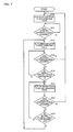
- FIG. 7 is a flowchart illustrating the flow of an operation state transition process that allows a transition in the operation state of the touch operation performed on the operation surface 39 .
- the operation state is set to the non-operation state (i.e., initial state) (step S 10 ).
- the step S 12 is performed again.
- the operation state is set to the first operation state (step S 14 ).
- the operation state is set to the non-operation state (step S 10 ).
- the moving distance i.e., the distance between the detected coordinates acquired at the current acquisition timing and the detected coordinates acquired at the preceding acquisition timing
- the step S 16 is performed again.
- the operation state is set to the second operation state (step S 20 ).
- the operation state is set to the non-operation state (step S 10 ).
- the moving distance i.e., the distance between the detected coordinates acquired at the current acquisition timing and the detected coordinates acquired at the preceding acquisition timing
- the operation state is set to the first operation state (step S 14 ).
- the step S 22 is performed again.
- FIG. 8 is a flowchart illustrating the flow of a correction process that calculates the corrected coordinates by correcting the detected coordinates.
- the detected coordinates are acquired every 1/60th of a second (acquisition timing) (step S 30 ).
- acquisition timing acquisition timing
- the detected coordinates in the first operation state acquired at the acquisition timing immediately before the operation state has transitioned to the second operation state are extracted from the detected coordinate storage section 622 (step S 34 ).
- the corrected coordinates are then calculated, one endpoint being indicated by the extracted detected coordinates in the first operation state, a midpoint being indicated by the detected coordinates acquired at the current acquisition timing, and the other endpoint being indicated by the corrected coordinates (step S 36 ).
- the detected coordinates are acquired at the next acquisition timing (step S 38 ).
- the step S 36 is performed again, and the corrected coordinates are calculated, one endpoint being indicated by the extracted detected coordinates in the first operation state, a midpoint being indicated by the detected coordinates stored at the current acquisition timing, and the other endpoint being indicated by the corrected coordinates (step S 36 ).
- the correction process is terminated.
- FIG. 9 is a flowchart illustrating a flow of a movement process that calculates the movement information about a moving object (ball 216 ) displayed on the screen.
- step S 52 When the operation state has transitioned to the non-operation state (the hold operation performed on the left area 204 illustrated in FIG. 5 has ended) (Y in step S 52 ), the count value of the first counter is stored (step S 54 ), and the count value of the third counter that counts the period in which the non-operation state is performed is updated (step S 56 ).
- the operation state has transitioned to the first operation state the slide operation has been performed on the right area 206 after the hold operation performed on the left area 204 illustrated in FIG.
- step S 58 the count value of the third counter is stored (step S 60 ), and the detected moving vector is calculated based on the detected coordinates at the first frame and the detected coordinates at the twelfth frame after the slide operation has started (step S 62 ). Specifically, the corrected coordinates are not used since the slide operation has been performed after the hold operation has ended.
- the movement information about the moving object is calculated based on the value of the first counter, the value of the third counter, and the detected moving vector (step S 63 ).
- the moving direction of the moving object is calculated so that the moving direction is more closely aligned with the vertical direction as the count value of the first counter increases (i.e., the hold operation is performed for a longer period), and the moving speed of the moving object is calculated so that the moving speed decreases as the count value of the third counter increases (i.e., the period between the hold operation and the slide operation increases). Therefore, it is necessary to reduce the period between the hold operation and the slide operation in order to increase the moving speed of the moving object.
- step S 64 When the count value of the third counter has reached a given value (e.g., a value corresponding to 3 seconds) (Y in step S 64 ) without the operation state transitioning to the first operation state (N in step S 58 ) after the count value of the third counter has been updated (step S 56 ) (i.e., the slide operation is not performed after 3 seconds has elapsed after the hold operation has ended), the hold operation (i.e., the preparatory operation of the player character 200 ) is canceled, and the step S 50 is performed again.
- a given value e.g., a value corresponding to 3 seconds
- step S 70 When the operation state has transitioned to the second operation state (the slide operation has been performed in a state in which the hold operation is performed on the left area 204 illustrated in FIG. 5 ) (Y in step S 70 ) without the operation state transitioning to the non-operation state in the step S 52 (N in step S 52 ), the count value of the first counter is stored (step S 72 ), and the corrected moving vector is calculated based on the corrected coordinates at the first frame and the corrected coordinates at the twelfth frame after the slide operation has started (step S 74 ). Specifically, the corrected coordinates are used since the slide operation has been performed in a state in which the hold operation is performed. The movement information about the moving object is then calculated based on the count value of the first counter and the corrected moving vector (step S 76 ).
- the player may perform the slide operation while performing the hold operation in order to increase the moving speed of the moving object by reducing the period between the hold operation and the slide operation as much as possible.
- the moving object can be moved corresponding to the touch position of the slide operation using the method according to this embodiment.
- the state determination section 106 determines the operation state is the first operation state when the detection value has been output from the second detection section 52 when the operation state is the non-operation state. Note that the state determination section 106 may determine that the operation state is the first operation state when the detected coordinates corresponding to the first area have been acquired.
- the distance d is set as the first threshold value of the moving amount of the detected coordinates in the first operation state
- the distance d/2 is set as the second threshold value of the moving amount of the detected coordinates in the second operation state.
- the first threshold value may be the same as the second threshold value, or the second threshold value may be larger than the first threshold value.
- the state determination section 106 determines the operation state based on the moving amount of the detected coordinates.
- a pulse overshoot
- the state determination section 106 may determine that the operation state has transitioned from the first operation state to the second operation state, and vice versa, based on occurrence of a pulse.
- the moving object is moved irrespective of whether the player has performed the slide operation after finishing the hold operation or performed the slide operation while performing the hold operation (see the example illustrated in FIG. 5 ).
- the moving object may not be moved when the player does not perform the slide operation while performing the hold operation (i.e., the touch operation in the second operation state).
- the moving object may be moved based on a state parameter of the player character or the type of player character.
- the moving amount, the moving direction, the moving speed, and the moving accuracy of the moving object may be changed based on a fatigue level parameter of the player character.
- the moving amount, the moving direction, the moving speed, and the moving accuracy of the moving object may be changed based on the type of club held by the player character.
- the display control section 114 may move the moving object based on the moving amount of the detected coordinates when the operation state is the first operation state without performing the conversion process on the moving amount of the detected coordinates, and may perform the conversion process on the moving amount of the detected coordinates when the operation state is the second operation state, and move the moving object based on the moving amount of the detected coordinates.
- the display control section 114 may move the moving object based on the moving amount of the detected coordinates when the operation state is the first operation state without performing the conversion process on the moving amount of the detected coordinates, and may perform the conversion process on the moving amount of the detected coordinates when the operation state is the second operation state, and move the moving object based on the moving amount of the detected coordinates.
- the moving direction of the detected coordinates is the same (parallel) as that when the player has performed the slide operation after finishing the hold operation, and the moving speed (moving amount) of the detected coordinates is half that when the player has performed the slide operation after finishing the hold operation. Therefore, the moving speed and the moving amount of the moving object may be calculated after doubling the moving speed (moving amount) of the detected coordinates. This makes it possible to move the moving object corresponding to the movement of the first position or the second position in the second operation state without calculating the corrected coordinates.
- the touch position has moved from R 1 in a state in which the tip of the left touch pen 41 comes in contact with the operation surface 39 while the touch position of the tip of the right touch pen 41 is maintained at the point R 1 when the midpoint has moved from the point P 2 to the point P 3 in the second operation state, and the coordinates of the point R 2 considered to be the touch position of the left touch pen 41 may be calculated, as illustrated in FIG. 10D .
- the correction section 108 may calculate the corrected coordinates when new detected coordinates have been acquired in the second operation state, one endpoint being indicated by the corrected coordinates initially calculated in the second operation state, a midpoint being indicated by the detected coordinates currently acquired in the second operation state, and the other endpoint being indicated by the corrected coordinates.
- the player performs the hold operation at the point P 1 in the left area of the first display screen 17 , performs the hold operation at the point R 1 in the right area, and then performs the slide operation from the point P 1 , for example, the coordinates of the point R 2 (i.e., the touch position of the slide operation) are calculated as the corrected coordinates.
- the above embodiments have been described taking an example executing a soccer PK game.
- the above method may also be applied to a ball sport game other than a soccer game, such as a baseball game or a golf game, and may also be applied to a sport game other than a ball sport game, such as a ski game or a swim game.
- FIGS. 11A to 11C are diagrams illustrating an example in which the game system 10 executes a swim game.
- a right arrow object 218 i.e., first area
- a left arrow object 220 i.e., second area
- the player is instructed (“Slide!”) to alternately perform the slide operation along the right arrow object 218 and the slide operation along the left arrow object 220 .
- An image in which the player character swims is displayed on the second display screen 33 (not illustrated).
- the moving speed and the moving direction of the player character are determined based on the timing, the speed, the moving path, and the balance of the slide operation performed along the right arrow object 218 and the slide operation performed along the left arrow object 220 .
- the movement of the touch position coincides with the movement of the detected coordinates since the operation state is the first operation state.
- the movement information about the player character is determined based on the moving speed and the moving path of the detected coordinates without calculating the corrected coordinates.
- the movement of the touch position does not coincide with the movement of the detected coordinates since the operation state is the second operation state.
- the corrected coordinates are calculated based on the touch position and the detected coordinates of the hold operation performed at the upper right position on the operation surface 39 , and the movement information about the player character is determined based on the moving speed and the moving path of the corrected coordinates.
- the movement of the touch position does not coincide with the movement of the detected coordinates since the operation state is the second operation state.
- the corrected coordinates are calculated based on the upper left position on the operation surface 39 and the detected coordinates, and the movement information about the player character is determined based on the moving speed and the moving path of the corrected coordinates.
- FIGS. 12A to 12E are diagrams illustrating an example a game executed by the game system 10 .
- a plurality of sheep characters 222 and a wolf character 224 that attacks the sheep characters 222 are displayed on the first display screen 17 (operation surface 39 ).
- the sheep characters 222 escape from the wolf character 224 , and the wolf character 224 runs after the sheep characters 222 .
- FIG. 12A when the player has performed the hold operation at the position at which the wolf character 224 is displayed, the movement of the wolf character 224 is stopped.
- FIG. 12B when the player has performed the slide operation at the position at which the sheep character 222 is displayed, the sheep character 222 is moved to a safe place.
- the coordinates of the touch position coincide with the detected coordinates since the operation state is the first operation state.
- whether or not the position of the detected coordinates coincides with the display position (i.e., given position) of the wolf character 224 is determined without calculating the corrected coordinates.
- the movement of the wolf character 224 is stopped when the position of the detected coordinates coincides with the display position of the wolf character 224 .
- the coordinates of the touch position coincide with the detected coordinates since the operation state is the first operation state.
- whether or not the moving path of the detected coordinates intersects (i.e., coincides with) the display position (i.e., given position) of the sheep character 222 is determined without calculating the corrected coordinates.
- the sheep character 222 is moved to a safe place when the moving path of the detected coordinates intersects the display position of the sheep character 222 .
- the corrected coordinates are calculated based on the detected coordinates and the touch position of the hold operation on the wolf character 224 , whether or not the moving path of the corrected coordinates intersects (i.e., coincides with) the display position (i.e., given position) of the sheep character 222 is determined.
- the sheep character 222 is moved to a safe place when the moving path of the corrected coordinates intersects the display position of the sheep character 222 .
- the movement of the wolf character 224 may be stopped.
- the hold operation i.e., first touch operation
- the hold operation i.e., second touch operation
- the movement of the sheep character 222 may be stopped.
- the operation state is the second operation state
- the coordinates of the touch position do not coincide with the detected coordinates.
- the corrected coordinates are calculated based on the detected coordinates and the touch position of the hold operation performed at the position at which the wolf character 224 is displayed, and whether or not the corrected coordinates coincide with the coordinates of the display position (i.e., given position) of the sheep character 222 is determined.
- the movement of the sheep character 222 may be stopped when the corrected coordinates coincide with the coordinates of the display position of the sheep character 222 .
- the touch position of the slide operation may be calculated as the corrected coordinates, and the wolf character 224 may be moved to follow the slide operation based on the corrected coordinates (see FIG. 10D ).
- the coordinates of the touch position do not coincide with the detected coordinates since the operation state is the second operation state.
- the corrected coordinates are calculated based on the detected coordinates and the touch position of the hold operation performed on the button 226 , and a curve 228 is drawn along the moving path of the corrected coordinates.
- a quiz may be displayed when the player performs the hold operation (i.e., first touch operation) using the left touch pen 41 at the lower left position of the first display screen 17 at which the button 226 (i.e., first area) is displayed, and the player may perform an answer operation by performing a touch operation on a circular button display 230 (i.e., second area) displayed at the upper right position of the first display screen 17 or a cross-shaped button display 232 (i.e., second area) displayed at the lower right position of the first display screen 17 .
- a circular button display 230 i.e., second area
- a cross-shaped button display 232 i.e., second area
- Whether or not the touch position of the touch operation coincides with the display position of the button corresponding to the correct answer may be determined, and a process (e.g., outputs sound that indicate a correct answer, or adds points) other than the display control process may be performed when the touch position of the touch Operation coincides with the display position of the button corresponding to the correct answer.
- a process e.g., outputs sound that indicate a correct answer, or adds points
- the corrected coordinates are calculated based on the detected coordinates and the touch position of the hold operation performed on the button 226 . Whether or not the corrected coordinates coincide with the coordinates of the display position of the circular button display 230 or the cross-shaped button display 232 is determined.
- Whether or not the moving path of the detected coordinates in the second operation state coincides with a given moving path may be determined. For example, an equilateral triangle and a square having an identical side length may be displayed on the first display screen 17 , and data that indicates the moving path of the midpoint when the player traces each side of the equilateral triangle with the tip of an arbitrary finger of the left hand, and traces each side of the square with the tip of an arbitrary finger of the right hand may be provided in advance. Whether or not the moving path of the detected coordinates in the second operation state coincides with such a moving path may be determined. In this case, the equilateral triangle and the square may be displayed side by side on the first display screen 17 to guide the player. The moving path may have a given width taking account of a difference in movement of the fingers.
Landscapes
- Engineering & Computer Science (AREA)
- General Engineering & Computer Science (AREA)
- Theoretical Computer Science (AREA)
- Human Computer Interaction (AREA)
- Physics & Mathematics (AREA)
- General Physics & Mathematics (AREA)
- User Interface Of Digital Computer (AREA)
- Processing Or Creating Images (AREA)
- Position Input By Displaying (AREA)
Abstract
Description
Claims (26)
Applications Claiming Priority (2)
| Application Number | Priority Date | Filing Date | Title |
|---|---|---|---|
| JP2009218083A JP5325060B2 (en) | 2009-09-18 | 2009-09-18 | Program, information storage medium and image control system |
| JP2009-218083 | 2009-09-18 |
Publications (2)
| Publication Number | Publication Date |
|---|---|
| US20110069040A1 US20110069040A1 (en) | 2011-03-24 |
| US9030448B2 true US9030448B2 (en) | 2015-05-12 |
Family
ID=43756227
Family Applications (1)
| Application Number | Title | Priority Date | Filing Date |
|---|---|---|---|
| US12/884,789 Expired - Fee Related US9030448B2 (en) | 2009-09-18 | 2010-09-17 | Information storage medium and image control system for multi-touch resistive touch panel display |
Country Status (2)
| Country | Link |
|---|---|
| US (1) | US9030448B2 (en) |
| JP (1) | JP5325060B2 (en) |
Families Citing this family (11)
| Publication number | Priority date | Publication date | Assignee | Title |
|---|---|---|---|---|
| US9223440B2 (en) * | 2011-06-28 | 2015-12-29 | Avago Technologies General Ip (Singapore) Pte. Ltd. | Optical navigation utilizing speed based algorithm selection |
| JP5738809B2 (en) * | 2012-07-31 | 2015-06-24 | 株式会社コナミデジタルエンタテインメント | GAME DEVICE, GAME DEVICE CONTROL METHOD, GAME SYSTEM, GAME SYSTEM CONTROL METHOD, AND PROGRAM |
| CN104704463A (en) * | 2012-10-05 | 2015-06-10 | 三菱电机株式会社 | Display device |
| JP6217004B2 (en) * | 2013-06-28 | 2017-10-25 | 株式会社コナミデジタルエンタテインメント | Movement control apparatus and program |
| JP6240580B2 (en) * | 2014-09-05 | 2017-11-29 | 株式会社スクウェア・エニックス | Game device |
| JP6097427B1 (en) * | 2016-02-29 | 2017-03-15 | 株式会社コロプラ | Game program |
| JP6805589B2 (en) * | 2016-07-11 | 2020-12-23 | 富士通株式会社 | Information processing equipment, information processing system, information processing program and information processing method |
| JP7012485B2 (en) * | 2016-12-27 | 2022-01-28 | 株式会社ワコム | Image information processing device and image information processing method |
| JP6593932B2 (en) * | 2017-10-16 | 2019-10-23 | 株式会社ソディック | Machine operation panel |
| KR102149105B1 (en) * | 2019-09-18 | 2020-08-27 | 세종대학교산학협력단 | Mixed reality based 3D sketching device and method |
| JP7051954B6 (en) * | 2020-08-25 | 2022-05-06 | グリー株式会社 | Programs, game control methods, and information processing equipment |
Citations (13)
| Publication number | Priority date | Publication date | Assignee | Title |
|---|---|---|---|---|
| JP2001134382A (en) | 1999-11-04 | 2001-05-18 | Sony Corp | Graphic processing unit |
| US20050046621A1 (en) * | 2003-08-29 | 2005-03-03 | Nokia Corporation | Method and device for recognizing a dual point user input on a touch based user input device |
| US20060025218A1 (en) * | 2004-07-29 | 2006-02-02 | Nintendo Co., Ltd. | Game apparatus utilizing touch panel and storage medium storing game program |
| US20060026536A1 (en) * | 2004-07-30 | 2006-02-02 | Apple Computer, Inc. | Gestures for touch sensitive input devices |
| JP2006136638A (en) | 2004-11-15 | 2006-06-01 | Nintendo Co Ltd | Game program |
| US20060139340A1 (en) * | 2001-10-03 | 2006-06-29 | 3M Innovative Properties Company | Touch panel system and method for distinguishing multiple touch inputs |
| US20090207140A1 (en) * | 2008-02-19 | 2009-08-20 | Sony Ericsson Mobile Communications Ab | Identifying and responding to multiple time-overlapping touches on a touch panel |
| US7708641B2 (en) * | 2004-01-20 | 2010-05-04 | Nintendo Co., Ltd. | Game program for touch control hand-held game device |
| US7907125B2 (en) * | 2007-01-05 | 2011-03-15 | Microsoft Corporation | Recognizing multiple input point gestures |
| US8345019B2 (en) * | 2009-02-20 | 2013-01-01 | Elo Touch Solutions, Inc. | Method and apparatus for two-finger touch coordinate recognition and rotation gesture recognition |
| US8445793B2 (en) * | 2008-12-08 | 2013-05-21 | Apple Inc. | Selective input signal rejection and modification |
| US8477107B2 (en) * | 2008-11-12 | 2013-07-02 | Htc Corporation | Function selection systems and methods |
| US8717323B2 (en) * | 2009-05-11 | 2014-05-06 | Adobe Systems Incorporated | Determining when a touch is processed as a mouse event |
-
2009
- 2009-09-18 JP JP2009218083A patent/JP5325060B2/en active Active
-
2010
- 2010-09-17 US US12/884,789 patent/US9030448B2/en not_active Expired - Fee Related
Patent Citations (15)
| Publication number | Priority date | Publication date | Assignee | Title |
|---|---|---|---|---|
| US6958749B1 (en) | 1999-11-04 | 2005-10-25 | Sony Corporation | Apparatus and method for manipulating a touch-sensitive display panel |
| JP2001134382A (en) | 1999-11-04 | 2001-05-18 | Sony Corp | Graphic processing unit |
| US20060139340A1 (en) * | 2001-10-03 | 2006-06-29 | 3M Innovative Properties Company | Touch panel system and method for distinguishing multiple touch inputs |
| US20050046621A1 (en) * | 2003-08-29 | 2005-03-03 | Nokia Corporation | Method and device for recognizing a dual point user input on a touch based user input device |
| US7708641B2 (en) * | 2004-01-20 | 2010-05-04 | Nintendo Co., Ltd. | Game program for touch control hand-held game device |
| US20060025218A1 (en) * | 2004-07-29 | 2006-02-02 | Nintendo Co., Ltd. | Game apparatus utilizing touch panel and storage medium storing game program |
| US20060026536A1 (en) * | 2004-07-30 | 2006-02-02 | Apple Computer, Inc. | Gestures for touch sensitive input devices |
| US8239784B2 (en) * | 2004-07-30 | 2012-08-07 | Apple Inc. | Mode-based graphical user interfaces for touch sensitive input devices |
| JP2006136638A (en) | 2004-11-15 | 2006-06-01 | Nintendo Co Ltd | Game program |
| US7907125B2 (en) * | 2007-01-05 | 2011-03-15 | Microsoft Corporation | Recognizing multiple input point gestures |
| US20090207140A1 (en) * | 2008-02-19 | 2009-08-20 | Sony Ericsson Mobile Communications Ab | Identifying and responding to multiple time-overlapping touches on a touch panel |
| US8477107B2 (en) * | 2008-11-12 | 2013-07-02 | Htc Corporation | Function selection systems and methods |
| US8445793B2 (en) * | 2008-12-08 | 2013-05-21 | Apple Inc. | Selective input signal rejection and modification |
| US8345019B2 (en) * | 2009-02-20 | 2013-01-01 | Elo Touch Solutions, Inc. | Method and apparatus for two-finger touch coordinate recognition and rotation gesture recognition |
| US8717323B2 (en) * | 2009-05-11 | 2014-05-06 | Adobe Systems Incorporated | Determining when a touch is processed as a mouse event |
Also Published As
| Publication number | Publication date |
|---|---|
| JP5325060B2 (en) | 2013-10-23 |
| JP2011065600A (en) | 2011-03-31 |
| US20110069040A1 (en) | 2011-03-24 |
Similar Documents
| Publication | Publication Date | Title |
|---|---|---|
| US9030448B2 (en) | Information storage medium and image control system for multi-touch resistive touch panel display | |
| JP5103538B2 (en) | GAME DEVICE, GAME CONTROL PROGRAM, AND GAME CONTROL METHOD | |
| US11253776B2 (en) | Computer device and evaluation control method | |
| US10576382B2 (en) | Golf game apparatus, storage medium, golf game system and golf game control method | |
| US20200038746A1 (en) | Game system, game control device, and information storage medium | |
| US20140248956A1 (en) | Game device, control method of game device, program, and information storage medium | |
| JP5248705B2 (en) | GAME DEVICE, GAME CONTROL PROGRAM, AND GAME CONTROL METHOD | |
| US7641551B2 (en) | Game program and game apparatus using input to pointing device | |
| US20130065687A1 (en) | Game Device, Game Control Method, and Game Control Program for Controlling Game on the Basis of a Position Input Received via Touch Panel | |
| US10099118B2 (en) | Interface for advancing game by touch input, and terminal | |
| JP4688473B2 (en) | PROGRAM, INFORMATION STORAGE MEDIUM, AND GAME DEVICE | |
| JP6207027B2 (en) | GAME DEVICE AND GAME CONTROL PROGRAM | |
| JP2010273891A (en) | GAME PROGRAM AND GAME DEVICE | |
| JP2016077438A (en) | Game program | |
| JP5526252B2 (en) | GAME DEVICE, GAME CONTROL PROGRAM, AND GAME CONTROL METHOD | |
| JP2016083050A (en) | Game program | |
| JP2017012619A (en) | A computer program that plays a game by touch operation | |
| JP6301813B2 (en) | GAME PROGRAM AND GAME DEVICE | |
| JP5771719B2 (en) | GAME DEVICE AND GAME CONTROL PROGRAM | |
| JP5652046B2 (en) | VIDEO GAME DEVICE, VIDEO GAME CONTROL METHOD, CONTROL PROGRAM, AND RECORDING MEDIUM | |
| JP2016083047A (en) | Game program | |
| JP2016083049A (en) | Game program | |
| JP6675053B2 (en) | Game device and game control program | |
| JP2016209228A (en) | Swing analysis device, swing analysis method, swing analysis program, and swing analysis system provided with swing analysis device | |
| JP6635487B2 (en) | Program, game control method and game device |
Legal Events
| Date | Code | Title | Description |
|---|---|---|---|
| AS | Assignment |
Owner name: NAMCO BANDAI GAMES INC., JAPAN Free format text: ASSIGNMENT OF ASSIGNORS INTEREST;ASSIGNORS:ITO, MAYA;SUZUI, MASANOBU;SIGNING DATES FROM 20101012 TO 20101014;REEL/FRAME:025198/0666 |
|
| AS | Assignment |
Owner name: BANDAI NAMCO GAMES INC., JAPAN Free format text: CHANGE OF NAME;ASSIGNOR:NAMCO BANDAI GAMES INC.;REEL/FRAME:032975/0393 Effective date: 20140401 |
|
| STCF | Information on status: patent grant |
Free format text: PATENTED CASE |
|
| FEPP | Fee payment procedure |
Free format text: PAYOR NUMBER ASSIGNED (ORIGINAL EVENT CODE: ASPN); ENTITY STATUS OF PATENT OWNER: LARGE ENTITY |
|
| AS | Assignment |
Owner name: BANDAI NAMCO ENTERTAINMENT INC., JAPAN Free format text: CHANGE OF NAME;ASSIGNOR:BANDAI NAMCO GAMES INC.;REEL/FRAME:038104/0788 Effective date: 20150401 |
|
| MAFP | Maintenance fee payment |
Free format text: PAYMENT OF MAINTENANCE FEE, 4TH YEAR, LARGE ENTITY (ORIGINAL EVENT CODE: M1551); ENTITY STATUS OF PATENT OWNER: LARGE ENTITY Year of fee payment: 4 |
|
| FEPP | Fee payment procedure |
Free format text: MAINTENANCE FEE REMINDER MAILED (ORIGINAL EVENT CODE: REM.); ENTITY STATUS OF PATENT OWNER: LARGE ENTITY |
|
| LAPS | Lapse for failure to pay maintenance fees |
Free format text: PATENT EXPIRED FOR FAILURE TO PAY MAINTENANCE FEES (ORIGINAL EVENT CODE: EXP.); ENTITY STATUS OF PATENT OWNER: LARGE ENTITY |
|
| STCH | Information on status: patent discontinuation |
Free format text: PATENT EXPIRED DUE TO NONPAYMENT OF MAINTENANCE FEES UNDER 37 CFR 1.362 |
|
| FP | Lapsed due to failure to pay maintenance fee |
Effective date: 20230512 |