US9019328B2 - Organic compound, organic light-emitting device, and display apparatus - Google Patents
Organic compound, organic light-emitting device, and display apparatus Download PDFInfo
- Publication number
- US9019328B2 US9019328B2 US14/346,291 US201214346291A US9019328B2 US 9019328 B2 US9019328 B2 US 9019328B2 US 201214346291 A US201214346291 A US 201214346291A US 9019328 B2 US9019328 B2 US 9019328B2
- Authority
- US
- United States
- Prior art keywords
- light
- compound
- groups
- organic
- substituted
- Prior art date
- Legal status (The legal status is an assumption and is not a legal conclusion. Google has not performed a legal analysis and makes no representation as to the accuracy of the status listed.)
- Active
Links
- PLXIVKCMZMVMJI-UHFFFAOYSA-N C1=CC=C(C2=C3C=C4C(=CC3=C(C3=CC=CC=C3)C3=C2C2=CC=CC5=CC=CC3=C52)C2=C3C5=C(C=C2)C2=C(C(C6=CC=CC=C6)=C6C=CC=CC6=C2C2=CC=CC=C2)/C5=C/C=C/43)C=C1 Chemical compound C1=CC=C(C2=C3C=C4C(=CC3=C(C3=CC=CC=C3)C3=C2C2=CC=CC5=CC=CC3=C52)C2=C3C5=C(C=C2)C2=C(C(C6=CC=CC=C6)=C6C=CC=CC6=C2C2=CC=CC=C2)/C5=C/C=C/43)C=C1 PLXIVKCMZMVMJI-UHFFFAOYSA-N 0.000 description 3
- 0 [1*]C1=C([20*])C2=C([19*])C3=C(C([4*])=C2C([3*])=C1[2*])C1=C2C4=C(C([6*])=C1[5*])C1=C([7*])C5=C([8*])C6=C(C([15*])=C5C([16*])=C1/C4=C([17*])/C([18*])=C/32)C1=C([14*])C([13*])=C([12*])C2=C([11*])C([10*])=C([9*])C6=C21 Chemical compound [1*]C1=C([20*])C2=C([19*])C3=C(C([4*])=C2C([3*])=C1[2*])C1=C2C4=C(C([6*])=C1[5*])C1=C([7*])C5=C([8*])C6=C(C([15*])=C5C([16*])=C1/C4=C([17*])/C([18*])=C/32)C1=C([14*])C([13*])=C([12*])C2=C([11*])C([10*])=C([9*])C6=C21 0.000 description 3
- VIZUPBYFLORCRA-UHFFFAOYSA-N C1=CC2=C(C=C1)C=C(C1=C3C=CC=CC3=C(C3=CC=C4/C=C\C=C/C4=C3)C3=C1C=CC=C3)C=C2 Chemical compound C1=CC2=C(C=C1)C=C(C1=C3C=CC=CC3=C(C3=CC=C4/C=C\C=C/C4=C3)C3=C1C=CC=C3)C=C2 VIZUPBYFLORCRA-UHFFFAOYSA-N 0.000 description 2
- LSEVINOJNQFWNK-UHFFFAOYSA-N C1=CC2=CC3=C(C=C2C=C1)/C1=C/C=C2/C4=CC5=C(C=C4C4=CC=C3C1=C42)C1=CC=CC2=C1C5=CC=C2 Chemical compound C1=CC2=CC3=C(C=C2C=C1)/C1=C/C=C2/C4=CC5=C(C=C4C4=CC=C3C1=C42)C1=CC=CC2=C1C5=CC=C2 LSEVINOJNQFWNK-UHFFFAOYSA-N 0.000 description 2
- LTPTURSKADNYLT-UHFFFAOYSA-N C1=CC2=CC=C3C=CC(C4=CC5=C(C=C4)C=C(/C4=C/C=C6/C=C/C7=C/C=C\C8=CC=C4C6=C87)C=C5)=C4/C=C\C(=C1)C2=C34 Chemical compound C1=CC2=CC=C3C=CC(C4=CC5=C(C=C4)C=C(/C4=C/C=C6/C=C/C7=C/C=C\C8=CC=C4C6=C87)C=C5)=C4/C=C\C(=C1)C2=C34 LTPTURSKADNYLT-UHFFFAOYSA-N 0.000 description 2
- CLIZJDQRRAYQAH-UHFFFAOYSA-N C1=CC=C(C2=C3C=CC=CC3=C(C3=CC=CC=C3)C3=C2C=C2C(=C3)C3=CC=CC4=C3C2=CC=C4)C=C1 Chemical compound C1=CC=C(C2=C3C=CC=CC3=C(C3=CC=CC=C3)C3=C2C=C2C(=C3)C3=CC=CC4=C3C2=CC=C4)C=C1 CLIZJDQRRAYQAH-UHFFFAOYSA-N 0.000 description 2
- QDPYKHNNVLLLBY-UHFFFAOYSA-N CC(C)(C)C1=C/C2=CC=C3C4=C2\C(=C/1)C=C/C4=C/C=C\3C1=CC2=C(C=C1)C=C(C1=CC=C3C=CC=CC3=C1)C=C2 Chemical compound CC(C)(C)C1=C/C2=CC=C3C4=C2\C(=C/1)C=C/C4=C/C=C\3C1=CC2=C(C=C1)C=C(C1=CC=C3C=CC=CC3=C1)C=C2 QDPYKHNNVLLLBY-UHFFFAOYSA-N 0.000 description 2
- RHBIHFYSUHWHIY-UHFFFAOYSA-N CC1(C)OB(C2=C3\C=CC=C4C5=C(C(=C43)\C=C/2)C(C2=CC=CC=C2C2=CC=CC=C2)=C2/C=C3/C4=C6C(=CC=C/C6=C/C=C\4)/C3=C/C2=C5C2=C(C3=CC=CC=C3)C=CC=C2)OC1(C)C Chemical compound CC1(C)OB(C2=C3\C=CC=C4C5=C(C(=C43)\C=C/2)C(C2=CC=CC=C2C2=CC=CC=C2)=C2/C=C3/C4=C6C(=CC=C/C6=C/C=C\4)/C3=C/C2=C5C2=C(C3=CC=CC=C3)C=CC=C2)OC1(C)C RHBIHFYSUHWHIY-UHFFFAOYSA-N 0.000 description 2
- GIEPWBVZJFKFAI-UHFFFAOYSA-N BrC1=C(C2=C3/C=C\C=C4/C3=C(C=C2)C2=C(C3=CC=CC=C3)C3=CC5=C(C=C3C(C3=CC=CC=C3)=C24)/C2=C/C=C\C3=CC=CC5=C32)C=C2C=CC=CC2=C1.BrC1=CC2=C(C=CC=C2)C=C1Br.C.C1=CC=C(C2=C3C4=C5C6=C(C=C4)C4=C(C=C7C=CC=CC7=C4)/C6=C/C=C\5C3=C(C3=CC=CC=C3)C3=CC4=C(C=C32)C2=C3C(=CC=C2)/C=C\C=C\43)C=C1.CC1(C)OBr(C2=C3/C=C\C=C4/C3=C(C=C2)C2=C(C3=CC=CC=C3)C3=CC5=C(C=C3C(C3=CC=CC=C3)=C24)/C2=C/C=C\C3=CC=CC5=C32)OC1(C)C Chemical compound BrC1=C(C2=C3/C=C\C=C4/C3=C(C=C2)C2=C(C3=CC=CC=C3)C3=CC5=C(C=C3C(C3=CC=CC=C3)=C24)/C2=C/C=C\C3=CC=CC5=C32)C=C2C=CC=CC2=C1.BrC1=CC2=C(C=CC=C2)C=C1Br.C.C1=CC=C(C2=C3C4=C5C6=C(C=C4)C4=C(C=C7C=CC=CC7=C4)/C6=C/C=C\5C3=C(C3=CC=CC=C3)C3=CC4=C(C=C32)C2=C3C(=CC=C2)/C=C\C=C\43)C=C1.CC1(C)OBr(C2=C3/C=C\C=C4/C3=C(C=C2)C2=C(C3=CC=CC=C3)C3=CC5=C(C=C3C(C3=CC=CC=C3)=C24)/C2=C/C=C\C3=CC=CC5=C32)OC1(C)C GIEPWBVZJFKFAI-UHFFFAOYSA-N 0.000 description 1
- BIXHKJDALMZJLL-LAYITYSASA-N BrC1=C(C2=C3\C=CC=C4C5=C(C6=CC=CC=C6)C6=C/C7=C(\C=C/6C(C6=CC=CC=C6)=C5C(=C43)\C=C/2)C2=C3C7=CC=C/C3=C/C=C\2)C=C2C=CC=CC2=C1.BrC1=C/C2=C(C=CC=C2)/C=C\1Br.C.C1=CC=C(C2=C3C4=CC=C5C6=C(/C=C7/C=CC=C/C7=C/6)C6=C5C4=C(/C=C\6)C3=C(C3=CC=CC=C3)/C3=C/C4=C(\C=C/23)C2=CC=C/C3=C/C=C\C4=C23)C=C1.CC1(C)OB(C2=C3\C=CC=C4C5=C(C6=CC=CC=C6)C6=C/C7=C(\C=C/6C(C6=CC=CC=C6)=C5C(=C43)\C=C/2)C2=C3C7=CC=C/C3=C/C=C\2)OC1(C)C.[2HH].[2H][2H].[2H][2H].[2H][2H].[2H][2H].[2H][2H].[2H][2H].[2H][2H] Chemical compound BrC1=C(C2=C3\C=CC=C4C5=C(C6=CC=CC=C6)C6=C/C7=C(\C=C/6C(C6=CC=CC=C6)=C5C(=C43)\C=C/2)C2=C3C7=CC=C/C3=C/C=C\2)C=C2C=CC=CC2=C1.BrC1=C/C2=C(C=CC=C2)/C=C\1Br.C.C1=CC=C(C2=C3C4=CC=C5C6=C(/C=C7/C=CC=C/C7=C/6)C6=C5C4=C(/C=C\6)C3=C(C3=CC=CC=C3)/C3=C/C4=C(\C=C/23)C2=CC=C/C3=C/C=C\C4=C23)C=C1.CC1(C)OB(C2=C3\C=CC=C4C5=C(C6=CC=CC=C6)C6=C/C7=C(\C=C/6C(C6=CC=CC=C6)=C5C(=C43)\C=C/2)C2=C3C7=CC=C/C3=C/C=C\2)OC1(C)C.[2HH].[2H][2H].[2H][2H].[2H][2H].[2H][2H].[2H][2H].[2H][2H].[2H][2H] BIXHKJDALMZJLL-LAYITYSASA-N 0.000 description 1
- QIAGORHEVMZLSU-UHFFFAOYSA-N C.C.C.C.C.C1=CC=C(/C2=C3\C=CC=C\C3=C(/C3=CC=CC=C3)C3=C2C2=CC=C4C5=CC6=C(\C7=CC=CC=C7)C7=C(C8=C9C7=CC=C/C9=C/C=C\8)/C(C7=CC=CC=C7)=C\6C=C5C5=C4C2=C3/C=C\5)C=C1.CC1(C)OB(C2=C3C=CC=C4C3=C(C=C2)C2=C4/C(C3=CC=CC=C3)=C3\C=CC=C\C3=C\2C2=CC=CC=C2)OC1(C)C.ClC1=CC2=C(C3=CC=CC=C3)\C3=C(C4=C5C(=CC=C4)C=CC=C53)/C(C3=CC=CC=C3)=C\2C=C1Br.ClC1=CC2=C(\C3=CC=CC=C3)C3=C(C4=C5C3=CC=C/C5=C/C=C\4)/C(C3=CC=CC=C3)=C\2C=C1C1=C2\C=CC=C3C4=C(C(=C32)\C=C/1)C(C1=CC=CC=C1)=C1C=CC=CC1=C4C1=CC=CC=C1.NC1=CC(Cl)=C(Br)C=C1C(=O)O.O=C1C(C2=CC=CC=C2)=C2C3=CC=C/C4=C/C=C\C(=C34)C2=C1C1=CC=CC=C1 Chemical compound C.C.C.C.C.C1=CC=C(/C2=C3\C=CC=C\C3=C(/C3=CC=CC=C3)C3=C2C2=CC=C4C5=CC6=C(\C7=CC=CC=C7)C7=C(C8=C9C7=CC=C/C9=C/C=C\8)/C(C7=CC=CC=C7)=C\6C=C5C5=C4C2=C3/C=C\5)C=C1.CC1(C)OB(C2=C3C=CC=C4C3=C(C=C2)C2=C4/C(C3=CC=CC=C3)=C3\C=CC=C\C3=C\2C2=CC=CC=C2)OC1(C)C.ClC1=CC2=C(C3=CC=CC=C3)\C3=C(C4=C5C(=CC=C4)C=CC=C53)/C(C3=CC=CC=C3)=C\2C=C1Br.ClC1=CC2=C(\C3=CC=CC=C3)C3=C(C4=C5C3=CC=C/C5=C/C=C\4)/C(C3=CC=CC=C3)=C\2C=C1C1=C2\C=CC=C3C4=C(C(=C32)\C=C/1)C(C1=CC=CC=C1)=C1C=CC=CC1=C4C1=CC=CC=C1.NC1=CC(Cl)=C(Br)C=C1C(=O)O.O=C1C(C2=CC=CC=C2)=C2C3=CC=C/C4=C/C=C\C(=C34)C2=C1C1=CC=CC=C1 QIAGORHEVMZLSU-UHFFFAOYSA-N 0.000 description 1
- LJQYCGVCLRCVOQ-UHFFFAOYSA-N C.C.CC(C)(C)C1=CC(C2=C3C4=CC=CC5=CC=CC(=C54)C3=C(C3=CC(C(C)(C)C)=CC(C(C)(C)C)=C3)C2=O)=CC(C(C)(C)C)=C1.CC(C)(C)C1=CC(C2=C3C=CC=CC3=C(C3=CC(C(C)(C)C)=CC(C(C)(C)C)=C3)C3=C2C2=CC=CC4=C(B5OC(C)(C)C(C)(C)O5)C=CC3=C24)=CC(C(C)(C)C)=C1 Chemical compound C.C.CC(C)(C)C1=CC(C2=C3C4=CC=CC5=CC=CC(=C54)C3=C(C3=CC(C(C)(C)C)=CC(C(C)(C)C)=C3)C2=O)=CC(C(C)(C)C)=C1.CC(C)(C)C1=CC(C2=C3C=CC=CC3=C(C3=CC(C(C)(C)C)=CC(C(C)(C)C)=C3)C3=C2C2=CC=CC4=C(B5OC(C)(C)C(C)(C)O5)C=CC3=C24)=CC(C(C)(C)C)=C1 LJQYCGVCLRCVOQ-UHFFFAOYSA-N 0.000 description 1
- BDYNVQNSUSPWFD-UHFFFAOYSA-N C.C.CC(C)(C)C1=CC(C2=C3C=C4C(=CC3=C(C3=CC(C(C)(C)C)=CC(C(C)(C)C)=C3)C3=C2C2=CC=CC5=C(B6OC(C)(C)C(C)(C)O6)C=CC3=C25)C2=C3C(=CC=C2)C=CC=C43)=CC(C(C)(C)C)=C1 Chemical compound C.C.CC(C)(C)C1=CC(C2=C3C=C4C(=CC3=C(C3=CC(C(C)(C)C)=CC(C(C)(C)C)=C3)C3=C2C2=CC=CC5=C(B6OC(C)(C)C(C)(C)O6)C=CC3=C25)C2=C3C(=CC=C2)C=CC=C43)=CC(C(C)(C)C)=C1 BDYNVQNSUSPWFD-UHFFFAOYSA-N 0.000 description 1
- NZQVICBTDXXDOC-UHFFFAOYSA-N C.C.CC(C)(C)C1=CC(C2=C3C=CC=CC3=C(C3=CC(C(C)(C)C)=CC(C(C)(C)C)=C3)C3=C2C2=CC=CC4=C(B5OC(C)(C)C(C)(C)O5)C=CC3=C24)=CC(C(C)(C)C)=C1.CC(C)(C)C1=CC2=CC(C(C)(C)C)=CC3=C2C(=C1)C1=C(C2=CC=CC=C2)C(=O)C(C2=CC=CC=C2)=C31 Chemical compound C.C.CC(C)(C)C1=CC(C2=C3C=CC=CC3=C(C3=CC(C(C)(C)C)=CC(C(C)(C)C)=C3)C3=C2C2=CC=CC4=C(B5OC(C)(C)C(C)(C)O5)C=CC3=C24)=CC(C(C)(C)C)=C1.CC(C)(C)C1=CC2=CC(C(C)(C)C)=CC3=C2C(=C1)C1=C(C2=CC=CC=C2)C(=O)C(C2=CC=CC=C2)=C31 NZQVICBTDXXDOC-UHFFFAOYSA-N 0.000 description 1
- LKBIVBPEZBQCEH-UHFFFAOYSA-N C.C.CC(C)(C)C1=CC2=C(C3=CC=CC=C3)C3=C(C4=CC=CC5=C(B6OC(C)(C)C(C)(C)O6)C=CC3=C45)C(C3=CC=CC=C3)=C2C=C1.CC(C)(C)C1=CC2=CC(C(C)(C)C)=CC3=C2C(=C1)C1=C(C2=CC=CC=C2)C(=O)C(C2=CC=CC=C2)=C31 Chemical compound C.C.CC(C)(C)C1=CC2=C(C3=CC=CC=C3)C3=C(C4=CC=CC5=C(B6OC(C)(C)C(C)(C)O6)C=CC3=C45)C(C3=CC=CC=C3)=C2C=C1.CC(C)(C)C1=CC2=CC(C(C)(C)C)=CC3=C2C(=C1)C1=C(C2=CC=CC=C2)C(=O)C(C2=CC=CC=C2)=C31 LKBIVBPEZBQCEH-UHFFFAOYSA-N 0.000 description 1
- DEPWAMKKRYONMA-UHFFFAOYSA-N C.C.CC(C)C1=C2C3=CC=CC4=CC=CC(=C43)C2=C(C(C)C)C1=O.CC(C)C1=C2C=CC=CC2=C(C(C)C)C2=C1C1=CC=CC3=C(B4OC(C)(C)C(C)(C)O4)C=CC2=C13 Chemical compound C.C.CC(C)C1=C2C3=CC=CC4=CC=CC(=C43)C2=C(C(C)C)C1=O.CC(C)C1=C2C=CC=CC2=C(C(C)C)C2=C1C1=CC=CC3=C(B4OC(C)(C)C(C)(C)O4)C=CC2=C13 DEPWAMKKRYONMA-UHFFFAOYSA-N 0.000 description 1
- NCDXAZXCQBWDAT-UHFFFAOYSA-N C.C.CC(C)C1=CC2=C3C(=C1B1OC(C)(C)C(C)(C)O1)C=CC(C(C)C)=C3C1=C2C=C2C(=C1)C(C(C)C)=C1C3=CC=CC4=CC=CC(=C43)C1=C2C(C)C Chemical compound C.C.CC(C)C1=CC2=C3C(=C1B1OC(C)(C)C(C)(C)O1)C=CC(C(C)C)=C3C1=C2C=C2C(=C1)C(C(C)C)=C1C3=CC=CC4=CC=CC(=C43)C1=C2C(C)C NCDXAZXCQBWDAT-UHFFFAOYSA-N 0.000 description 1
- NJCLXGTXWRXWAB-JJTKNYLSSA-N C.C1=CC=C(/C2=C3\C=CC=C\C3=C(/C3=CC=CC=C3)C3=C2C2=CC=C4C5=CC6=C(\C7=CC=CC=C7)C7=C(C8=C9C7=CC=C/C9=C/C=C\8)/C(C7=CC=CC=C7)=C\6C=C5C5=C4C2=C3/C=C\5)C=C1.CC1(C)OB(C2=C3C=CC=C4C3=C(C=C2)C2=C4/C(C3=CC=CC=C3)=C3\C=CC=C\C3=C\2C2=CC=CC=C2)OC1(C)C.ClC1=CC2=C(\C3=CC=CC=C3)C3=C(C4=C5C3=CC=C/C5=C/C=C\4)/C(C3=CC=CC=C3)=C\2C=C1Br.ClC1=CC2=C(\C3=CC=CC=C3)C3=C(C4=C5C3=CC=C/C5=C/C=C\4)/C(C3=CC=CC=C3)=C\2C=C1C1=C2\C=CC=C3C4=C(C(=C32)\C=C/1)C(C1=CC=CC=C1)=C1C=CC=CC1=C4C1=CC=CC=C1.[2HH].[2HH].[2H][2H].[2H][2H] Chemical compound C.C1=CC=C(/C2=C3\C=CC=C\C3=C(/C3=CC=CC=C3)C3=C2C2=CC=C4C5=CC6=C(\C7=CC=CC=C7)C7=C(C8=C9C7=CC=C/C9=C/C=C\8)/C(C7=CC=CC=C7)=C\6C=C5C5=C4C2=C3/C=C\5)C=C1.CC1(C)OB(C2=C3C=CC=C4C3=C(C=C2)C2=C4/C(C3=CC=CC=C3)=C3\C=CC=C\C3=C\2C2=CC=CC=C2)OC1(C)C.ClC1=CC2=C(\C3=CC=CC=C3)C3=C(C4=C5C3=CC=C/C5=C/C=C\4)/C(C3=CC=CC=C3)=C\2C=C1Br.ClC1=CC2=C(\C3=CC=CC=C3)C3=C(C4=C5C3=CC=C/C5=C/C=C\4)/C(C3=CC=CC=C3)=C\2C=C1C1=C2\C=CC=C3C4=C(C(=C32)\C=C/1)C(C1=CC=CC=C1)=C1C=CC=CC1=C4C1=CC=CC=C1.[2HH].[2HH].[2H][2H].[2H][2H] NJCLXGTXWRXWAB-JJTKNYLSSA-N 0.000 description 1
- PWCGGCVTLWFJET-UHFFFAOYSA-N C.CC(C)C1=CC2=C3C(=C1B1OC(C)(C)C(C)(C)O1)C=CC(C(C)C)=C3C1=C2C=C2C(=C1)C(C1=CC(C(C)(C)C)=CC(C(C)(C)C)=C1)=C1C3=CC=CC4=CC=CC(=C43)C1=C2C1=CC(C(C)(C)C)=CC(C(C)(C)C)=C1 Chemical compound C.CC(C)C1=CC2=C3C(=C1B1OC(C)(C)C(C)(C)O1)C=CC(C(C)C)=C3C1=C2C=C2C(=C1)C(C1=CC(C(C)(C)C)=CC(C(C)(C)C)=C1)=C1C3=CC=CC4=CC=CC(=C43)C1=C2C1=CC(C(C)(C)C)=CC(C(C)(C)C)=C1 PWCGGCVTLWFJET-UHFFFAOYSA-N 0.000 description 1
- DKAWNFVLANSFJQ-UHFFFAOYSA-N C.CCCCCCCCC1=C2C3=CC=CC4=CC=CC(=C43)C2=C(CCCCCCCC)C2=CC3=C(C=C21)C1=CC=CC2=C(B4OC(C)(C)C(C)(C)O4)C=CC3=C12 Chemical compound C.CCCCCCCCC1=C2C3=CC=CC4=CC=CC(=C43)C2=C(CCCCCCCC)C2=CC3=C(C=C21)C1=CC=CC2=C(B4OC(C)(C)C(C)(C)O4)C=CC3=C12 DKAWNFVLANSFJQ-UHFFFAOYSA-N 0.000 description 1
- QSPBDDXTIJKRCK-UHFFFAOYSA-N C.O=C1C(C2=CC(F)=CC(F)=C2)=C2C3=C4C(=CC=C3)/C=C\C=C/4C2=C1C1=CC(F)=CC(F)=C1 Chemical compound C.O=C1C(C2=CC(F)=CC(F)=C2)=C2C3=C4C(=CC=C3)/C=C\C=C/4C2=C1C1=CC(F)=CC(F)=C1 QSPBDDXTIJKRCK-UHFFFAOYSA-N 0.000 description 1
- QVKYXESFEJTUCY-UHFFFAOYSA-N C/C1=C2\C3=C/C(C(C)C)=C\C4=C\3C(=C(C(C)C)C=C4)\C2=C(/C)C2=C1C=C1C(=C2)C2=CC(C(C)C)=C3C4=C2/C1=C(C(C)C)\C=C4\C1=C\C2=C(C=CC=C2)\C=C/31.C1=CC=C(C2=C3C4=CC=C5C6=C4/C(=C\C=C6\C4=C\C6=C(C=CC=C6)\C=C/54)C3=C(C3=CC=CC=C3)C3=C2/C(C2=CC=CC=C2)=C2/C4=CC=CC5=C4C(=C\C=C/5)/C2=C/3C2=CC=CC=C2)C=C1.CC(C)/C1=C2\C3=CC=C4C5=CC6=C(C=C5/C5=C/C=C(C3=C45)/C2=C(\C(C)C)C2=C1C=CC(C(C)(C)C)=C2)/C(C(C)C)=C1\C(=C/6C(C)C)\C2=CC=CC3=C2\C1=C/C=C\3.CC(C)/C1=C2\C3=CC=C4C5=CC6=C(C=C5/C5=C/C=C(C3=C45)/C2=C(\C(C)C)C2=C1C=CC=C2)/C(C1=C2C=CC=CC2=C2C=CC=CC2=C1)=C1\C(=C/6C2=CC3=C(C=CC=C3)C3=C2C=CC=C3)\C2=CC=CC3=C2\C1=C/C=C\3.CC(C)/C1=C2\C3=CC=C4C5=CC6=C(C=C5/C5=C/C=C(C3=C45)/C2=C(\C(C)C)C2=C1C=CC=C2)/C(C1=CC(C(C)(C)C)=CC(C(C)(C)C)=C1)=C1\C(=C/6C2=CC(C(C)(C)C)=CC(C(C)(C)C)=C2)\C2=CC=CC3=C2\C1=C/C=C\3.CC(C)C1=C2C3=C4C(=C1)C1=C(C5=CC(C(C)(C)C)=CC(C(C)(C)C)=C5)C5=C(/C=C6/C7=C/C(C(C)(C)C)=C\C8=C/7C(=CC(C(C)(C)C)=C8)/C6=C/5)C(C5=CC(C(C)(C)C)=CC(C(C)(C)C)=C5)=C1/C4=C/C(C(C)C)=C3/C1=C/C3=C(C=CC=C3)/C=C\21.CC(C)C1=C2C3=C4C(=C1)C1=C(C5=CC(C(C)(C)C)=CC(C(C)(C)C)=C5)C5=C(/C=C6/C7=C/C=C\C8=C/7C(=CC=C8)/C6=C/5)C(C5=CC(C(C)(C)C)=CC(C(C)(C)C)=C5)=C1/C4=C/C(C(C)C)=C3/C1=C/C3=C(C=CC=C3)/C=C\21.CC(C)C1=C2C3=CC4=C(C=C3/C3=C/C(C(C)C)=C5C(=C23)C(=C1)/C1=C/C2=C(C=CC=C2)\C=C\51)/C(C(C)C)=C1\C(=C/4C(C)C)\C2=CC=CC3=C2\C1=C/C=C\3 Chemical compound C/C1=C2\C3=C/C(C(C)C)=C\C4=C\3C(=C(C(C)C)C=C4)\C2=C(/C)C2=C1C=C1C(=C2)C2=CC(C(C)C)=C3C4=C2/C1=C(C(C)C)\C=C4\C1=C\C2=C(C=CC=C2)\C=C/31.C1=CC=C(C2=C3C4=CC=C5C6=C4/C(=C\C=C6\C4=C\C6=C(C=CC=C6)\C=C/54)C3=C(C3=CC=CC=C3)C3=C2/C(C2=CC=CC=C2)=C2/C4=CC=CC5=C4C(=C\C=C/5)/C2=C/3C2=CC=CC=C2)C=C1.CC(C)/C1=C2\C3=CC=C4C5=CC6=C(C=C5/C5=C/C=C(C3=C45)/C2=C(\C(C)C)C2=C1C=CC(C(C)(C)C)=C2)/C(C(C)C)=C1\C(=C/6C(C)C)\C2=CC=CC3=C2\C1=C/C=C\3.CC(C)/C1=C2\C3=CC=C4C5=CC6=C(C=C5/C5=C/C=C(C3=C45)/C2=C(\C(C)C)C2=C1C=CC=C2)/C(C1=C2C=CC=CC2=C2C=CC=CC2=C1)=C1\C(=C/6C2=CC3=C(C=CC=C3)C3=C2C=CC=C3)\C2=CC=CC3=C2\C1=C/C=C\3.CC(C)/C1=C2\C3=CC=C4C5=CC6=C(C=C5/C5=C/C=C(C3=C45)/C2=C(\C(C)C)C2=C1C=CC=C2)/C(C1=CC(C(C)(C)C)=CC(C(C)(C)C)=C1)=C1\C(=C/6C2=CC(C(C)(C)C)=CC(C(C)(C)C)=C2)\C2=CC=CC3=C2\C1=C/C=C\3.CC(C)C1=C2C3=C4C(=C1)C1=C(C5=CC(C(C)(C)C)=CC(C(C)(C)C)=C5)C5=C(/C=C6/C7=C/C(C(C)(C)C)=C\C8=C/7C(=CC(C(C)(C)C)=C8)/C6=C/5)C(C5=CC(C(C)(C)C)=CC(C(C)(C)C)=C5)=C1/C4=C/C(C(C)C)=C3/C1=C/C3=C(C=CC=C3)/C=C\21.CC(C)C1=C2C3=C4C(=C1)C1=C(C5=CC(C(C)(C)C)=CC(C(C)(C)C)=C5)C5=C(/C=C6/C7=C/C=C\C8=C/7C(=CC=C8)/C6=C/5)C(C5=CC(C(C)(C)C)=CC(C(C)(C)C)=C5)=C1/C4=C/C(C(C)C)=C3/C1=C/C3=C(C=CC=C3)/C=C\21.CC(C)C1=C2C3=CC4=C(C=C3/C3=C/C(C(C)C)=C5C(=C23)C(=C1)/C1=C/C2=C(C=CC=C2)\C=C\51)/C(C(C)C)=C1\C(=C/4C(C)C)\C2=CC=CC3=C2\C1=C/C=C\3 QVKYXESFEJTUCY-UHFFFAOYSA-N 0.000 description 1
- IUBBKBRLSPJIEH-UHFFFAOYSA-N C/C1=C2\C3=CC=C(SC4=CC=CC=C4)C4=C3C(=C\C=C/4)/C2=C(\C)C2=C1C=C1C3=CC=C4C5=C3/C(=C\C=C5\C3=C(/C(C)C)C5=C(C=CC=C5)\C(C5=CC=CC=C5)=C/43)C1=C2.C1=CC=C(/C2=C3\C4=CC=C5C6=CC7=C(C=C6/C6=C/C=C(C4=C56)/C3=C(\C3=CC=CC=C3)C3=C2C=CC=C3)/C(C2CCCCC2)=C2\C(=C/7C3CCCCC3)\C3=CC=CC4=C3\C2=C/C=C\4)C=C1.C1=CC=C(/C2=C3\C4=C\C=C/C5=C\4C(=CC=C5)\C3=C(/C3=NC=CC=C3)C3=C2C=C2C(=C3)C3=CC=C4C5=C3/C2=C\C=C5\C2=C(/C3=CC=CC=N3)C3=C(C=CC=C3)\C(C3=NC=CC=C3)=C/42)N=C1.CC(C)/C1=C2\C3=CC=C4C5=CC6=C(C=C5/C5=C/C=C(C3=C45)/C2=C(\C(C)C)C2=C1C=CC=C2)/C(C1=CC=C(C#N)C=C1)=C1\C(=C/6C2=CC=C(C#N)C=C2)\C2=CC=CC3=C2\C1=C/C=C\3.CCCCCCCC/C1=C2\C3=CC=CC4=C3C(=C\C=C/4)/C2=C(\CCCCCCCC)C2=C1C=C1C3=CC=C4C5=C3/C(=C\C=C5\C3=C\C5=C(C=CC=C5)\C=C/43)C1=C2.C[Si](C)(C)C1=CC=C(C2=CC=C3C4=C2/C=C\C=C4\C2=C\C4=C(/C=C\32)C(C2=CC=CC=C2)=C2C3=CC=C5C6=C3/C(=C\C=C6\C3=C\C6=C(C=CC=C6)\C=C/53)C2=C4C2=CC=CC=C2)C=C1.FC1=CC(F)=CC(/C2=C3\C4=CC=CC5=C4C(=C\C=C/5)/C3=C(\C3=CC(F)=CC(F)=C3)C3=C2C=C2C4=CC=C5C6=C4/C(=C\C=C6\C4=C(/C6=CC=CC=C6)C6=C(C=CC=C6)\C(C6=CC=CC=C6)=C/54)C2=C3)=C1 Chemical compound C/C1=C2\C3=CC=C(SC4=CC=CC=C4)C4=C3C(=C\C=C/4)/C2=C(\C)C2=C1C=C1C3=CC=C4C5=C3/C(=C\C=C5\C3=C(/C(C)C)C5=C(C=CC=C5)\C(C5=CC=CC=C5)=C/43)C1=C2.C1=CC=C(/C2=C3\C4=CC=C5C6=CC7=C(C=C6/C6=C/C=C(C4=C56)/C3=C(\C3=CC=CC=C3)C3=C2C=CC=C3)/C(C2CCCCC2)=C2\C(=C/7C3CCCCC3)\C3=CC=CC4=C3\C2=C/C=C\4)C=C1.C1=CC=C(/C2=C3\C4=C\C=C/C5=C\4C(=CC=C5)\C3=C(/C3=NC=CC=C3)C3=C2C=C2C(=C3)C3=CC=C4C5=C3/C2=C\C=C5\C2=C(/C3=CC=CC=N3)C3=C(C=CC=C3)\C(C3=NC=CC=C3)=C/42)N=C1.CC(C)/C1=C2\C3=CC=C4C5=CC6=C(C=C5/C5=C/C=C(C3=C45)/C2=C(\C(C)C)C2=C1C=CC=C2)/C(C1=CC=C(C#N)C=C1)=C1\C(=C/6C2=CC=C(C#N)C=C2)\C2=CC=CC3=C2\C1=C/C=C\3.CCCCCCCC/C1=C2\C3=CC=CC4=C3C(=C\C=C/4)/C2=C(\CCCCCCCC)C2=C1C=C1C3=CC=C4C5=C3/C(=C\C=C5\C3=C\C5=C(C=CC=C5)\C=C/43)C1=C2.C[Si](C)(C)C1=CC=C(C2=CC=C3C4=C2/C=C\C=C4\C2=C\C4=C(/C=C\32)C(C2=CC=CC=C2)=C2C3=CC=C5C6=C3/C(=C\C=C6\C3=C\C6=C(C=CC=C6)\C=C/53)C2=C4C2=CC=CC=C2)C=C1.FC1=CC(F)=CC(/C2=C3\C4=CC=CC5=C4C(=C\C=C/5)/C3=C(\C3=CC(F)=CC(F)=C3)C3=C2C=C2C4=CC=C5C6=C4/C(=C\C=C6\C4=C(/C6=CC=CC=C6)C6=C(C=CC=C6)\C(C6=CC=CC=C6)=C/54)C2=C3)=C1 IUBBKBRLSPJIEH-UHFFFAOYSA-N 0.000 description 1
- VJTOQXYCPBYPQW-UHFFFAOYSA-N C/C1=C2\C3=CC=C4C5=CC6=C(C=C5/C5=C/C=C(C3=C45)/C2=C(\C)C2=C1C=CC=C2)/C(C)=C1\C(=C/6C)\C2=CC=CC3=C2\C1=C/C=C\3.C1=CC2=C3C(=C1)C1=C/C4=C(C=C5C(=C4)C4=CC=C6C7=C4/C5=C\C=C7\C4=C\C5=C(C=CC=C5)\C=C/64)/C=C\1C\3=C/C=C\2.C1=CC=C(/C2=C3\C4=CC=CC5=C4C(=C\C=C/5)/C3=C(\C3=CC=CC=C3)C3=C2C=C2C4=CC=C5C6=C4/C(=C\C=C6\C4=C(/C6=CC=CC=C6)C6=C(C=CC=C6)\C(C6=CC=CC=C6)=C/54)C2=C3)C=C1.C1=CC=C(/C2=C3\C4=CC=CC5=C4C(=C\C=C/5)/C3=C(\C3=CC=CC=C3)C3=C2C=C2C4=CC=C5C6=C4/C(=C\C=C6\C4=C\C6=C(C=CC=C6)\C=C/54)C2=C3)C=C1.C1=CC=C(C2=C3C4=CC=C5C6=C4/C(=C\C=C6\C4=C\C6=C(C=CC=C6)\C=C/54)C3=C(C3=CC=CC=C3)C3=C2/C=C2/C4=CC=CC5=C4C(=C\C=C/5)/C2=C/3)C=C1.CC(C)(C)/C1=C2\C3=CC=CC4=C3C(=C\C=C/4)/C2=C(\C(C)(C)C)C2=C1C=C1C3=CC=C4C5=C3/C(=C\C=C5\C3=C(/C(C)(C)C)C5=C(C=CC=C5)\C(C(C)(C)C)=C/43)C1=C2.CC(C)(C)C1=CC2=C(C=C1)/C(C1=CC=CC=C1)=C1/C3=CC=C4C5=CC6=C(C=C5/C5=C/C=C(C3=C45)/C1=C/2C1=CC=CC=C1)/C(C1=CC=CC=C1)=C1\C(=C/6C2=CC=CC=C2)\C2=CC=CC3=C2\C1=C/C=C\3.CC(C)/C1=C2\C3=CC=C4C5=CC6=C(C=C5/C5=C/C=C(C3=C45)/C2=C(\C(C)C)C2=C1C=CC=C2)/C(C(C)C)=C1\C(=C/6C(C)C)\C2=CC=CC3=C2\C1=C/C=C\3.CC(C)/C1=C2\C3=CC=C4C5=CC6=C(C=C5/C5=C/C=C(C3=C45)/C2=C(\C(C)C)C2=C1C=CC=C2)/C(C(C)C)=C1\C(=C/6C(C)C)\C2=CC=CC3=C2\C1=C/C=C\3.CC(C)C1=C2C3=CC=C4C5=C3/C(=C\C=C5\C3=C\C5=C(C=CC=C5)\C=C/43)C2=C(C(C)C)C2=C1/C=C1/C3=CC=CC4=C3C(=C\C=C/4)/C1=C/2 Chemical compound C/C1=C2\C3=CC=C4C5=CC6=C(C=C5/C5=C/C=C(C3=C45)/C2=C(\C)C2=C1C=CC=C2)/C(C)=C1\C(=C/6C)\C2=CC=CC3=C2\C1=C/C=C\3.C1=CC2=C3C(=C1)C1=C/C4=C(C=C5C(=C4)C4=CC=C6C7=C4/C5=C\C=C7\C4=C\C5=C(C=CC=C5)\C=C/64)/C=C\1C\3=C/C=C\2.C1=CC=C(/C2=C3\C4=CC=CC5=C4C(=C\C=C/5)/C3=C(\C3=CC=CC=C3)C3=C2C=C2C4=CC=C5C6=C4/C(=C\C=C6\C4=C(/C6=CC=CC=C6)C6=C(C=CC=C6)\C(C6=CC=CC=C6)=C/54)C2=C3)C=C1.C1=CC=C(/C2=C3\C4=CC=CC5=C4C(=C\C=C/5)/C3=C(\C3=CC=CC=C3)C3=C2C=C2C4=CC=C5C6=C4/C(=C\C=C6\C4=C\C6=C(C=CC=C6)\C=C/54)C2=C3)C=C1.C1=CC=C(C2=C3C4=CC=C5C6=C4/C(=C\C=C6\C4=C\C6=C(C=CC=C6)\C=C/54)C3=C(C3=CC=CC=C3)C3=C2/C=C2/C4=CC=CC5=C4C(=C\C=C/5)/C2=C/3)C=C1.CC(C)(C)/C1=C2\C3=CC=CC4=C3C(=C\C=C/4)/C2=C(\C(C)(C)C)C2=C1C=C1C3=CC=C4C5=C3/C(=C\C=C5\C3=C(/C(C)(C)C)C5=C(C=CC=C5)\C(C(C)(C)C)=C/43)C1=C2.CC(C)(C)C1=CC2=C(C=C1)/C(C1=CC=CC=C1)=C1/C3=CC=C4C5=CC6=C(C=C5/C5=C/C=C(C3=C45)/C1=C/2C1=CC=CC=C1)/C(C1=CC=CC=C1)=C1\C(=C/6C2=CC=CC=C2)\C2=CC=CC3=C2\C1=C/C=C\3.CC(C)/C1=C2\C3=CC=C4C5=CC6=C(C=C5/C5=C/C=C(C3=C45)/C2=C(\C(C)C)C2=C1C=CC=C2)/C(C(C)C)=C1\C(=C/6C(C)C)\C2=CC=CC3=C2\C1=C/C=C\3.CC(C)/C1=C2\C3=CC=C4C5=CC6=C(C=C5/C5=C/C=C(C3=C45)/C2=C(\C(C)C)C2=C1C=CC=C2)/C(C(C)C)=C1\C(=C/6C(C)C)\C2=CC=CC3=C2\C1=C/C=C\3.CC(C)C1=C2C3=CC=C4C5=C3/C(=C\C=C5\C3=C\C5=C(C=CC=C5)\C=C/43)C2=C(C(C)C)C2=C1/C=C1/C3=CC=CC4=C3C(=C\C=C/4)/C1=C/2 VJTOQXYCPBYPQW-UHFFFAOYSA-N 0.000 description 1
- NOSXQBQZRMYMSR-UHFFFAOYSA-N C1=CC2=C(C=C1)C1=C(C=CC=C1)C1=CC(C3=CC4=CC=C(C5=CC6=C(C=C5)C5=C(C=CC=C5)C5=C6C=CC=C5)C=C4C=C3)=CC=C12 Chemical compound C1=CC2=C(C=C1)C1=C(C=CC=C1)C1=CC(C3=CC4=CC=C(C5=CC6=C(C=C5)C5=C(C=CC=C5)C5=C6C=CC=C5)C=C4C=C3)=CC=C12 NOSXQBQZRMYMSR-UHFFFAOYSA-N 0.000 description 1
- SURBUYXZADLUQH-UHFFFAOYSA-N C1=CC2=C(C=C1)C1=CC=C(C3=CC4=C(C=C3)C=C(/C3=C/C=C5/C=C/C6=C/C=C\C7=CC=C3C5=C76)C=C4)C=C1C=C2 Chemical compound C1=CC2=C(C=C1)C1=CC=C(C3=CC4=C(C=C3)C=C(/C3=C/C=C5/C=C/C6=C/C=C\C7=CC=C3C5=C76)C=C4)C=C1C=C2 SURBUYXZADLUQH-UHFFFAOYSA-N 0.000 description 1
- BXTCUXRCBXEPMS-UHFFFAOYSA-N C1=CC2=C(C=C1)C=C(C1=C3C=CC=CC3=C(C3=C4C=CC=CC4=C(C4=CC5=C(C=C4)/C=C\C=C/5)C4=C3C=CC=C4)C3=C1C=CC=C3)C=C2 Chemical compound C1=CC2=C(C=C1)C=C(C1=C3C=CC=CC3=C(C3=C4C=CC=CC4=C(C4=CC5=C(C=C4)/C=C\C=C/5)C4=C3C=CC=C4)C3=C1C=CC=C3)C=C2 BXTCUXRCBXEPMS-UHFFFAOYSA-N 0.000 description 1
- ZESIYDBQJCYSEZ-UHFFFAOYSA-N C1=CC2=C(C=CC(/C3=C/C=C4/C=C\C5=C\C=C/C6=CC=C3C4=C65)=C2)C=C1/C1=C/C=C2/C=C/C3=C/C=C\C4=CC=C1C2=C43.CC1(C)C2=CC(C3=NC4=C(C=C3)C=CC3=C4N=C(C4=CC5=C(C=C4)C4=C(C=CC=C4)C5(C)C)C=C3)=CC=C2C2=C1C=CC=C2 Chemical compound C1=CC2=C(C=CC(/C3=C/C=C4/C=C\C5=C\C=C/C6=CC=C3C4=C65)=C2)C=C1/C1=C/C=C2/C=C/C3=C/C=C\C4=CC=C1C2=C43.CC1(C)C2=CC(C3=NC4=C(C=C3)C=CC3=C4N=C(C4=CC5=C(C=C4)C4=C(C=CC=C4)C5(C)C)C=C3)=CC=C2C2=C1C=CC=C2 ZESIYDBQJCYSEZ-UHFFFAOYSA-N 0.000 description 1
- BQLLWNLUEPMGMQ-UHFFFAOYSA-N C1=CC2=CC=C3C=CC(C4=CC5=C(C=C4)C=C(/C4=C/C=C6/C=C\C7=C\C=C/C8=CC=C4C6=C87)C=C5)=C4/C=C\C(=C1)C2=C34.C1=CC=C(C2=CC=C(N(C3=CC=CC=C3)C3=CC=C(C4=CC=C(N5C6=CC=CC=C6C6=C5C=CC=C6)C=C4)C=C3)C=C2)C=C1.CC1(C)C2=CC(C3=NC4=C(C=C3)C=CC3=C4N=C(C4=CC5=C(C=C4)C4=C(C=CC=C4)C5(C)C)C=C3)=CC=C2C2=C1C=CC=C2.CC1(C)C2=CC(N(C3=CC=CC=C3)C3=CC=C(C4=CC=C(N(C5=CC=CC=C5)C5=CC6=C(C=C5)C5=C(C=CC=C5)C6(C)C)C=C4)C=C3)=CC=C2C2=C1C=CC=C2 Chemical compound C1=CC2=CC=C3C=CC(C4=CC5=C(C=C4)C=C(/C4=C/C=C6/C=C\C7=C\C=C/C8=CC=C4C6=C87)C=C5)=C4/C=C\C(=C1)C2=C34.C1=CC=C(C2=CC=C(N(C3=CC=CC=C3)C3=CC=C(C4=CC=C(N5C6=CC=CC=C6C6=C5C=CC=C6)C=C4)C=C3)C=C2)C=C1.CC1(C)C2=CC(C3=NC4=C(C=C3)C=CC3=C4N=C(C4=CC5=C(C=C4)C4=C(C=CC=C4)C5(C)C)C=C3)=CC=C2C2=C1C=CC=C2.CC1(C)C2=CC(N(C3=CC=CC=C3)C3=CC=C(C4=CC=C(N(C5=CC=CC=C5)C5=CC6=C(C=C5)C5=C(C=CC=C5)C6(C)C)C=C4)C=C3)=CC=C2C2=C1C=CC=C2 BQLLWNLUEPMGMQ-UHFFFAOYSA-N 0.000 description 1
- HUOAEAVJCDWBGA-UHFFFAOYSA-N C1=CC2=CC=C3C=CC(C4=CC5=C(C=C4)C=C(N4C6=C(C=CC=C6)C6=C4/C=C\C=C/6)C=C5)=C4/C=C\C(=C1)C2=C34 Chemical compound C1=CC2=CC=C3C=CC(C4=CC5=C(C=C4)C=C(N4C6=C(C=CC=C6)C6=C4/C=C\C=C/6)C=C5)=C4/C=C\C(=C1)C2=C34 HUOAEAVJCDWBGA-UHFFFAOYSA-N 0.000 description 1
- GVELFOYAXIESRR-UHFFFAOYSA-N C1=CC=C(/C2=C3\C4=CC=C5C6=CC7=C(C=C6/C6=C/C=C(C4=C56)/C3=C(\C3=CC=CC=C3)C3=C2C=CC=C3)/C(C2=C3C=CC=CC3=CC=C2)=C2\C(=C/7C3=CC=CC4=C3C=CC=C4)\C3=CC=CC4=C3\C2=C/C=C\4)C=C1.C1=CC=C(C2=CC=CC=C2/C2=C3\C4=CC=CC5=C4C(=C\C=C/5)/C3=C(\C3=C(C4=CC=CC=C4)C=CC=C3)C3=C2C=C2C4=CC=C5C6=C4/C(=C\C=C6\C4=C(/C6=CC=CC=C6)C6=C(C=CC=C6)\C(C6=CC=CC=C6)=C/54)C2=C3)C=C1.C1=CC=C(C2=CC=CC=C2C2=C3C(=C(C4=C(C5=CC=CC=C5)C=CC=C4)C4=C2/C=C2/C5=C/C=C\C6=C/5C(=CC=C6)/C2=C/4)C2=CC=C4C5=C2/C3=C\C=C5\C2=C\C3=C(C=CC=C3)\C=C/42)C=C1.CC(C)(C)C1=CC(/C2=C3\C4=CC=CC5=C4C(=C\C=C/5)/C3=C(\C3=CC(C(C)(C)C)=CC(C(C)(C)C)=C3)C3=C2C=C2C4=CC=C5C6=C4/C(=C\C=C6\C4=C\C6=C(C=CC=C6)\C=C/54)C2=C3)=CC(C(C)(C)C)=C1.CC(C)(C)C1=CC(C2=C3C4=CC=C5C6=C4/C(=C\C=C6\C4=C\C6=C(C=CC=C6)\C=C/54)C3=C(C3=CC(C(C)(C)C)=CC(C(C)(C)C)=C3)C3=C2/C=C2/C4=CC=CC5=C4C(=C\C=C/5)/C2=C/3)=CC(C(C)(C)C)=C1.CC(C)(C)C1=CC(C2=C3C4=CC=C5C6=C4/C(=C\C=C6\C4=C\C6=C(C=CC=C6)\C=C/54)C3=C(C3=CC=CC(C(C)(C)C)=C3)C3=C2/C=C2/C4=CC=CC5=C4C(=C\C=C/5)/C2=C/3)=CC=C1.CC(C)(C)C1=CC2=C3C(=C1)C1=C/C4=C(\C=C/1C/3=C\C(C(C)(C)C)=C/2)C(C1=CC=CC=C1)=C1C(=C4C2=CC=CC=C2)C2=CC=C3C4=C2/C1=C\C=C4\C1=C\C2=C(C=CC=C2)\C=C/31.CC1=CC=CC=C1/C1=C2\C3=CC=CC4=C3C(=C\C=C/4)/C2=C(\C2=C(C)C=CC=C2)C2=C1C=C1C3=CC=C4C5=C3/C(=C\C=C5\C3=C(/C5=CC=CC=C5C)C5=C(C=CC=C5)\C(C5=C(C)C=CC=C5)=C/43)C1=C2 Chemical compound C1=CC=C(/C2=C3\C4=CC=C5C6=CC7=C(C=C6/C6=C/C=C(C4=C56)/C3=C(\C3=CC=CC=C3)C3=C2C=CC=C3)/C(C2=C3C=CC=CC3=CC=C2)=C2\C(=C/7C3=CC=CC4=C3C=CC=C4)\C3=CC=CC4=C3\C2=C/C=C\4)C=C1.C1=CC=C(C2=CC=CC=C2/C2=C3\C4=CC=CC5=C4C(=C\C=C/5)/C3=C(\C3=C(C4=CC=CC=C4)C=CC=C3)C3=C2C=C2C4=CC=C5C6=C4/C(=C\C=C6\C4=C(/C6=CC=CC=C6)C6=C(C=CC=C6)\C(C6=CC=CC=C6)=C/54)C2=C3)C=C1.C1=CC=C(C2=CC=CC=C2C2=C3C(=C(C4=C(C5=CC=CC=C5)C=CC=C4)C4=C2/C=C2/C5=C/C=C\C6=C/5C(=CC=C6)/C2=C/4)C2=CC=C4C5=C2/C3=C\C=C5\C2=C\C3=C(C=CC=C3)\C=C/42)C=C1.CC(C)(C)C1=CC(/C2=C3\C4=CC=CC5=C4C(=C\C=C/5)/C3=C(\C3=CC(C(C)(C)C)=CC(C(C)(C)C)=C3)C3=C2C=C2C4=CC=C5C6=C4/C(=C\C=C6\C4=C\C6=C(C=CC=C6)\C=C/54)C2=C3)=CC(C(C)(C)C)=C1.CC(C)(C)C1=CC(C2=C3C4=CC=C5C6=C4/C(=C\C=C6\C4=C\C6=C(C=CC=C6)\C=C/54)C3=C(C3=CC(C(C)(C)C)=CC(C(C)(C)C)=C3)C3=C2/C=C2/C4=CC=CC5=C4C(=C\C=C/5)/C2=C/3)=CC(C(C)(C)C)=C1.CC(C)(C)C1=CC(C2=C3C4=CC=C5C6=C4/C(=C\C=C6\C4=C\C6=C(C=CC=C6)\C=C/54)C3=C(C3=CC=CC(C(C)(C)C)=C3)C3=C2/C=C2/C4=CC=CC5=C4C(=C\C=C/5)/C2=C/3)=CC=C1.CC(C)(C)C1=CC2=C3C(=C1)C1=C/C4=C(\C=C/1C/3=C\C(C(C)(C)C)=C/2)C(C1=CC=CC=C1)=C1C(=C4C2=CC=CC=C2)C2=CC=C3C4=C2/C1=C\C=C4\C1=C\C2=C(C=CC=C2)\C=C/31.CC1=CC=CC=C1/C1=C2\C3=CC=CC4=C3C(=C\C=C/4)/C2=C(\C2=C(C)C=CC=C2)C2=C1C=C1C3=CC=C4C5=C3/C(=C\C=C5\C3=C(/C5=CC=CC=C5C)C5=C(C=CC=C5)\C(C5=C(C)C=CC=C5)=C/43)C1=C2 GVELFOYAXIESRR-UHFFFAOYSA-N 0.000 description 1
- LALPHOOVEVHKOD-UHFFFAOYSA-N C1=CC=C(/C2=C3\C4=CC=CC5=C4C(=C/C=C\5N(C4=CC=CC=C4)C4=CC=CC=C4)/C3=C(\C3=CC=CC=C3)C3=C2C=C2C4=CC=C5C6=C4/C(=C\C=C6\C4=C\C6=C(C=CC=C6)\C=C/54)C2=C3)C=C1.C1=CC=C(C2=C3C4=CC=C5C6=C4/C(=C\C=C6\C4=C\C6=C(C=CC=C6)\C=C/54)C3=C(C3=CC=CC=C3)C3=C2/C=C2/C4=CC=CC5=C4C(=C\C=C/5N4C5=C(C=CC=C5)C5=C4C=CC=C5)/C2=C/3)C=C1.COC1=CC=CC(C2=C3C(=C(C4=CC(C)=CC=C4)C4=C2/C=C2/C5=C/C(C6CC7CCC6C7)=C\C6=C/5C(=CC(C5CC7CCC5C7)=C6)/C2=C/4)C2=CC=C4C5=C2/C3=C\C=C5\C2=C\C3=C(C=CC=C3)\C=C/42)=C1 Chemical compound C1=CC=C(/C2=C3\C4=CC=CC5=C4C(=C/C=C\5N(C4=CC=CC=C4)C4=CC=CC=C4)/C3=C(\C3=CC=CC=C3)C3=C2C=C2C4=CC=C5C6=C4/C(=C\C=C6\C4=C\C6=C(C=CC=C6)\C=C/54)C2=C3)C=C1.C1=CC=C(C2=C3C4=CC=C5C6=C4/C(=C\C=C6\C4=C\C6=C(C=CC=C6)\C=C/54)C3=C(C3=CC=CC=C3)C3=C2/C=C2/C4=CC=CC5=C4C(=C\C=C/5N4C5=C(C=CC=C5)C5=C4C=CC=C5)/C2=C/3)C=C1.COC1=CC=CC(C2=C3C(=C(C4=CC(C)=CC=C4)C4=C2/C=C2/C5=C/C(C6CC7CCC6C7)=C\C6=C/5C(=CC(C5CC7CCC5C7)=C6)/C2=C/4)C2=CC=C4C5=C2/C3=C\C=C5\C2=C\C3=C(C=CC=C3)\C=C/42)=C1 LALPHOOVEVHKOD-UHFFFAOYSA-N 0.000 description 1
- UXEVILHAJUBBJZ-UHFFFAOYSA-N C1=CC=C(C2=C(C3=CC=CC=C3)C(C3=CC=CC=C3)=C(C3=CC=CC=C3)C3=C2/C=C2/C4=CC=C5C6=CC7=C(C=C6/C6=C/C=C(C4=C56)/C2=C/3)/C(C2=CC=CC=C2)=C2\C(=C/7C3=CC=CC=C3)\C3=CC=CC4=C3\C2=C/C=C\4)C=C1.C1=CC=C(C2=CC3=C(C=C2)/C(C2=CC=CC=C2)=C2/C4=CC=C5C6=CC7=C(C=C6/C6=C/C=C(C4=C56)/C2=C/3C2=CC=CC=C2)/C(C2=CC=CC=C2)=C2\C(=C/7C3=CC=CC=C3)\C3=CC=CC4=C3\C2=C/C=C\4)C=C1.C1=CC=C(C2=CC3=C4C(=C2)C2=C(\C5=CC=CC=C5)C5=C(C=C6C(=C5)C5=CC=C7C8=C5/C6=C\C=C8\C5=C\C6=C(/C=C\75)C(C5=CC=CC=C5)=CC=C6C5=CC=CC=C5)/C(C5=CC=CC=C5)=C\2C\4=C\C(C2=CC=CC=C2)=C/3)C=C1.CC(C)/C1=C2\C3=CC(C(C)(C)C)=CC4=C3C(=C/C(C(C)(C)C)=C\4)/C2=C(\C(C)C)C2=C1C=C1C3=CC=C4C5=C3/C(=C\C=C5\C3=C\C5=C(C=CC(C(C)(C)C)=C5)\C=C/43)C1=C2.CC(C)C1=C2C3=C4C(=C1)C1=CC5=C(C=C1/C4=C(C(C)C)/C=C3/C1=C/C3=C(C=CC=C3)/C=C\21)/C(C(C)C)=C1/C2=C\C(C(C)C)=C/C3=C/2C(=C(C(C)C)C=C3)/C1=C/5C(C)C.CC(C)C1=C2C3=C4C(=C1)C1=CC5=C(C=C1/C4=C(C(C)C)/C=C3/C1=C/C3=C(C=CC=C3)/C=C\21)/C(C1=CC(C(C)(C)C)=CC(C(C)(C)C)=C1)=C1\C(=C/5C2=CC(C(C)(C)C)=CC(C(C)(C)C)=C2)\C2=CC=CC3=C2\C1=C/C=C\3.CC(C)C1=C2C3=C4C(=C1)C1=CC5=C(C=C1/C4=C(C(C)C)/C=C3/C1=C/C3=C(C=CC=C3)/C=C\21)/C(C1=CC=CC=C1)=C1/C2=C\C(C(C)(C)C)=C/C3=C/2C(=CC(C(C)(C)C)=C3)/C1=C/5C1=CC=CC=C1.CC(C)C1=C2C3=C4C(=C1)C1=CC5=C(C=C1/C4=C(C(C)C)/C=C3/C1=C/C3=C(C=CC=C3)/C=C\21)/C(C1=CC=CC=C1)=C1\C(=C/5C2=CC=CC=C2)\C2=CC=CC3=C2\C1=C/C=C\3.CC(C)C1=CC2=C3C(=C1)C1=C/C4=C(C=C5C(=C4)C4=C(C(C)C)C=C6C7=C4/C5=C\C(C(C)C)=C7\C4=C\C5=C(C=CC=C5)\C=C/64)/C=C\1C3=C(C(C)C)C=C2.CC1=CC=CC(C)=C1/C1=C/C=C2C3=C1C=CC=C3/C1=C(\C3=CC=CC=C3)C3=C(C=C4C(=C3)C3=CC=C5C6=C3/C4=C\C=C6\C3=C(/C4=CC=CC=C4)C4=C(C=CC=C4)\C(C4=CC=CC=C4)=C/53)/C(C3=CC=CC=C3)=C/21 Chemical compound C1=CC=C(C2=C(C3=CC=CC=C3)C(C3=CC=CC=C3)=C(C3=CC=CC=C3)C3=C2/C=C2/C4=CC=C5C6=CC7=C(C=C6/C6=C/C=C(C4=C56)/C2=C/3)/C(C2=CC=CC=C2)=C2\C(=C/7C3=CC=CC=C3)\C3=CC=CC4=C3\C2=C/C=C\4)C=C1.C1=CC=C(C2=CC3=C(C=C2)/C(C2=CC=CC=C2)=C2/C4=CC=C5C6=CC7=C(C=C6/C6=C/C=C(C4=C56)/C2=C/3C2=CC=CC=C2)/C(C2=CC=CC=C2)=C2\C(=C/7C3=CC=CC=C3)\C3=CC=CC4=C3\C2=C/C=C\4)C=C1.C1=CC=C(C2=CC3=C4C(=C2)C2=C(\C5=CC=CC=C5)C5=C(C=C6C(=C5)C5=CC=C7C8=C5/C6=C\C=C8\C5=C\C6=C(/C=C\75)C(C5=CC=CC=C5)=CC=C6C5=CC=CC=C5)/C(C5=CC=CC=C5)=C\2C\4=C\C(C2=CC=CC=C2)=C/3)C=C1.CC(C)/C1=C2\C3=CC(C(C)(C)C)=CC4=C3C(=C/C(C(C)(C)C)=C\4)/C2=C(\C(C)C)C2=C1C=C1C3=CC=C4C5=C3/C(=C\C=C5\C3=C\C5=C(C=CC(C(C)(C)C)=C5)\C=C/43)C1=C2.CC(C)C1=C2C3=C4C(=C1)C1=CC5=C(C=C1/C4=C(C(C)C)/C=C3/C1=C/C3=C(C=CC=C3)/C=C\21)/C(C(C)C)=C1/C2=C\C(C(C)C)=C/C3=C/2C(=C(C(C)C)C=C3)/C1=C/5C(C)C.CC(C)C1=C2C3=C4C(=C1)C1=CC5=C(C=C1/C4=C(C(C)C)/C=C3/C1=C/C3=C(C=CC=C3)/C=C\21)/C(C1=CC(C(C)(C)C)=CC(C(C)(C)C)=C1)=C1\C(=C/5C2=CC(C(C)(C)C)=CC(C(C)(C)C)=C2)\C2=CC=CC3=C2\C1=C/C=C\3.CC(C)C1=C2C3=C4C(=C1)C1=CC5=C(C=C1/C4=C(C(C)C)/C=C3/C1=C/C3=C(C=CC=C3)/C=C\21)/C(C1=CC=CC=C1)=C1/C2=C\C(C(C)(C)C)=C/C3=C/2C(=CC(C(C)(C)C)=C3)/C1=C/5C1=CC=CC=C1.CC(C)C1=C2C3=C4C(=C1)C1=CC5=C(C=C1/C4=C(C(C)C)/C=C3/C1=C/C3=C(C=CC=C3)/C=C\21)/C(C1=CC=CC=C1)=C1\C(=C/5C2=CC=CC=C2)\C2=CC=CC3=C2\C1=C/C=C\3.CC(C)C1=CC2=C3C(=C1)C1=C/C4=C(C=C5C(=C4)C4=C(C(C)C)C=C6C7=C4/C5=C\C(C(C)C)=C7\C4=C\C5=C(C=CC=C5)\C=C/64)/C=C\1C3=C(C(C)C)C=C2.CC1=CC=CC(C)=C1/C1=C/C=C2C3=C1C=CC=C3/C1=C(\C3=CC=CC=C3)C3=C(C=C4C(=C3)C3=CC=C5C6=C3/C4=C\C=C6\C3=C(/C4=CC=CC=C4)C4=C(C=CC=C4)\C(C4=CC=CC=C4)=C/53)/C(C3=CC=CC=C3)=C/21 UXEVILHAJUBBJZ-UHFFFAOYSA-N 0.000 description 1
- MLOYYJSFNQDNLE-UHFFFAOYSA-N C1=CC=C(C2=C3/C=C\C=C/C3=C(C3=CC=CC=C3)C3=C2C2=CC=C/C4=C(C5=C/C=C6/C7=CCCC=C7C7=C6/C5=C\C=C/7)/C=C\C3=C24)C=C1.C1=CC=C(C2=C3/C=C\C=C/C3=C(C3=CC=CC=C3)C3=C2C2=CC=C4C5=C6C7=C(/C=C\5)C5=C(\C8=CC=CC=C8)C8=CC=CC=C8/C(C8=CC=CC=C8)=C\5C\7=C\C=C/6C5=C4C2=C3/C=C\5)C=C1.C1=CC=C(C2=CC=C(N(C3=CC=CC=C3)C3=CC=C(C4=CC=C(N5C6=CC=CC=C6C6=C5C=CC=C6)C=C4)C=C3)C=C2)C=C1.CC1(C)C2=CC(N(C3=CC=CC=C3)C3=CC=C(C4=CC=C(N(C5=CC=CC=C5)C5=CC6=C(C=C5)C5=C(C=CC=C5)C6(C)C)C=C4)C=C3)=CC=C2C2=C1C=CC=C2 Chemical compound C1=CC=C(C2=C3/C=C\C=C/C3=C(C3=CC=CC=C3)C3=C2C2=CC=C/C4=C(C5=C/C=C6/C7=CCCC=C7C7=C6/C5=C\C=C/7)/C=C\C3=C24)C=C1.C1=CC=C(C2=C3/C=C\C=C/C3=C(C3=CC=CC=C3)C3=C2C2=CC=C4C5=C6C7=C(/C=C\5)C5=C(\C8=CC=CC=C8)C8=CC=CC=C8/C(C8=CC=CC=C8)=C\5C\7=C\C=C/6C5=C4C2=C3/C=C\5)C=C1.C1=CC=C(C2=CC=C(N(C3=CC=CC=C3)C3=CC=C(C4=CC=C(N5C6=CC=CC=C6C6=C5C=CC=C6)C=C4)C=C3)C=C2)C=C1.CC1(C)C2=CC(N(C3=CC=CC=C3)C3=CC=C(C4=CC=C(N(C5=CC=CC=C5)C5=CC6=C(C=C5)C5=C(C=CC=C5)C6(C)C)C=C4)C=C3)=CC=C2C2=C1C=CC=C2 MLOYYJSFNQDNLE-UHFFFAOYSA-N 0.000 description 1
- VUBWOZUSMBKTTF-UHFFFAOYSA-N C1=CC=C(C2=C3C=C4C(=CC3=C(C3=CC=CC=C3)C3=C2C2=CC=CC5=CC=CC3=C52)C2=C3C5=C(C=C2)C2=C(C=CC=C2)/C5=C/C=C/43)C=C1 Chemical compound C1=CC=C(C2=C3C=C4C(=CC3=C(C3=CC=CC=C3)C3=C2C2=CC=CC5=CC=CC3=C52)C2=C3C5=C(C=C2)C2=C(C=CC=C2)/C5=C/C=C/43)C=C1 VUBWOZUSMBKTTF-UHFFFAOYSA-N 0.000 description 1
- AWGBXHJRFPIPJZ-UHFFFAOYSA-N C1=CC=C(C2=C3C=C4C(=CC3=C(C3=CC=CC=C3)C3=C2C2=CC=CC5=CC=CC3=C52)C2=C3C5=C(C=C2)C2=C(C=CC=C2)/C5=C/C=C/43)C=C1.C1=CC=C(C2=C3C=CC=CC3=C(C3=CC=CC=C3)C3=C2C2=C4C5=C(C=C2)C2=CC6=C(C=C2/C5=C/C=C\43)C2=CC=CC3=CC=CC6=C32)C=C1 Chemical compound C1=CC=C(C2=C3C=C4C(=CC3=C(C3=CC=CC=C3)C3=C2C2=CC=CC5=CC=CC3=C52)C2=C3C5=C(C=C2)C2=C(C=CC=C2)/C5=C/C=C/43)C=C1.C1=CC=C(C2=C3C=CC=CC3=C(C3=CC=CC=C3)C3=C2C2=C4C5=C(C=C2)C2=CC6=C(C=C2/C5=C/C=C\43)C2=CC=CC3=CC=CC6=C32)C=C1 AWGBXHJRFPIPJZ-UHFFFAOYSA-N 0.000 description 1
- OHXDFSJOJJHTEA-UHFFFAOYSA-N C1=CC=C(C2=C3C=C4C(=CC3=C(C3=CC=CC=C3)C3=C2C=C2C(=C3)C3=C(C=CC=C3)C3=C2C=CC=C3)C2=C(/C=C\C=C/2)C2=C4C=CC=C2)C=C1 Chemical compound C1=CC=C(C2=C3C=C4C(=CC3=C(C3=CC=CC=C3)C3=C2C=C2C(=C3)C3=C(C=CC=C3)C3=C2C=CC=C3)C2=C(/C=C\C=C/2)C2=C4C=CC=C2)C=C1 OHXDFSJOJJHTEA-UHFFFAOYSA-N 0.000 description 1
- NEJIYQUXMXSYFE-UHFFFAOYSA-N C1=CC=C(C2=C3C=C4C5=CC=CC6=C5/C(=C\C=C/6)C4=CC3=C(C3=CC=CC=C3)C3=C2C=C2C(=C3)C3=CC=CC4=C3C2=CC=C4)C=C1 Chemical compound C1=CC=C(C2=C3C=C4C5=CC=CC6=C5/C(=C\C=C/6)C4=CC3=C(C3=CC=CC=C3)C3=C2C=C2C(=C3)C3=CC=CC4=C3C2=CC=C4)C=C1 NEJIYQUXMXSYFE-UHFFFAOYSA-N 0.000 description 1
- YGPIFTPNJHFVEM-UHFFFAOYSA-N C1=CC=C(C2=C3C=CC=CC3=C(C3=CC=CC=C3)C3=C2C2=C4C5=C(C=C2)C2=CC6=C(C=C2/C5=C/C=C\43)C2=CC=CC3=CC=CC6=C32)C=C1 Chemical compound C1=CC=C(C2=C3C=CC=CC3=C(C3=CC=CC=C3)C3=C2C2=C4C5=C(C=C2)C2=CC6=C(C=C2/C5=C/C=C\43)C2=CC=CC3=CC=CC6=C32)C=C1 YGPIFTPNJHFVEM-UHFFFAOYSA-N 0.000 description 1
- WFKYHJAZICEPTC-UHFFFAOYSA-N C1=CC=C(C2=C3C=CC=CC3=C(C3=CC=CC=C3)C3=C2C=C2C(=C3)C3=C(C=CC=C3)C3=C2C=CC=C3)C=C1 Chemical compound C1=CC=C(C2=C3C=CC=CC3=C(C3=CC=CC=C3)C3=C2C=C2C(=C3)C3=C(C=CC=C3)C3=C2C=CC=C3)C=C1 WFKYHJAZICEPTC-UHFFFAOYSA-N 0.000 description 1
- SGNFKSXXWGYYKA-UHFFFAOYSA-N C1=CC=C(C2=C3C=CC=CC3=C(C3=CC=CC=C3)C3=C2C=CC2=C3C=CC=C2)C=C1 Chemical compound C1=CC=C(C2=C3C=CC=CC3=C(C3=CC=CC=C3)C3=C2C=CC2=C3C=CC=C2)C=C1 SGNFKSXXWGYYKA-UHFFFAOYSA-N 0.000 description 1
- BHPFDLWDNJSMOS-UHFFFAOYSA-N C1=CC=C(C2=C3C=CC=CC3=C(C3=CC=CC=C3)C3=CC(C4=CC5=C(C6=CC=CC=C6)C6=C(C=CC=C6)C(C6=CC=CC=C6)=C5C=C4)=CC=C32)C=C1 Chemical compound C1=CC=C(C2=C3C=CC=CC3=C(C3=CC=CC=C3)C3=CC(C4=CC5=C(C6=CC=CC=C6)C6=C(C=CC=C6)C(C6=CC=CC=C6)=C5C=C4)=CC=C32)C=C1 BHPFDLWDNJSMOS-UHFFFAOYSA-N 0.000 description 1
- PSOFNBNYAKQLOY-UHFFFAOYSA-N C1=CC=C(C2=CC(C3=CC=CC=C3)=CC(C3=CC(C4=CC=CC(C5=C6\C=CC=C7C6=C(\C=C/5)C5=CC=CC6=C5/C7=C\C=C/6)=C4)=CC=C3)=C2)C=C1 Chemical compound C1=CC=C(C2=CC(C3=CC=CC=C3)=CC(C3=CC(C4=CC=CC(C5=C6\C=CC=C7C6=C(\C=C/5)C5=CC=CC6=C5/C7=C\C=C/6)=C4)=CC=C3)=C2)C=C1 PSOFNBNYAKQLOY-UHFFFAOYSA-N 0.000 description 1
- MMWAJEBSAHBHJZ-UHFFFAOYSA-N C1=CC=C(C2=CC(C3=CC=CC=C3)=CC(C3=CC=C4C5=C6C(=CC=C(C7=CC(C8=CC=CC=C8)=CC(C8=CC=CC=C8)=C7)/C6=C/C=C\5)/C5=C/C=C\C3=C45)=C2)C=C1 Chemical compound C1=CC=C(C2=CC(C3=CC=CC=C3)=CC(C3=CC=C4C5=C6C(=CC=C(C7=CC(C8=CC=CC=C8)=CC(C8=CC=CC=C8)=C7)/C6=C/C=C\5)/C5=C/C=C\C3=C45)=C2)C=C1 MMWAJEBSAHBHJZ-UHFFFAOYSA-N 0.000 description 1
- ZIKHJNFZOPIJSU-UHFFFAOYSA-N C1=CC=C(C2=CC3=C(C=C2)C(C2=CC=CC4=C2C=CC=C4)=CC2=C3C=C(C3=CC4=C(C=CC=C4)C=C3)C3=C2C=CC=C3)C=C1.C1=CC=C(C2=CC=C(N(C3=CC=C(C4=CC=C(N5C6=CC=CC=C6C6=C5C=CC=C6)C=C4)C=C3)C3=CC(C4=CC=CC=C4)=CC=C3)C=C2)C=C1.CC1(C)C2=CC(C3=NC4=C(C=C3)C=CC3=C4N=C(C4=CC5=C(C=C4)C4=C(C=CC=C4)C5(C)C)C=C3)=CC=C2C2=C1C=CC=C2.CC1(C)C2=CC(N(C3=CC=CC=C3)C3=CC=C(C4=CC=C(N(C5=CC=CC=C5)C5=CC6=C(C=C5)C5=C(C=CC=C5)C6(C)C)C=C4)C=C3)=CC=C2C2=C1C=CC=C2 Chemical compound C1=CC=C(C2=CC3=C(C=C2)C(C2=CC=CC4=C2C=CC=C4)=CC2=C3C=C(C3=CC4=C(C=CC=C4)C=C3)C3=C2C=CC=C3)C=C1.C1=CC=C(C2=CC=C(N(C3=CC=C(C4=CC=C(N5C6=CC=CC=C6C6=C5C=CC=C6)C=C4)C=C3)C3=CC(C4=CC=CC=C4)=CC=C3)C=C2)C=C1.CC1(C)C2=CC(C3=NC4=C(C=C3)C=CC3=C4N=C(C4=CC5=C(C=C4)C4=C(C=CC=C4)C5(C)C)C=C3)=CC=C2C2=C1C=CC=C2.CC1(C)C2=CC(N(C3=CC=CC=C3)C3=CC=C(C4=CC=C(N(C5=CC=CC=C5)C5=CC6=C(C=C5)C5=C(C=CC=C5)C6(C)C)C=C4)C=C3)=CC=C2C2=C1C=CC=C2 ZIKHJNFZOPIJSU-UHFFFAOYSA-N 0.000 description 1
- YFPGHGDTLAHDTN-UHFFFAOYSA-N C1=CC=C(C2=CC=C(C3=C4C=CC=CC4=C(C4=CC=C5/C=C\C=C/C5=C4)C4=C3C=CC=C4)C=C2)C=C1 Chemical compound C1=CC=C(C2=CC=C(C3=C4C=CC=CC4=C(C4=CC=C5/C=C\C=C/C5=C4)C4=C3C=CC=C4)C=C2)C=C1 YFPGHGDTLAHDTN-UHFFFAOYSA-N 0.000 description 1
- ZBEXPPNTCJRDRY-UHFFFAOYSA-N CC(C)(C)C1=CC(/C2=C3\C4=CC=C5C6=CC7=C(C=C6/C6=C/C=C(C4=C56)/C3=C(\C3=CC(C(C)(C)C)=CC(C(C)(C)C)=C3)C3=C2C=CC=C3)/C(C2=CC=CC=C2)=C2/C3=C\C(C(C)(C)C)=C/C4=C/3C(=CC(C(C)(C)C)=C4)/C2=C/7C2=CC=CC=C2)=CC(C(C)(C)C)=C1.CC(C)(C)C1=CC(/C2=C3\C4=CC=C5C6=CC7=C(C=C6/C6=C/C=C(C4=C56)/C3=C(\C3=CC(C(C)(C)C)=CC(C(C)(C)C)=C3)C3=C2C=CC=C3)/C(C2=CC=CC=C2)=C2\C(=C/7C3=CC=CC=C3)\C3=CC=CC4=C3\C2=C/C=C\4)=CC(C(C)(C)C)=C1.CC(C)(C)C1=CC(/C2=C3\C4=CC=CC5=C4C(=C\C=C/5)/C3=C(\C3=CC(C(C)(C)C)=CC(C(C)(C)C)=C3)C3=C2C=C2C4=CC=C5C6=C4/C(=C\C=C6\C4=C(/C6=CC(C(C)(C)C)=CC(C(C)(C)C)=C6)C6=C(C=CC=C6)\C(C6=CC(C(C)(C)C)=CC(C(C)(C)C)=C6)=C/54)C2=C3)=CC(C(C)(C)C)=C1.CC(C)(C)C1=CC(/C2=C3\C4=CC=CC5=C4C(=C\C=C/5)/C3=C(\C3=CC(C(C)(C)C)=CC(C(C)(C)C)=C3)C3=C2C=C2C4=CC=C5C6=C4/C(=C\C=C6\C4=C(/C6=CC=CC=C6)C6=C(C=CC(C(C)(C)C)=C6)\C(C6=CC=CC=C6)=C/54)C2=C3)=CC(C(C)(C)C)=C1.CC(C)(C)C1=CC(/C2=C3\C4=CC=CC5=C4C(=C\C=C/5)/C3=C(\C3=CC(C(C)(C)C)=CC(C(C)(C)C)=C3)C3=C2C=C2C4=CC=C5C6=C4/C(=C\C=C6\C4=C(/C6=CC=CC=C6)C6=C(C=CC=C6)\C(C6=CC=CC=C6)=C/54)C2=C3)=CC(C(C)(C)C)=C1.CC(C)(C)C1=CC2=C3C(=C1)C1=C(\C4=CC=CC=C4)C4=C(C=C5C(=C4)C4=CC=C6C7=C4/C5=C\C=C7\C4=C(/C5=CC=CC=C5)C5=C(C=CC(C(C)(C)C)=C5)\C(C5=CC=CC=C5)=C/64)/C(C4=CC=CC=C4)=C\1C\3=C\C(C(C)(C)C)=C/2.CC(C)(C)C1=CC2=C3C(=C1)C1=C(\C4=CC=CC=C4)C4=C(C=C5C(=C4)C4=CC=C6C7=C4/C5=C\C=C7\C4=C(/C5=CC=CC=C5)C5=C(C=CC=C5)\C(C5=CC=CC=C5)=C/64)/C(C4=CC=CC=C4)=C\1C\3=C\C(C(C)(C)C)=C/2.CC(C)C1=C2C3=CC4=C(C=C3/C3=C(C(C)C)/C=C5C(=C23)C(=C1)/C1=C(\C2=CC=CC=C2)C2=C(C=CC=C2)/C(C2=CC=CC=C2)=C/51)/C(C1=CC=CC=C1)=C1\C(=C/4C2=CC=CC=C2)\C2=CC=CC3=C2\C1=C/C=C\3 Chemical compound CC(C)(C)C1=CC(/C2=C3\C4=CC=C5C6=CC7=C(C=C6/C6=C/C=C(C4=C56)/C3=C(\C3=CC(C(C)(C)C)=CC(C(C)(C)C)=C3)C3=C2C=CC=C3)/C(C2=CC=CC=C2)=C2/C3=C\C(C(C)(C)C)=C/C4=C/3C(=CC(C(C)(C)C)=C4)/C2=C/7C2=CC=CC=C2)=CC(C(C)(C)C)=C1.CC(C)(C)C1=CC(/C2=C3\C4=CC=C5C6=CC7=C(C=C6/C6=C/C=C(C4=C56)/C3=C(\C3=CC(C(C)(C)C)=CC(C(C)(C)C)=C3)C3=C2C=CC=C3)/C(C2=CC=CC=C2)=C2\C(=C/7C3=CC=CC=C3)\C3=CC=CC4=C3\C2=C/C=C\4)=CC(C(C)(C)C)=C1.CC(C)(C)C1=CC(/C2=C3\C4=CC=CC5=C4C(=C\C=C/5)/C3=C(\C3=CC(C(C)(C)C)=CC(C(C)(C)C)=C3)C3=C2C=C2C4=CC=C5C6=C4/C(=C\C=C6\C4=C(/C6=CC(C(C)(C)C)=CC(C(C)(C)C)=C6)C6=C(C=CC=C6)\C(C6=CC(C(C)(C)C)=CC(C(C)(C)C)=C6)=C/54)C2=C3)=CC(C(C)(C)C)=C1.CC(C)(C)C1=CC(/C2=C3\C4=CC=CC5=C4C(=C\C=C/5)/C3=C(\C3=CC(C(C)(C)C)=CC(C(C)(C)C)=C3)C3=C2C=C2C4=CC=C5C6=C4/C(=C\C=C6\C4=C(/C6=CC=CC=C6)C6=C(C=CC(C(C)(C)C)=C6)\C(C6=CC=CC=C6)=C/54)C2=C3)=CC(C(C)(C)C)=C1.CC(C)(C)C1=CC(/C2=C3\C4=CC=CC5=C4C(=C\C=C/5)/C3=C(\C3=CC(C(C)(C)C)=CC(C(C)(C)C)=C3)C3=C2C=C2C4=CC=C5C6=C4/C(=C\C=C6\C4=C(/C6=CC=CC=C6)C6=C(C=CC=C6)\C(C6=CC=CC=C6)=C/54)C2=C3)=CC(C(C)(C)C)=C1.CC(C)(C)C1=CC2=C3C(=C1)C1=C(\C4=CC=CC=C4)C4=C(C=C5C(=C4)C4=CC=C6C7=C4/C5=C\C=C7\C4=C(/C5=CC=CC=C5)C5=C(C=CC(C(C)(C)C)=C5)\C(C5=CC=CC=C5)=C/64)/C(C4=CC=CC=C4)=C\1C\3=C\C(C(C)(C)C)=C/2.CC(C)(C)C1=CC2=C3C(=C1)C1=C(\C4=CC=CC=C4)C4=C(C=C5C(=C4)C4=CC=C6C7=C4/C5=C\C=C7\C4=C(/C5=CC=CC=C5)C5=C(C=CC=C5)\C(C5=CC=CC=C5)=C/64)/C(C4=CC=CC=C4)=C\1C\3=C\C(C(C)(C)C)=C/2.CC(C)C1=C2C3=CC4=C(C=C3/C3=C(C(C)C)/C=C5C(=C23)C(=C1)/C1=C(\C2=CC=CC=C2)C2=C(C=CC=C2)/C(C2=CC=CC=C2)=C/51)/C(C1=CC=CC=C1)=C1\C(=C/4C2=CC=CC=C2)\C2=CC=CC3=C2\C1=C/C=C\3 ZBEXPPNTCJRDRY-UHFFFAOYSA-N 0.000 description 1
- WEYBLXKJFWTWDY-UHFFFAOYSA-N CC(C)(C)C1=CC(C2=C3C4=CC=C/C5=C/C=C\C(=C45)C3=C(C3=CC(C(C)(C)C)=CC(C(C)(C)C)=C3)C2=O)=CC(C(C)(C)C)=C1 Chemical compound CC(C)(C)C1=CC(C2=C3C4=CC=C/C5=C/C=C\C(=C45)C3=C(C3=CC(C(C)(C)C)=CC(C(C)(C)C)=C3)C2=O)=CC(C(C)(C)C)=C1 WEYBLXKJFWTWDY-UHFFFAOYSA-N 0.000 description 1
- GTQQGMRSHFEUBC-UHFFFAOYSA-N CC(C)(C)C1=CC2=CC=C3C=CC(C4=CC5=C(C=C4)C4=C(C=C(/C6=C/C=C7/C=C/C8=C/C(C(C)(C)C)=C\C9=CC=C6C7=C98)C=C4)C5(C)C)=C4/C=C\C(=C1)C2=C34 Chemical compound CC(C)(C)C1=CC2=CC=C3C=CC(C4=CC5=C(C=C4)C4=C(C=C(/C6=C/C=C7/C=C/C8=C/C(C(C)(C)C)=C\C9=CC=C6C7=C98)C=C4)C5(C)C)=C4/C=C\C(=C1)C2=C34 GTQQGMRSHFEUBC-UHFFFAOYSA-N 0.000 description 1
- CUXWDZJGCBUSME-UHFFFAOYSA-N CC(C)C1=CC=C2C3=C4C(=CC=C/C4=C(C4=CC(C5=CC=CC(C6=CC=CC=C6)=C5)=CC(C5=CC(C6=CC=CC=C6)=CC=C5)=C4)/C=C\3)/C3=C/C=C\C1=C23 Chemical compound CC(C)C1=CC=C2C3=C4C(=CC=C/C4=C(C4=CC(C5=CC=CC(C6=CC=CC=C6)=C5)=CC(C5=CC(C6=CC=CC=C6)=CC=C5)=C4)/C=C\3)/C3=C/C=C\C1=C23 CUXWDZJGCBUSME-UHFFFAOYSA-N 0.000 description 1
- HUIKKRJFZJNDBM-UHFFFAOYSA-N CC1(C)C2=C(C3=C(C=CC=C3)C=C2)C2=C1C=C(C1=CC3=C(C=C1)/C=C(C1=CC4=C(C=CC=C4)C=C1)\C=C/3)C1=C2C=CC=C1 Chemical compound CC1(C)C2=C(C3=C(C=CC=C3)C=C2)C2=C1C=C(C1=CC3=C(C=C1)/C=C(C1=CC4=C(C=CC=C4)C=C1)\C=C/3)C1=C2C=CC=C1 HUIKKRJFZJNDBM-UHFFFAOYSA-N 0.000 description 1
- OKHVOSFQYQCOOO-UHFFFAOYSA-N CC1(C)C2=C(C=CC(/C3=C/C=C4/C=C/C5=C/C=C\C6=CC=C3C4=C65)=C2)C2=C1C=C(C1=C3\C=C/C4=C/C=C\C5=CC=C(\C=C/1)C3=C54)C=C2 Chemical compound CC1(C)C2=C(C=CC(/C3=C/C=C4/C=C/C5=C/C=C\C6=CC=C3C4=C65)=C2)C2=C1C=C(C1=C3\C=C/C4=C/C=C\C5=CC=C(\C=C/1)C3=C54)C=C2 OKHVOSFQYQCOOO-UHFFFAOYSA-N 0.000 description 1
- WOWCSRCBZGMIJB-UHFFFAOYSA-N CC1(C)C2=C(C=CC=C2)C2=C1C=C(C1=CC3=C(C=C1)C1=C(C=C(/C4=C/C=C5/C=C/C6=C/C=C\C7=CC=C4C5=C76)C=C1)C3(C)C)C=C2 Chemical compound CC1(C)C2=C(C=CC=C2)C2=C1C=C(C1=CC3=C(C=C1)C1=C(C=C(/C4=C/C=C5/C=C/C6=C/C=C\C7=CC=C4C5=C76)C=C1)C3(C)C)C=C2 WOWCSRCBZGMIJB-UHFFFAOYSA-N 0.000 description 1
- GKQGYOZZQJYIFD-UHFFFAOYSA-N CC1(C)C2=C(C=CC=C2)C2=C1C=C(C1=CC3=C(C=C1)C1=C(C=C(C4=C\C5=C(\C=C/4)C4=C(C=C(C6=C\C7=C(\C=C/6)C6=C(C=CC=C6)C7(C)C)C=C4)C5(C)C)C=C1)C3(C)C)C=C2 Chemical compound CC1(C)C2=C(C=CC=C2)C2=C1C=C(C1=CC3=C(C=C1)C1=C(C=C(C4=C\C5=C(\C=C/4)C4=C(C=C(C6=C\C7=C(\C=C/6)C6=C(C=CC=C6)C7(C)C)C=C4)C5(C)C)C=C1)C3(C)C)C=C2 GKQGYOZZQJYIFD-UHFFFAOYSA-N 0.000 description 1
- YFEKPMVRHPSBAI-UHFFFAOYSA-N CC1(C)C2=C(C=CC=C2)C2=C1C=C(C1=CC3=C(C=C1)C=C(C1=CC4=C(C=C1)/C=C\C=C/4)C=C3)C=C2 Chemical compound CC1(C)C2=C(C=CC=C2)C2=C1C=C(C1=CC3=C(C=C1)C=C(C1=CC4=C(C=C1)/C=C\C=C/4)C=C3)C=C2 YFEKPMVRHPSBAI-UHFFFAOYSA-N 0.000 description 1
- KTTDOTRTJFGXMK-UHFFFAOYSA-N CC1(C)C2=C(C=CC=C2)C2=C1C=C(C1=CC3=C(C=C1)C=C(C1=CC4=C(C=C1)C=C(C1=CC5=C(C=C1)C1=C(C=CC=C1)C5(C)C)C=C4)C=C3)C=C2 Chemical compound CC1(C)C2=C(C=CC=C2)C2=C1C=C(C1=CC3=C(C=C1)C=C(C1=CC4=C(C=C1)C=C(C1=CC5=C(C=C1)C1=C(C=CC=C1)C5(C)C)C=C4)C=C3)C=C2 KTTDOTRTJFGXMK-UHFFFAOYSA-N 0.000 description 1
- ZEBLJBDUMPLUSB-UHFFFAOYSA-N CC1(C)OB(C2=C3C=CC=C4C5=C(C=C6C(=C5)C(C5=CC=CC=C5)=C5C7=CC=CC8=C(N(C9=CC=CC=C9)C9=CC=CC=C9)C=CC(=C78)C5=C6C5=CC=CC=C5)C(=C43)C=C2)OC1(C)C Chemical compound CC1(C)OB(C2=C3C=CC=C4C5=C(C=C6C(=C5)C(C5=CC=CC=C5)=C5C7=CC=CC8=C(N(C9=CC=CC=C9)C9=CC=CC=C9)C=CC(=C78)C5=C6C5=CC=CC=C5)C(=C43)C=C2)OC1(C)C ZEBLJBDUMPLUSB-UHFFFAOYSA-N 0.000 description 1
- AULZVISCQZRUHI-UHFFFAOYSA-N CC1(C)OB(C2=C3C=CC=C4C5=CC6=C(C7=CC=CC=C7)C7=C(C8=C9C(=CC=C8)C=CC=C97)C(C7=CC=CC=C7)=C6C=C5C(=C43)C=C2)OC1(C)C Chemical compound CC1(C)OB(C2=C3C=CC=C4C5=CC6=C(C7=CC=CC=C7)C7=C(C8=C9C(=CC=C8)C=CC=C97)C(C7=CC=CC=C7)=C6C=C5C(=C43)C=C2)OC1(C)C AULZVISCQZRUHI-UHFFFAOYSA-N 0.000 description 1
Images


Classifications
-
- B—PERFORMING OPERATIONS; TRANSPORTING
- B41—PRINTING; LINING MACHINES; TYPEWRITERS; STAMPS
- B41J—TYPEWRITERS; SELECTIVE PRINTING MECHANISMS, i.e. MECHANISMS PRINTING OTHERWISE THAN FROM A FORME; CORRECTION OF TYPOGRAPHICAL ERRORS
- B41J2/00—Typewriters or selective printing mechanisms characterised by the printing or marking process for which they are designed
- B41J2/435—Typewriters or selective printing mechanisms characterised by the printing or marking process for which they are designed characterised by selective application of radiation to a printing material or impression-transfer material
- B41J2/447—Typewriters or selective printing mechanisms characterised by the printing or marking process for which they are designed characterised by selective application of radiation to a printing material or impression-transfer material using arrays of radiation sources
- B41J2/45—Typewriters or selective printing mechanisms characterised by the printing or marking process for which they are designed characterised by selective application of radiation to a printing material or impression-transfer material using arrays of radiation sources using light-emitting diode [LED] or laser arrays
-
- C—CHEMISTRY; METALLURGY
- C07—ORGANIC CHEMISTRY
- C07C—ACYCLIC OR CARBOCYCLIC COMPOUNDS
- C07C13/00—Cyclic hydrocarbons containing rings other than, or in addition to, six-membered aromatic rings
- C07C13/28—Polycyclic hydrocarbons or acyclic hydrocarbon derivatives thereof
- C07C13/32—Polycyclic hydrocarbons or acyclic hydrocarbon derivatives thereof with condensed rings
- C07C13/62—Polycyclic hydrocarbons or acyclic hydrocarbon derivatives thereof with condensed rings with more than three condensed rings
-
- C—CHEMISTRY; METALLURGY
- C07—ORGANIC CHEMISTRY
- C07C—ACYCLIC OR CARBOCYCLIC COMPOUNDS
- C07C17/00—Preparation of halogenated hydrocarbons
- C07C17/26—Preparation of halogenated hydrocarbons by reactions involving an increase in the number of carbon atoms in the skeleton
- C07C17/263—Preparation of halogenated hydrocarbons by reactions involving an increase in the number of carbon atoms in the skeleton by condensation reactions
-
- C—CHEMISTRY; METALLURGY
- C07—ORGANIC CHEMISTRY
- C07C—ACYCLIC OR CARBOCYCLIC COMPOUNDS
- C07C211/00—Compounds containing amino groups bound to a carbon skeleton
- C07C211/43—Compounds containing amino groups bound to a carbon skeleton having amino groups bound to carbon atoms of six-membered aromatic rings of the carbon skeleton
- C07C211/57—Compounds containing amino groups bound to a carbon skeleton having amino groups bound to carbon atoms of six-membered aromatic rings of the carbon skeleton having amino groups bound to carbon atoms of six-membered aromatic rings being part of condensed ring systems of the carbon skeleton
- C07C211/61—Compounds containing amino groups bound to a carbon skeleton having amino groups bound to carbon atoms of six-membered aromatic rings of the carbon skeleton having amino groups bound to carbon atoms of six-membered aromatic rings being part of condensed ring systems of the carbon skeleton with at least one of the condensed ring systems formed by three or more rings
-
- C—CHEMISTRY; METALLURGY
- C07—ORGANIC CHEMISTRY
- C07C—ACYCLIC OR CARBOCYCLIC COMPOUNDS
- C07C25/00—Compounds containing at least one halogen atom bound to a six-membered aromatic ring
- C07C25/18—Polycyclic aromatic halogenated hydrocarbons
- C07C25/22—Polycyclic aromatic halogenated hydrocarbons with condensed rings
-
- C—CHEMISTRY; METALLURGY
- C07—ORGANIC CHEMISTRY
- C07C—ACYCLIC OR CARBOCYCLIC COMPOUNDS
- C07C255/00—Carboxylic acid nitriles
- C07C255/49—Carboxylic acid nitriles having cyano groups bound to carbon atoms of six-membered aromatic rings of a carbon skeleton
- C07C255/50—Carboxylic acid nitriles having cyano groups bound to carbon atoms of six-membered aromatic rings of a carbon skeleton to carbon atoms of non-condensed six-membered aromatic rings
-
- C—CHEMISTRY; METALLURGY
- C07—ORGANIC CHEMISTRY
- C07C—ACYCLIC OR CARBOCYCLIC COMPOUNDS
- C07C321/00—Thiols, sulfides, hydropolysulfides or polysulfides
- C07C321/24—Thiols, sulfides, hydropolysulfides, or polysulfides having thio groups bound to carbon atoms of six-membered aromatic rings
- C07C321/28—Sulfides, hydropolysulfides, or polysulfides having thio groups bound to carbon atoms of six-membered aromatic rings
- C07C321/30—Sulfides having the sulfur atom of at least one thio group bound to two carbon atoms of six-membered aromatic rings
-
- C—CHEMISTRY; METALLURGY
- C07—ORGANIC CHEMISTRY
- C07C—ACYCLIC OR CARBOCYCLIC COMPOUNDS
- C07C43/00—Ethers; Compounds having groups, groups or groups
- C07C43/02—Ethers
- C07C43/20—Ethers having an ether-oxygen atom bound to a carbon atom of a six-membered aromatic ring
- C07C43/205—Ethers having an ether-oxygen atom bound to a carbon atom of a six-membered aromatic ring the aromatic ring being a non-condensed ring
-
- C—CHEMISTRY; METALLURGY
- C07—ORGANIC CHEMISTRY
- C07D—HETEROCYCLIC COMPOUNDS
- C07D209/00—Heterocyclic compounds containing five-membered rings, condensed with other rings, with one nitrogen atom as the only ring hetero atom
- C07D209/56—Ring systems containing three or more rings
- C07D209/80—[b, c]- or [b, d]-condensed
- C07D209/82—Carbazoles; Hydrogenated carbazoles
- C07D209/86—Carbazoles; Hydrogenated carbazoles with only hydrogen atoms, hydrocarbon or substituted hydrocarbon radicals, directly attached to carbon atoms of the ring system
-
- C—CHEMISTRY; METALLURGY
- C07—ORGANIC CHEMISTRY
- C07D—HETEROCYCLIC COMPOUNDS
- C07D213/00—Heterocyclic compounds containing six-membered rings, not condensed with other rings, with one nitrogen atom as the only ring hetero atom and three or more double bonds between ring members or between ring members and non-ring members
- C07D213/02—Heterocyclic compounds containing six-membered rings, not condensed with other rings, with one nitrogen atom as the only ring hetero atom and three or more double bonds between ring members or between ring members and non-ring members having three double bonds between ring members or between ring members and non-ring members
- C07D213/04—Heterocyclic compounds containing six-membered rings, not condensed with other rings, with one nitrogen atom as the only ring hetero atom and three or more double bonds between ring members or between ring members and non-ring members having three double bonds between ring members or between ring members and non-ring members having no bond between the ring nitrogen atom and a non-ring member or having only hydrogen or carbon atoms directly attached to the ring nitrogen atom
- C07D213/24—Heterocyclic compounds containing six-membered rings, not condensed with other rings, with one nitrogen atom as the only ring hetero atom and three or more double bonds between ring members or between ring members and non-ring members having three double bonds between ring members or between ring members and non-ring members having no bond between the ring nitrogen atom and a non-ring member or having only hydrogen or carbon atoms directly attached to the ring nitrogen atom with substituted hydrocarbon radicals attached to ring carbon atoms
-
- C—CHEMISTRY; METALLURGY
- C07—ORGANIC CHEMISTRY
- C07F—ACYCLIC, CARBOCYCLIC OR HETEROCYCLIC COMPOUNDS CONTAINING ELEMENTS OTHER THAN CARBON, HYDROGEN, HALOGEN, OXYGEN, NITROGEN, SULFUR, SELENIUM OR TELLURIUM
- C07F7/00—Compounds containing elements of Groups 4 or 14 of the Periodic System
- C07F7/02—Silicon compounds
- C07F7/08—Compounds having one or more C—Si linkages
- C07F7/0803—Compounds with Si-C or Si-Si linkages
- C07F7/0805—Compounds with Si-C or Si-Si linkages comprising only Si, C or H atoms
-
- C07F7/0809—
-
- C—CHEMISTRY; METALLURGY
- C09—DYES; PAINTS; POLISHES; NATURAL RESINS; ADHESIVES; COMPOSITIONS NOT OTHERWISE PROVIDED FOR; APPLICATIONS OF MATERIALS NOT OTHERWISE PROVIDED FOR
- C09B—ORGANIC DYES OR CLOSELY-RELATED COMPOUNDS FOR PRODUCING DYES, e.g. PIGMENTS; MORDANTS; LAKES
- C09B57/00—Other synthetic dyes of known constitution
-
- C—CHEMISTRY; METALLURGY
- C09—DYES; PAINTS; POLISHES; NATURAL RESINS; ADHESIVES; COMPOSITIONS NOT OTHERWISE PROVIDED FOR; APPLICATIONS OF MATERIALS NOT OTHERWISE PROVIDED FOR
- C09K—MATERIALS FOR MISCELLANEOUS APPLICATIONS, NOT PROVIDED FOR ELSEWHERE
- C09K11/00—Luminescent, e.g. electroluminescent, chemiluminescent materials
- C09K11/06—Luminescent, e.g. electroluminescent, chemiluminescent materials containing organic luminescent materials
-
- H01L51/0056—
-
- H01L51/0058—
-
- H01L51/006—
-
- H01L51/0067—
-
- H01L51/0068—
-
- H01L51/0072—
-
- H01L51/0094—
-
- H01L51/5004—
-
- H01L51/5024—
-
- H01L51/504—
-
- H—ELECTRICITY
- H05—ELECTRIC TECHNIQUES NOT OTHERWISE PROVIDED FOR
- H05B—ELECTRIC HEATING; ELECTRIC LIGHT SOURCES NOT OTHERWISE PROVIDED FOR; CIRCUIT ARRANGEMENTS FOR ELECTRIC LIGHT SOURCES, IN GENERAL
- H05B33/00—Electroluminescent light sources
- H05B33/12—Light sources with substantially two-dimensional radiating surfaces
-
- H—ELECTRICITY
- H10—SEMICONDUCTOR DEVICES; ELECTRIC SOLID-STATE DEVICES NOT OTHERWISE PROVIDED FOR
- H10K—ORGANIC ELECTRIC SOLID-STATE DEVICES
- H10K50/00—Organic light-emitting devices
-
- H—ELECTRICITY
- H10—SEMICONDUCTOR DEVICES; ELECTRIC SOLID-STATE DEVICES NOT OTHERWISE PROVIDED FOR
- H10K—ORGANIC ELECTRIC SOLID-STATE DEVICES
- H10K50/00—Organic light-emitting devices
- H10K50/10—OLEDs or polymer light-emitting diodes [PLED]
- H10K50/11—OLEDs or polymer light-emitting diodes [PLED] characterised by the electroluminescent [EL] layers
- H10K50/12—OLEDs or polymer light-emitting diodes [PLED] characterised by the electroluminescent [EL] layers comprising dopants
-
- H—ELECTRICITY
- H10—SEMICONDUCTOR DEVICES; ELECTRIC SOLID-STATE DEVICES NOT OTHERWISE PROVIDED FOR
- H10K—ORGANIC ELECTRIC SOLID-STATE DEVICES
- H10K50/00—Organic light-emitting devices
- H10K50/10—OLEDs or polymer light-emitting diodes [PLED]
- H10K50/11—OLEDs or polymer light-emitting diodes [PLED] characterised by the electroluminescent [EL] layers
- H10K50/125—OLEDs or polymer light-emitting diodes [PLED] characterised by the electroluminescent [EL] layers specially adapted for multicolour light emission, e.g. for emitting white light
- H10K50/13—OLEDs or polymer light-emitting diodes [PLED] characterised by the electroluminescent [EL] layers specially adapted for multicolour light emission, e.g. for emitting white light comprising stacked EL layers within one EL unit
-
- H—ELECTRICITY
- H10—SEMICONDUCTOR DEVICES; ELECTRIC SOLID-STATE DEVICES NOT OTHERWISE PROVIDED FOR
- H10K—ORGANIC ELECTRIC SOLID-STATE DEVICES
- H10K85/00—Organic materials used in the body or electrodes of devices covered by this subclass
- H10K85/40—Organosilicon compounds, e.g. TIPS pentacene
-
- H—ELECTRICITY
- H10—SEMICONDUCTOR DEVICES; ELECTRIC SOLID-STATE DEVICES NOT OTHERWISE PROVIDED FOR
- H10K—ORGANIC ELECTRIC SOLID-STATE DEVICES
- H10K85/00—Organic materials used in the body or electrodes of devices covered by this subclass
- H10K85/60—Organic compounds having low molecular weight
- H10K85/615—Polycyclic condensed aromatic hydrocarbons, e.g. anthracene
- H10K85/624—Polycyclic condensed aromatic hydrocarbons, e.g. anthracene containing six or more rings
-
- H—ELECTRICITY
- H10—SEMICONDUCTOR DEVICES; ELECTRIC SOLID-STATE DEVICES NOT OTHERWISE PROVIDED FOR
- H10K—ORGANIC ELECTRIC SOLID-STATE DEVICES
- H10K85/00—Organic materials used in the body or electrodes of devices covered by this subclass
- H10K85/60—Organic compounds having low molecular weight
- H10K85/615—Polycyclic condensed aromatic hydrocarbons, e.g. anthracene
- H10K85/626—Polycyclic condensed aromatic hydrocarbons, e.g. anthracene containing more than one polycyclic condensed aromatic rings, e.g. bis-anthracene
-
- H—ELECTRICITY
- H10—SEMICONDUCTOR DEVICES; ELECTRIC SOLID-STATE DEVICES NOT OTHERWISE PROVIDED FOR
- H10K—ORGANIC ELECTRIC SOLID-STATE DEVICES
- H10K85/00—Organic materials used in the body or electrodes of devices covered by this subclass
- H10K85/60—Organic compounds having low molecular weight
- H10K85/631—Amine compounds having at least two aryl rest on at least one amine-nitrogen atom, e.g. triphenylamine
- H10K85/633—Amine compounds having at least two aryl rest on at least one amine-nitrogen atom, e.g. triphenylamine comprising polycyclic condensed aromatic hydrocarbons as substituents on the nitrogen atom
-
- H—ELECTRICITY
- H10—SEMICONDUCTOR DEVICES; ELECTRIC SOLID-STATE DEVICES NOT OTHERWISE PROVIDED FOR
- H10K—ORGANIC ELECTRIC SOLID-STATE DEVICES
- H10K85/00—Organic materials used in the body or electrodes of devices covered by this subclass
- H10K85/60—Organic compounds having low molecular weight
- H10K85/649—Aromatic compounds comprising a hetero atom
- H10K85/654—Aromatic compounds comprising a hetero atom comprising only nitrogen as heteroatom
-
- H—ELECTRICITY
- H10—SEMICONDUCTOR DEVICES; ELECTRIC SOLID-STATE DEVICES NOT OTHERWISE PROVIDED FOR
- H10K—ORGANIC ELECTRIC SOLID-STATE DEVICES
- H10K85/00—Organic materials used in the body or electrodes of devices covered by this subclass
- H10K85/60—Organic compounds having low molecular weight
- H10K85/649—Aromatic compounds comprising a hetero atom
- H10K85/655—Aromatic compounds comprising a hetero atom comprising only sulfur as heteroatom
-
- H—ELECTRICITY
- H10—SEMICONDUCTOR DEVICES; ELECTRIC SOLID-STATE DEVICES NOT OTHERWISE PROVIDED FOR
- H10K—ORGANIC ELECTRIC SOLID-STATE DEVICES
- H10K85/00—Organic materials used in the body or electrodes of devices covered by this subclass
- H10K85/60—Organic compounds having low molecular weight
- H10K85/649—Aromatic compounds comprising a hetero atom
- H10K85/657—Polycyclic condensed heteroaromatic hydrocarbons
- H10K85/6572—Polycyclic condensed heteroaromatic hydrocarbons comprising only nitrogen in the heteroaromatic polycondensed ring system, e.g. phenanthroline or carbazole
-
- C07C2101/14—
-
- C07C2102/42—
-
- C07C2103/26—
-
- C07C2103/54—
-
- C—CHEMISTRY; METALLURGY
- C07—ORGANIC CHEMISTRY
- C07C—ACYCLIC OR CARBOCYCLIC COMPOUNDS
- C07C2601/00—Systems containing only non-condensed rings
- C07C2601/12—Systems containing only non-condensed rings with a six-membered ring
- C07C2601/14—The ring being saturated
-
- C—CHEMISTRY; METALLURGY
- C07—ORGANIC CHEMISTRY
- C07C—ACYCLIC OR CARBOCYCLIC COMPOUNDS
- C07C2602/00—Systems containing two condensed rings
- C07C2602/36—Systems containing two condensed rings the rings having more than two atoms in common
- C07C2602/42—Systems containing two condensed rings the rings having more than two atoms in common the bicyclo ring system containing seven carbon atoms
-
- C—CHEMISTRY; METALLURGY
- C07—ORGANIC CHEMISTRY
- C07C—ACYCLIC OR CARBOCYCLIC COMPOUNDS
- C07C2603/00—Systems containing at least three condensed rings
- C07C2603/02—Ortho- or ortho- and peri-condensed systems
- C07C2603/04—Ortho- or ortho- and peri-condensed systems containing three rings
- C07C2603/22—Ortho- or ortho- and peri-condensed systems containing three rings containing only six-membered rings
- C07C2603/26—Phenanthrenes; Hydrogenated phenanthrenes
-
- C—CHEMISTRY; METALLURGY
- C07—ORGANIC CHEMISTRY
- C07C—ACYCLIC OR CARBOCYCLIC COMPOUNDS
- C07C2603/00—Systems containing at least three condensed rings
- C07C2603/02—Ortho- or ortho- and peri-condensed systems
- C07C2603/54—Ortho- or ortho- and peri-condensed systems containing more than five condensed rings
-
- C—CHEMISTRY; METALLURGY
- C09—DYES; PAINTS; POLISHES; NATURAL RESINS; ADHESIVES; COMPOSITIONS NOT OTHERWISE PROVIDED FOR; APPLICATIONS OF MATERIALS NOT OTHERWISE PROVIDED FOR
- C09K—MATERIALS FOR MISCELLANEOUS APPLICATIONS, NOT PROVIDED FOR ELSEWHERE
- C09K2211/00—Chemical nature of organic luminescent or tenebrescent compounds
- C09K2211/10—Non-macromolecular compounds
- C09K2211/1003—Carbocyclic compounds
- C09K2211/1011—Condensed systems
-
- C—CHEMISTRY; METALLURGY
- C09—DYES; PAINTS; POLISHES; NATURAL RESINS; ADHESIVES; COMPOSITIONS NOT OTHERWISE PROVIDED FOR; APPLICATIONS OF MATERIALS NOT OTHERWISE PROVIDED FOR
- C09K—MATERIALS FOR MISCELLANEOUS APPLICATIONS, NOT PROVIDED FOR ELSEWHERE
- C09K2211/00—Chemical nature of organic luminescent or tenebrescent compounds
- C09K2211/10—Non-macromolecular compounds
- C09K2211/1018—Heterocyclic compounds
- C09K2211/1025—Heterocyclic compounds characterised by ligands
- C09K2211/1029—Heterocyclic compounds characterised by ligands containing one nitrogen atom as the heteroatom
-
- H01L51/0061—
-
- H—ELECTRICITY
- H10—SEMICONDUCTOR DEVICES; ELECTRIC SOLID-STATE DEVICES NOT OTHERWISE PROVIDED FOR
- H10K—ORGANIC ELECTRIC SOLID-STATE DEVICES
- H10K2101/00—Properties of the organic materials covered by group H10K85/00
- H10K2101/40—Interrelation of parameters between multiple constituent active layers or sublayers, e.g. HOMO values in adjacent layers
-
- H—ELECTRICITY
- H10—SEMICONDUCTOR DEVICES; ELECTRIC SOLID-STATE DEVICES NOT OTHERWISE PROVIDED FOR
- H10K—ORGANIC ELECTRIC SOLID-STATE DEVICES
- H10K85/00—Organic materials used in the body or electrodes of devices covered by this subclass
- H10K85/60—Organic compounds having low molecular weight
- H10K85/631—Amine compounds having at least two aryl rest on at least one amine-nitrogen atom, e.g. triphenylamine
- H10K85/636—Amine compounds having at least two aryl rest on at least one amine-nitrogen atom, e.g. triphenylamine comprising heteroaromatic hydrocarbons as substituents on the nitrogen atom
Definitions
- the present invention relates to a novel organic compound and an organic light-emitting device and a display apparatus having the compound.
- An organic light-emitting device (also referred to as organic electroluminescent device or organic EL device) is an element including a pair of electrodes and an organic compound layer disposed between these electrodes.
- Electrons and holes are injected from the pair of electrodes into the organic compound layer to generate excitons of the light-emitting organic compound in the organic compound layer, and the organic light-emitting device emits light when the excitons return to the ground state.
- the organic light-emitting devices have remarkably progressed recently, and low driving voltages, various emission wavelengths, rapid response, and reductions in size and weight of light-emitting devices are possible.
- the basic skeleton of the compound described in PTL 1 emits yellow light as described above. In addition, light emission with a high quantum yield is not obtained.
- the present invention provides an organic compound that has a high quantum yield and emits light in a green region by its basic skeleton only.
- the present invention provides an organic compound represented by the following Formula (1).
- R 1 to R 20 are each independently selected from hydrogen atoms, halogen atoms, substituted or unsubstituted alkyl groups, substituted or unsubstituted alkoxy groups, substituted or unsubstituted amino groups, substituted or unsubstituted aryl groups, substituted or unsubstituted heterocyclic groups, substituted or unsubstituted aryloxy groups, substituted or unsubstituted thiol groups, silyl groups, and cyano groups.
- the present invention can provide an organic compound capable of emitting light in a green region by the basic skeleton itself and capable of having a high quantum yield.
- the present invention also can provide an organic light-emitting device including the compound and thereby having a high luminous efficiency.
- FIG. 1 is a schematic diagram illustrating an example of a light-emitting layer lamination type organic light-emitting device according to an embodiment.
- FIG. 2 is a schematic cross-sectional view illustrating a display apparatus having organic light-emitting devices according to the embodiment and TFT devices as an example of switching devices electrically connected to the organic light-emitting devices.
- FIG. 3 shows emission spectra of an organic compound according to the embodiment and a comparative organic compound.
- the present invention relates to the organic compound represented by the following Formula (1).
- R 1 to R 20 are each independently selected from hydrogen atoms, halogen atoms, substituted or unsubstituted alkyl groups, substituted or unsubstituted alkoxy groups, substituted or unsubstituted amino groups, substituted or unsubstituted aryl groups, substituted or unsubstituted heterocyclic groups, substituted or unsubstituted aryloxy groups, substituted or unsubstituted thiol groups, silyl groups, and cyano groups.
- R 1 to R 20 in Formula (1) are each independently selected from hydrogen atoms, substituted or unsubstituted alkyl groups, and substituted or unsubstituted aryl groups.
- halogen atoms represented by R 1 to R 20 include, but not limited to, fluorine, chlorine, bromine, and iodine.
- alkyl groups represented by R 1 to R 20 include, but not limited to, methyl, ethyl, n-propyl, iso-propyl, n-butyl, sec-butyl, tert-butyl, octyl, cyclohexyl, 1-adamantyl, and 2-adamantyl groups.
- alkoxy groups represented by R 1 to R 20 include, but not limited to, methoxy, ethoxy, propoxy, 2-ethyl-octyloxy, and benzyloxy groups.
- amino groups represented by R 1 to R 20 include, but not limited to, N-methylamino, N-ethylamino, N,N-dimethylamino, N,N-diethylamino, N-methyl-N-ethylamino, N-benzylamino, N-methyl-N-benzylamino, N,N-dibenzylamino, anilino, N,N-diphenylamino, N,N-dinaphthylamino, N,N-difluorenylamino, N-phenyl-N-tolylamino, N,N-ditolylamino, N-methyl-N-phenylamino, N,N-dianisolylamino, N-mesityl-N-phenylamino, N,N-dimesitylamino, N-phenyl-N-(4-tert-butylphenyl)amino, N-phenyl-N-
- Examples of the aryl groups represented by R 1 to R 20 include, but not limited to, phenyl, naphthyl, indenyl, biphenyl, terphenyl, and fluorenyl groups.
- heterocyclic groups represented by R 1 to R 20 include, but not limited to, pyridyl, oxazolyl, oxadiazolyl, thiazolyl, thiadiazolyl, carbazolyl, acridinyl, and phenanthrolyl groups.
- Examples of the aryloxy groups represented by R 1 to R 20 include, but not limited to, phenoxy and thienyloxy groups.
- Examples of the silyl groups represented by R 1 to R 20 include, but not limited to, a triphenylsilyl group.
- Examples of the substituents which may be possessed by the alkyl groups, alkoxy groups, amino groups, aryl groups, heterocyclic groups, and aryloxy groups include, but not limited to, alkyl groups such as methyl, ethyl, n-propyl, iso-propyl, n-butyl, and tert-butyl groups; aralkyl groups such as a benzyl group; aryl groups such as phenyl and biphenyl groups; heterocyclic groups such as pyridyl and pyrrolyl groups; amino groups such as dimethylamino, diethylamino, dibenzylamino, diphenylamino, and ditolylamino groups; alkoxy groups such as methoxy, ethoxy, and propoxy groups; aryloxy groups such as a phenoxy group; halogen atoms such as fluorine, chlorine, bromine, and iodine; and a cyano group.
- R 1 to R 20 in Formula (1) can be each independently selected from hydrogen atoms, substituted or unsubstituted alkyl groups, and substituted or unsubstituted aryl groups.
- the organic compound according to the embodiment can inhibit concentration quenching by introducing a substituent to the basic skeleton.
- Such a compound shows high sublimability in sublimation and high solubility in a solvent for coating.
- At least one of R 1 to R 20 in Formula (1) may be substituted with an alkyl group.
- the basic skeleton in the embodiment is a fused-ring structure having a conjugated structure. That is, the basic skeleton of the organic compound according to the embodiment has a structure represented by the compound where R 1 to R 20 in Formula (1) are all hydrogen atoms.
- the present inventors have focused on the basic skeleton itself in designing the organic compound represented by Formula (1). Specifically, the inventors have tried to provide a compound where the molecule of the basic skeleton only has an emission wavelength within a desired emission wavelength range.
- the desired emission wavelength region is a green region.
- the maximum emission wavelength in a dilute toluene solution is 490 nm or more and 530 nm or less.
- the properties of the basic skeleton of the organic compound according to the embodiment will be described by comparing with comparative control compounds having similar structures to that of the organic compound of the present invention.
- the comparative control compounds are represented by the Formulae (2) and (3).
- One example of the organic compound according to the embodiment is a compound represented by Formula (4), where the basic skeleton is represented by Formula (1); R 1 to R 3 , R 5 to R 7 , R 9 to R 14 , R 16 to R 18 , and R 20 are hydrogen atoms; and R 4 , R 8 , R 15 , and R 19 are phenyl groups.
- the present inventors have compared the organic compound represented by Formula (4) with the organic compounds represented by Formulae (2) and (3) for emission wavelength and quantum yield in a dilute toluene solution. The results are shown in Table 1.
- the luminescent color of Compound 2 shown in Table 1 is green, but the quantum yield thereof is low, less than 0.1, which is about one-tenth of that of Compound 4. This means that the energy generated when holes and electrons recombine cannot be efficiently converted into light.
- the luminescent color of Compound 3 shown in Table 1 is not green, but is yellow, and the quantum yield thereof is low, less than 0.1, which is about one-tenth of that of Compound 4.
- Compound 4 shown in Table 1 is an organic compound according to the embodiment and has a high quantum yield compared with those of the above-mentioned materials and has a luminescent color suitable for green of color standards for displays.
- FIG. 3 shows spectra of Compound 4 as an organic compound according to the embodiment and Compound 3 as a comparative compound.
- the full width at half maximum of the spectrum at the maximum emission wavelength is 30 nm or less.
- the full width at half maximum of the spectrum at the maximum emission wavelength is 50 nm or more.
- This difference in the width is involved in color purity of the luminescent color.
- a narrower width means a higher color purity, and a broader width means a lower color purity.
- the full width at half maximum in the embodiment is, when the emission intensity of a peak at the maximum emission wavelength of an emission spectrum is normalized as 1, the difference in wavelength of the larger and smaller sides of the peak at an emission intensity of 0.5.
- the luminescent color of the organic compound according to the embodiment has a high purity with respect to a desired color.
- the organic compound shows excellent characteristics.
- the organic compound according to the embodiment is a material having a high quantum yield of 0.7 or more and is therefore a compound excellent as a green-light-emitting material for organic light-emitting devices.
- the electric power consumption of the device is low.
- the basic skeleton of the organic compound according to the embodiment has high flatness and may therefore cause formation of excimers due to intermolecular stacking.
- a substituent may be introduced to the compound.
- a high inhibition effect can be obtained by introducing at least a substituent to one position of R 4 , R 7 , R 8 , R 15 , R 16 , and R 19 , which tend to be orthogonal to the plane formed by the basic skeleton.
- the organic compound may have a substituent such as an alkyl group or an aryl group at these positions.
- a substituent may be introduced to any position of R 5 , R 6 , R 9 , R 10 , R 13 , R 14 , R 17 , and R 18 , which are effective positions for increasing the intermolecular distance.
- the intermolecular stacking can also be inhibited by introducing an alkyl group to the position R 1 , R 2 , R 10 , or R 13 of the organic compound according to the embodiment.
- the organic compound according to the embodiment has three five-membered ring structures in the basic skeleton and has thereby a low LUMO energy level. This means that the oxidation potential of the compound is low. Therefore, the organic compound according to the embodiment is stable against oxidation.
- the basic skeleton is constituted of carbon only and does not have any heteroatom such as a nitrogen atom. This also contributes to the low oxidation potential, that is, this is one reason for the stability of the organic compound according to the embodiment against oxidation.
- Crystallization of the organic compound molecules according to the embodiment can be inhibited by introducing a substituent to the compound.
- the inhibition of crystallization leads to inhibition of concentration quenching and to an improvement in sublimability.
- alkyl group as the substituent to be introduced examples include methyl, ethyl, propyl, butyl, hexyl, and octyl groups.
- the substituent can be a sterically large alkyl group such as an isopropyl or tert-butyl group.
- the aryl group as the substituent to be introduced include phenyl and biphenyl groups.
- the substituent can be an aryl group having an alkyl group, such as a methyl, isopropyl, or tert-butyl group.
- the same effects can be obtained by introducing a fluorine atom to the organic compound according to the embodiment.
- the introduction of a fluorine atom also leads to inhibition of concentration quenching and to an improvement in sublimability.
- the molecule is constituted of hydrocarbons only.
- the compounds constituted of hydrocarbons only generally have low LUMO energy levels and are therefore stable against oxidation.
- the organic compounds belonging to Group A may be used in a light-emitting layer, a transporting layer, or an injection layer at a high concentration of 100%, but in the use in the light-emitting layer, the concentration can be low.
- the substituents include heteroatoms. This causes a variation in oxidation potential of the molecule or in intermolecular interaction.
- organic compounds belonging to Group B where the substituents have heteroatoms are useful as electron-transporting, hole-transporting, or hole-trapping light-emitting materials.
- organic compounds belonging to Group B may be used at a high concentration of 100%.
- the organic compound according to the embodiment can be synthesized in accordance with, for example, the following reaction scheme.
- the organic compound according to the embodiment is synthesized using the following compounds (a) to (d) as raw materials:
- Any of the hydrogen atoms at R 1 to R 20 in Formula (1) is substituted by a predetermined substituent by appropriately introducing the substituent to any of the compounds (a) to (d).
- substituents to be introduced here include alkyl groups, halogen atoms, and phenyl, methoxy, and cyano groups.
- the organic light-emitting device includes an anode and a cathode, as an example of a pair of electrodes, and an organic compound layer disposed between these electrodes.
- the organic compound layer of the organic light-emitting device according to the embodiment may be a monolayer or a laminate of a plurality of layers as long as a light-emitting layer is included.
- the organic compound layer may include, in addition to a light-emitting layer, for example, a hole-injecting layer, a hole-transporting layer, an electron-blocking layer, a hole/exciton-blocking layer, an electron-transporting layer, and an electron-injecting layer.
- the light-emitting layer may be a monolayer or a laminate of a plurality of layers.
- an organic compound according to the embodiment is contained in at least one layer of the organic compound layers.
- the organic compound according to the present invention may be contained in any of the layers and, in particular, can be contained in the light-emitting layer.
- the light-emitting layer may be formed of only the organic compound according to the embodiment or may be formed of the organic compound according to the embodiment and another compound.
- the organic compound according to the embodiment may be used as a host material or a guest material of the light-emitting layer or may be used as an assist material that can be contained in the light-emitting layer.
- the host material is a compound having a largest weight ratio among the compounds constituting a light-emitting layer
- the guest material is a compound having a smaller weight ratio than that of the host material among the compounds constituting a light-emitting layer and bearing main light emission.
- the assist material is a compound having a smaller weight ratio than that of the host material among the compounds constituting a light-emitting layer and assisting the light emission of the guest material.
- the assist material is also referred to as a second host material.
- the concentration of the guest material can be 0.01% by weight or more and 20% by weight or less, in particular, 0.1% by weight or more and 5% by weight or less, based on the total weight of the light-emitting layer.
- the organic compound according to the embodiment When the organic compound according to the embodiment is used as a guest material of a light-emitting layer, a material having a higher LUMO level than that of the organic compound according to the embodiment (a material having an LUMO level close to the vacuum level) can be used as the host material.
- the organic compound according to the embodiment since the organic compound according to the embodiment has a low LUMO level, the organic compound according to the embodiment can easily receive electrons supplied by the host material of the light-emitting layer when the host material has a higher LUMO level than that of the organic compound according to the embodiment.
- the organic compound according to the embodiment When the organic compound according to the embodiment is used as a host or guest material of a light-emitting layer of an organic light-emitting device, in particular, used as a guest material of the light-emitting layer, the organic light-emitting device has an optical output with high efficiency and high luminance and shows high durability.
- the organic light-emitting device can emit green light, but the luminescent color is not limited to green and can be, for example, white or an intermediate color.
- the organic light-emitting device emits white light
- the light-emitting layers emit light of colors different from each other, i.e., red, green, and blue, and white light is emitted by mixing the respective luminescent colors.
- the organic compound according to the embodiment can be the material emitting green light.
- the organic white-light-emitting device may be of a configuration having a plurality of light-emitting layers or a configuration having a light-emitting portion including a plurality of light-emitting materials.
- FIG. 1 is a schematic cross-sectional view illustrating a device configuration having a lamination type light-emitting layer, which is an example of the organic white-light-emitting device according to the embodiment.
- This figure shows an organic light-emitting device having three light-emitting layers that emit light of colors different from each other. The structure will be described in detail below.
- This organic light-emitting device has a device configuration where an anode 1 , a hole-injecting layer 2 , a hole-transporting layer 3 , a blue-light-emitting layer 4 , a green-light-emitting layer 5 , a red-light-emitting layer 6 , an electron-transporting layer 7 , an electron-injecting layer 8 , and a cathode 9 are laminated on a substrate such as a glass substrate.
- the order of the lamination of the blue, green, and red-light-emitting layers may be changed.
- the configuration of the light-emitting layers is not limited to lamination, and the layers may be horizontally arranged. In the horizontal arrangement, every light-emitting layer is in contact with the adjacent layers such as a hole-transporting layer and an electron-transporting layer.
- the light-emitting layer may have a configuration where a light-emitting layer that emits light of one color includes a domain of a light-emitting layer that emits light of another color.
- the light-emitting materials of the blue-light-emitting layer and the red-light-emitting layer are not particularly limited, and examples thereof include compounds having a chrysene skeleton, a fluoranthene skeleton, or an anthracene skeleton; boron complexes; and iridium complexes.
- a known low-molecular or high-molecular hole-injecting or transporting compound, host material, light-emitting compound, or electron-injecting or transporting compound can be optionally used.
- the hole-injecting or transporting compound a material having high hole mobility can be used.
- the low or high molecular material having hole-injecting or transporting ability include, but not limited to, triarylamine derivatives, phenylenediamine derivatives, stilbene derivatives, phthalocyanine derivatives, porphyrin derivatives, poly(vinylcarbazole), poly(thiophene), and other electrically conductive polymers.
- host material examples include compounds shown in Table 2.
- derivatives of the compounds shown in Table 2 also can be used as host materials.
- compounds other than the compounds shown in Table 2 can be used as host materials. Examples of such compounds include, but not limited to, fused ring compounds (e.g., fluorene derivatives, naphthalene derivatives, anthracene derivatives, pyrene derivatives, carbazole derivatives, quinoxaline derivatives, and quinoline derivatives), organic aluminum complexes such as tris(8-quinolinolate)aluminum, organic zinc complexes, triphenylamine derivatives, and polymer derivatives such as poly(fluorene) derivatives and poly(phenylene) derivatives.
- fused ring compounds e.g., fluorene derivatives, naphthalene derivatives, anthracene derivatives, pyrene derivatives, carbazole derivatives, quinoxaline derivatives, and quinoline derivatives
- organic aluminum complexes such as tris(8-quinolinolate)
- the electron-injecting or transporting compound are appropriately selected by considering, for example, the balance with the hole mobility of the hole-injecting or transporting compound.
- Examples of the compound having electron-injecting or transporting ability include, but not limited to, oxadiazole derivatives, oxazole derivatives, pyrazine derivatives, triazole derivatives, triazine derivatives, quinoline derivatives, quinoxaline derivatives, phenanthroline derivatives, and organic aluminum complexes.
- the constituent material of the anode a material having a higher work function is used.
- a material having a higher work function examples thereof include simple metals such as gold, platinum, silver, copper, nickel, palladium, cobalt, selenium, vanadium, and tungsten; alloys of two or more simple metals; and metal oxides such as tin oxide, zinc oxide, indium oxide, indium tin oxide (ITO), and indium zinc oxide.
- electrically conductive polymers such as polyaniline, polypyrrole, and polythiophene can be used. These electrode materials may be used alone or in combination.
- the anode may have a monolayer structure or a multilayer structure.
- a material having a lower work function As the constituent material of the cathode, a material having a lower work function is used, and examples thereof include alkali metals such as lithium; alkaline earth metals such as calcium; simple metals such as aluminum, titanium, manganese, silver, lead, and chromium; and alloys of two or more simple metals, such as magnesium-silver, aluminum-lithium, and aluminum-magnesium.
- alkali metals such as lithium
- alkaline earth metals such as calcium
- simple metals such as aluminum, titanium, manganese, silver, lead, and chromium
- alloys of two or more simple metals such as magnesium-silver, aluminum-lithium, and aluminum-magnesium.
- metal oxides such as indium tin oxide (ITO) can be used. These electrode materials may be used alone or in combination.
- the cathode may have a monolayer structure or a multilayer structure.
- a layer containing the organic compound according to the embodiment and layers of other organic compounds are formed by the following methods:
- thin films are formed by vacuum deposition, ionized vapor deposition, sputtering, plasma coating, or known coating (e.g., spin coating, dipping, a casting method, an LB method, or an ink-jetting method) of compounds dissolved in appropriate solvents.
- known coating e.g., spin coating, dipping, a casting method, an LB method, or an ink-jetting method
- crystallization hardly occurs, and the resulting layer shows excellent stability for a long time.
- a film can be formed in combination with an appropriate binder resin.
- binder resin examples include, but not limited to, polyvinyl carbazole resins, polycarbonate resins, polyester resins, ABS resins, acrylic resins, polyimide resins, phenol resins, epoxy resins, silicone resins, and urea resins. These binder resins may be used alone as a homopolymer or a copolymer or in combination of two or more thereof. In addition, known additives such as a plasticizer, an antioxidant, and a UV absorber may be optionally contained in the films.
- the organic light-emitting device can be used as a constituent member of a display apparatus or a lighting system.
- Other examples of use include exposure light sources of electrophotographic image forming apparatuses, backlights of liquid crystal display apparatuses, and white light sources.
- the organic light-emitting device may further include a color filter.
- the display apparatus includes the organic light-emitting device according to the embodiment in a display section.
- This display section includes a plurality of pixels, and the pixels each include the organic light-emitting device according to the embodiment and an active device.
- the anode or the cathode of the organic light-emitting device is connected to the drain electrode or the source electrode of the active device.
- the display apparatus can be used as a display unit of, for example, a PC.
- Examples of the active device include switching devices and amplifier devices, more specifically, transistors and MIM devices.
- Examples of the transistor include TFT devices.
- the display apparatus may be an image information processing apparatus that includes an image input section for inputting image information from, for example, an area CCD, a linear CCD, or a memory card and displays the input image on the display section.
- the display apparatus may be a type using a touch panel system for information input.
- the lighting system is an apparatus for lighting, for example, a room.
- the lighting system may emit light of white, natural white, or any color from blue to red.
- the lighting system includes the organic light-emitting device according to the embodiment and an AC/DC converter connected to the device.
- the white color has a color temperature of about 4200 K, and the natural white has a color temperature of about 5000 K.
- the lighting system may have a color filter.
- the AC/DC converter converts AC voltage to DC voltage.
- the AC/DC converter supplies a driving voltage to the lighting system.
- the organic light-emitting device can be used in an exposure unit of an image-forming apparatus that includes a photosensitive member, a charging unit for charging the photosensitive member, the exposure unit for exposing the photosensitive member, and a developing device for developing an electrostatic latent image formed on the surface of the photosensitive member.
- the exposure unit has an exposure light source for exposing the photosensitive member.
- the exposure light source has a plurality of light emission points arranged in lines. These light emission points can be each independently controlled in light quantity.
- a display apparatus using the organic light-emitting device according to the embodiment will now be described with reference to FIG. 2 .
- FIG. 2 is a schematic cross-sectional view of a display apparatus having organic light-emitting devices according to the embodiment and TFT devices connected to the organic light-emitting devices.
- the display apparatus includes a substrate 10 such as a glass substrate and a moisture-proof film 11 disposed on the substrate 10 for protecting the TFT devices or the organic compound layer.
- Reference numeral 12 denotes a metal gate electrode
- reference numeral 13 denotes a gate insulating film
- reference numeral 14 denotes a semiconductor layer.
- the TFT device 17 includes a semiconductor layer 14 , a drain electrode 15 , and a source electrode 16 .
- An insulating film 18 is disposed on the TFT device 17 .
- the anode 20 of the organic light-emitting device and the source electrode 16 are connected via a contact hole 19 .
- the display apparatus according to the embodiment is not limited to this configuration as long as either the anode or the cathode is connected to either the source electrode or the drain electrode of the TFT device.
- the organic compound layer 21 of a multilayer is shown as one layer.
- the organic compound layer may be a monolayer or multilayer.
- a first protective layer 23 and a second protective layer 24 are disposed on the cathode 22 to prevent the organic light-emitting device from deteriorating.
- the lamination type light-emitting layer shown in FIG. 1 is used as the organic compound layer 21 in FIG. 2 .
- the TFT device as an example of switching device controls the luminance.
- Organic light-emitting devices disposed in a plurality of planes can display images with the respective luminance.
- the switching device of the organic light-emitting device is not limited to the TFT device and may be a transistor, an MIM device, or an active matrix driver formed on a substrate such as a Si substrate.
- the transistor formed on a substrate is a transistor directly formed on a substrate such as a Si substrate. This is selected depending on the resolution. For example, in a resolution of about 1-inch QVGA, the active devices can be disposed on a Si substrate.
- Display with a good image quality and stability even in long time display can be obtained by driving the display apparatus using the organic light-emitting devices according to the embodiment.
- Example Compound A2 was confirmed to have a purity of 99% or more by HPLC.
- the emission spectrum of a toluene solution of Example Compound A2 in a concentration of 1 ⁇ 10 ⁇ 5 mol/L showed a maximum intensity at 512 nm when the photoluminescence was measured at an excitation wavelength of 350 nm with a fluorospectrophotometer, F-4500, manufactured by Hitachi, Ltd.
- the mass of Example Compound A2 was analyzed by MALDI-TOF-MS (Autoflex LRF, manufactured by Bruker).
- reaction solution was heated to 60° C. and stirred at this temperature (60° C.) for 5 hr under a nitrogen gas flow.
- ethanol was added to the reaction solution to precipitate crystals.
- the crystals were collected by filtration and were washed by dispersing in water, ethanol, and heptane sequentially.
- the purity of the resulting compound was 99% or more when evaluated by HPLC.
- Example Compound A3 The emission spectrum of a toluene solution of Example Compound A3 (concentration: 1 ⁇ 10 ⁇ 5 mol/L) showed a maximum intensity at 511 nm when measured by the same method as in Example 1.
- Example Compound A3 was analyzed by MALDI-TOF-MS (Autoflex LRF, manufactured by Bruker).
- Example Compound A4 was prepared by the same method as in Example 2 except that Compound E9 shown below was used instead of Compound E6 in step (1) of Example 2.
- the purity of the resulting compound was 99% or more when evaluated by HPLC.
- Example Compound A4 The emission spectrum of a toluene solution of Example Compound A4 (concentration: 1 ⁇ 10 ⁇ 5 mol/L) showed a maximum intensity at 511 nm when measured by the same method as in Example 1.
- Example Compound A4 was analyzed by MALDI-TOF-MS (Autoflex LRF, manufactured by Bruker).
- Example Compound A5 was prepared by the same method as in Example 1 except that Compounds E10 and E11 shown below were respectively used instead of Compound E1 in step (1) and Compound E4 in step (2) of Example 1.
- the purity of the resulting compound was 99% or more when evaluated by HPLC.
- Example Compound A5 was analyzed by MALDI-TOF-MS (Autoflex LRF, manufactured by Bruker).
- Example Compound A12 was prepared by the same method as in Example 1 except that Compound E12 shown below was used instead of Compound E1 in step (1) of Example 1.
- the purity of the resulting compound was 99% or more when evaluated by HPLC.
- Example Compound A12 was analyzed by MALDI-TOF-MS (Autoflex LRF, manufactured by Bruker).
- Example Compound A14 was prepared by the same method as in Example 1 except that Compounds E13 and E14 shown below were respectively used instead of Compound E1 in step (1) and Compound E4 in step (2) of Example 1.
- the purity of the resulting compound was 99% or more when evaluated by HPLC.
- Example Compound A14 The emission spectrum of a toluene solution of Example Compound A14 (concentration: 1 ⁇ 10 ⁇ 5 mol/L) showed a maximum intensity at 517 nm when measured by the same method as in Example 1.
- Example Compound A14 was analyzed by MALDI-TOF-MS (Autoflex LRF, manufactured by Bruker).
- Example Compound A15 was prepared by the same method as in Example 1 except that Compounds E15 and E16 shown below were respectively used instead of Compound E1 in step (1) and Compound E4 in step (2) of Example 1.
- the purity of the resulting compound was 98% or more when evaluated by HPLC.
- Example Compound A15 The emission spectrum of a toluene solution of Example Compound A15 (concentration: 1 ⁇ 10 ⁇ 5 mol/L) showed a maximum intensity at 516 nm when measured by the same method as in Example 1.
- Example Compound A15 was analyzed by MALDI-TOF-MS (Autoflex LRF, manufactured by Bruker).
- Example Compound A16 was prepared by the same method as in Example 1 except that Compounds E17 and E18 shown below were respectively used instead of Compound E1 in step (1) and Compound E4 in step (2) of Example 1.
- the purity of the resulting compound was 99% or more when evaluated by HPLC.
- Example Compound A16 The emission spectrum of a toluene solution of Example Compound A16 (concentration: 1 ⁇ 10 ⁇ 5 mol/L) showed a maximum intensity at 516 nm when measured by the same method as in Example 1.
- Example Compound A16 was analyzed by MALDI-TOF-MS (Autoflex LRF, manufactured by Bruker).
- Example Compound A22 was prepared by the same method as in Example 2 except that Compound E19 shown below was used instead of Compound E6 in step (1) of Example 2.
- the purity of the resulting compound was 99% or more when evaluated by HPLC.
- Example Compound A22 The emission spectrum of a toluene solution of Example Compound A22 (concentration: 1 ⁇ 10 ⁇ 5 mol/L) showed a maximum intensity at 514 nm when measured by the same method as in Example 1.
- Example Compound A22 was analyzed by MALDI-TOF-MS (Autoflex LRF, manufactured by Bruker).
- Example Compound A23 was prepared by the same method as in Example 2 except that Compound E20 shown below was used instead of Compound E6 in step (1) of Example 2.
- the purity of the resulting compound was 97% or more when evaluated by HPLC.
- Example Compound A23 The emission spectrum of a toluene solution of Example Compound A23 (concentration: 1 ⁇ 10 ⁇ 5 mol/L) showed a maximum intensity at 514 nm when measured by the same method as in Example 1.
- Example Compound A23 was analyzed by MALDI-TOF-MS (Autoflex LRF, manufactured by Bruker).
- Example Compound A33 was prepared by the same method as in Example 2 except that Compound E21 shown below was used instead of Compound E6 in step (1) of Example 2.
- the purity of the resulting compound was 99% or more when evaluated by HPLC.
- Example Compound A33 The emission spectrum of a toluene solution of Example Compound A33 (concentration: 1 ⁇ 10 ⁇ 5 mol/L) showed a maximum intensity at 516 nm when measured by the same method as in Example 1.
- Example Compound A33 was analyzed by MALDI-TOF-MS (Autoflex LRF, manufactured by Bruker).
- Example Compound A42 was prepared by the same method as in Example 2 except that Compound E22 shown below was used instead of Compound E6 in step (1) of Example 2.
- the purity of the resulting compound was 98% or more when evaluated by HPLC.
- Example Compound A42 The emission spectrum of a toluene solution of Example Compound A42 (concentration: 1 ⁇ 10 ⁇ 5 mol/L) showed a maximum intensity at 516 nm when measured by the same method as in Example 1.
- Example Compound A42 was analyzed by MALDI-TOF-MS (Autoflex LRF, manufactured by Bruker).
- Example Compound A45 was prepared by the same method as in Example 2 except that Compound E23 shown below was used instead of Compound E6 in step (1) of Example 2.
- the purity of the resulting compound was 98% or more when evaluated by HPLC.
- Example Compound A45 The emission spectrum of a toluene solution of Example Compound A45 (concentration: 1 ⁇ 10 ⁇ 5 mol/L) showed a maximum intensity at 517 nm when measured by the same method as in Example 1.
- Example Compound A45 was analyzed by MALDI-TOF-MS (Autoflex LRF, manufactured by Bruker).
- Example Compound B1 was prepared by the same method as in Example 1 except that Compound E24 shown below was used instead of Compound E1 in step (1) of Example 1.
- the purity of the resulting compound was 99% or more when evaluated by HPLC.
- Example Compound B1 The emission spectrum of a toluene solution of Example Compound B1 (concentration: 1 ⁇ 10 ⁇ 5 mol/L) showed a maximum intensity at 510 nm when measured by the same method as in Example 1.
- Example Compound B1 was analyzed by MALDI-TOF-MS (Autoflex LRF, manufactured by Bruker).
- Example Compound B9 was prepared by the same method as in Example 2 except that Compound E25 shown below was used instead of Compound E6 in step (1) of Example 2.
- the purity of the resulting compound was 98% or more when evaluated by HPLC.
- Example Compound B9 The emission spectrum of a toluene solution of Example Compound B9 (concentration: 1 ⁇ 10 ⁇ 5 mol/L) showed a maximum intensity at 533 nm when measured by the same method as in Example 1.
- Example Compound B9 was analyzed by MALDI-TOF-MS (Autoflex LRF, manufactured by Bruker).
- an organic light-emitting device in which an anode, a hole-transporting layer, an electron-blocking layer, a light-emitting layer, a hole/exciton-blocking layer, an electron-transporting layer, and a cathode were disposed on a substrate in this order was produced.
- a part of the materials used in this Example are shown below.
- An ITO film having a thickness of 100 nm was formed on a glass substrate and was formed into an ITO electrode (anode) by patterning.
- the substrate thus provided with the ITO electrode was used as an ITO substrate in the following steps.
- G-3 and G-4 respectively correspond to H10 and H21 shown in Table 2.
- the characteristics of the resulting device were measured and evaluated. Specifically, current-voltage characteristics were measured with a microammeter, 4140B, manufactured by Hewlett-Packard Company, and luminance was measured with a luminance meter, BM7, manufactured by Topcon Corp. The measurement results are shown in Table 4.
- Organic light-emitting devices were produced by the same method as in Example 16 except that G-3, G-4, and the guest material were respectively changed to the compounds shown in Table 4.
- the characteristics of the resulting devices were measured and evaluated as in Example 16. The measurement results are shown in Table 4.
- G-3 and G-4 are compounds shown in Table 2.
- the host material and the assist material are the same material.
- an organic light-emitting device in which an anode, a hole-injecting layer, a hole-transporting layer, a light-emitting layer, an electron-transporting layer, an electron-injecting layer, and a cathode were disposed on a substrate in this order was produced.
- the organic light-emitting device produced in this Example has a resonance structure. A part of the materials used in this Example are shown below.
- a film serving as a reflective anode having a thickness of 100 nm was formed on a glass substrate (support) by sputtering an aluminum alloy (AlNd). Then, a film serving as a transparent anode having a thickness of 80 nm was formed on the reflective anode by sputtering ITO.
- a device isolation acrylic film having a thickness of 1.5 ⁇ m was formed at the periphery of the anode, and an opening having a radius of 3 mm was formed by patterning.
- the substrate provided with the anode was washed by ultrasonic cleaning with acetone and then isopropyl alcohol (IPA) and then washed by boiling in IPA, followed by drying. Furthermore, the surface of this substrate was washed with UV/ozone.
- IPA isopropyl alcohol
- organic compound layers shown in Table 5 were sequentially formed on the ITO substrate by resistance heating vacuum vapor deposition in a vacuum chamber of 1 ⁇ 10 ⁇ 5 Pa.
- G-13 and G-14 respectively correspond to H5 and H19 shown in Table 2.
- the characteristics of the resulting device were measured and evaluated. Specifically, current-voltage characteristics were measured with a microammeter, 4140B, manufactured by Hewlett-Packard Company, and luminance was measured with a luminance meter, BM7, manufactured by Topcon Corp. The measurement results are shown in Table 6.
- Organic light-emitting devices were produced by the same method as in Example 28 except that G-13, G-14, and the guest material were respectively changed to the compounds shown in Table 7. The characteristics of the resulting devices were measured and evaluated as in Example 28. The measurement results are shown in Table 6.
- an organic light-emitting device in which an anode, a hole-transporting layer, a first light-emitting layer, a second light-emitting layer, a hole/exciton-blocking layer, an electron-transporting layer, and a cathode were disposed on a substrate in this order was produced.
- the organic light-emitting device in this Example has a plurality of light-emitting layers. A part of the materials used in this Example are shown below.
- an ITO film having a thickness of 100 nm was formed on a glass substrate and was formed into an ITO electrode (anode) by patterning.
- the substrate thus provided with the ITO electrode was used as an ITO substrate in the following steps.
- organic compound layers and electrode layers shown in Table 7 were sequentially formed on the ITO substrate by resistance heating vacuum vapor deposition in a vacuum chamber of 1 ⁇ 10 ⁇ 5 Pa. On this occasion, the area where the electrodes (metal electrode layer, cathode) facing each other was adjusted to be 3 mm 2 .
- G-23 and G-25 are respectively H10 and H14 shown in Table 2.
- the characteristics of the resulting device were measured and evaluated. Specifically, current-voltage characteristics were measured with a microammeter, 4140B, manufactured by Hewlett-Packard Company, and luminance was measured with a luminance meter, BM7, manufactured by Topcon Corp. The measurement results are shown in Table 8.
- Organic light-emitting devices were produced by the same method as in Example 33 except that G-23, G-25, and the guest material were respectively changed to the compounds shown in Table 8. The characteristics of the resulting devices were measured and evaluated as in Example 33. The measurement results are shown in Table 8.
- G-23 and G-25 are host materials shown in Table 2.
- the organic compounds according to the present invention used in light-emitting devices show chromaticity suitable for green light emission with a narrow full width at half maximum and high efficiency and are therefore excellent green-light-emitting materials.
- the maximum luminous efficiency is high, i.e., 54 cd/A.
- organic compounds according to the present invention have high quantum yields and emit light suitable for green light emission. Accordingly, organic light-emitting devices including the organic compounds according to the present invention as constituent materials can have excellent light-emitting characteristics.
Abstract
Description

- PTL 1 Japanese Patent Laid-Open No. 2002-110354 (no corresponding foreign application)
- PTL 2 Japanese Patent Laid-Open No. 2009-182039 (no corresponding foreign application)


| TABLE 1 | |||
| Maximum | |||
| emission | |||
| Compound | wavelength | Quantum | |
| No. | Structural formula | (nm) | yield |
| 2 |
 |
520 | <0.1 |
| 3 |
 |
555 | <0.1 |
| 4 |
 |
512 | 0.81 |


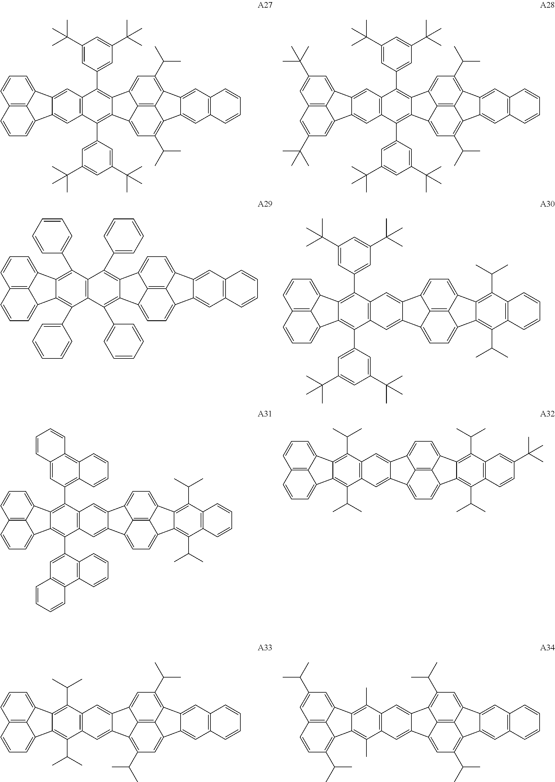


| TABLE 2 | |
 |
H1 |
 |
H2 |
 |
H3 |
 |
H4 |
 |
H5 |
 |
H6 |
 |
H7 |
 |
H8 |
 |
H9 |
 |
H10 |
 |
H11 |
 |
H12 |
 |
H13 |
 |
H14 |
 |
H15 |
 |
H16 |
 |
H17 |
 |
H18 |
 |
H19 |
 |
H20 |
 |
H21 |
 |
H22 |
 |
H23 |
 |
H24 |

(1) Synthesis of Compound E3

(1) Synthesis of Compound E8


| TABLE 3 | |||
| Thickness | |||
| Material | (nm) | ||
| Hole-transporting layer | G-1 | 30 |
| Electron-blocking layer | G-2 | 10 |
| Light-emitting layer | G-3 (host) | 30 |
| G-4 (assist) | ||
| Example Compound A7 | ||
| (guest) | ||
| (G-3:G-4:A7 = | ||
| 60:39.5:0.5 | ||
| (weight ratio)) | ||
| Hole-blocking layer | G-5 | 10 |
| Electron-transporting layer | G-6 | 30 |
| First metal electrode layer | LiF | 1 |
| Second metal electrode layer | Al | 100 |
| TABLE 4 | ||||||
| Luminous | ||||||
| Guest | efficiency | Voltage | ||||
| material | G-3 | G-4 | (cd/A) | (V) | ||
| Example 16 | A12 | H10 | H21 | 39 | 4.0 |
| Example 17 | A2 | H7 | H23 | 35 | 4.0 |
| Example 18 | A3 | H14 | H23 | 38 | 4.1 |
| Example 19 | A12 | H10 | H18 | 36 | 4.0 |
| Example 20 | A13 | H6 | H21 | 39 | 3.9 |
| Example 21 | A14 | H22 | H22 | 30 | 4.0 |
| Example 22 | A15 | H6 | H6 | 38 | 4.2 |
| Example 23 | A16 | H13 | H22 | 39 | 4.1 |
| Example 24 | A22 | H12 | H21 | 37 | 4.0 |
| Example 25 | A22 | H15 | H22 | 35 | 4.1 |
| Example 26 | A33 | H10 | H17 | 38 | 3.9 |
| Example 27 | B1 | H8 | H24 | 38 | 4.1 |

| TABLE 5 | |||
| Thickness | |||
| Material | (nm) | ||
| Hole-transporting layer | G-11 | 90 |
| Electron-blocking layer | G-12 | 10 |
| Light-emitting layer | G-13 (host) | 30 |
| G-14 (assist) | ||
| Example Compound A17 | ||
| (guest) | ||
| (G-13:G-14:A2 = | ||
| 60:39.5:0.5 | ||
| (weight ratio)) | ||
| Electron-transporting layer | G-15 | 10 |
| Electron-injecting layer | G-16 | 70 |
| Li | ||
| (G-16:Li = | ||
| 80:20 | ||
| (weight ratio)) | ||
| TABLE 6 | ||||||
| Luminous | ||||||
| Guest | efficiency | Voltage | ||||
| material | G-13 | G-14 | (cd/A) | (V) | ||
| Example 28 | A2 | H5 | H19 | 50 | 4.4 |
| Example 29 | A12 | H10 | H18 | 54 | 4.6 |
| Example 30 | A13 | H12 | H23 | 53 | 4.6 |
| Example 31 | A16 | H21 | H21 | 53 | 4.3 |
| Example 32 | A22 | H6 | H19 | 54 | 4.4 |


| TABLE 7 | |||
| Thickness | |||
| Material | (nm) | ||
| Hole-transporting layer | G-21 | 30 |
| Electron-blocking layer | G-22 | 10 |
| First light-emitting layer | G-23 (first host) | 20 |
| G-24 (first guest) | ||
| Example Compound A18 | ||
| (second guest) | ||
| (G-23:G-24:A14 = | ||
| 95:0.5:4.5 | ||
| (weight ratio)) | ||
| Second light-emitting layer | G-25 (second host) | 20 |
| G-26 (third guest) | ||
| (G-25:G-26 = | ||
| 96:4 | ||
| (weight ratio)) | ||
| Hole-blocking layer | G-27 | 10 |
| Electron-transporting layer | G-28 | 30 |
| First metal electrode layer | LiF | 1 |
| Second metal electrode layer | Al | 100 |
| TABLE 8 | ||||||
| Luminous | ||||||
| Guest | efficiency | Voltage | ||||
| material | G-23 | G-25 | (cd/A) | (V) | ||
| Example 33 | | H10 | H14 | 14 | 5.2 | |
| Example 34 | A12 | H10 | |
15 | 5.2 | |
| Example 35 | | H23 | H5 | 13 | 5.3 | |
| Example 36 | A18 | H21 | H12 | 13 | 5.1 | |
-
- 4 blue-light-emitting layer
- 5 green-light-emitting layer
- 6 red-light-emitting layer
- 17 TFT device
- 20 anode
- 21 organic compound layer
- 22 cathode
Claims (16)

Applications Claiming Priority (3)
| Application Number | Priority Date | Filing Date | Title |
|---|---|---|---|
| JP2011207325A JP5791445B2 (en) | 2011-09-22 | 2011-09-22 | Novel organic compound, organic light emitting device and display device having the same |
| JP2011-207325 | 2011-09-22 | ||
| PCT/JP2012/073244 WO2013042584A1 (en) | 2011-09-22 | 2012-09-05 | Novel organic compound, organic light-emitting device, and display apparatus |
Publications (2)
| Publication Number | Publication Date |
|---|---|
| US20140225968A1 US20140225968A1 (en) | 2014-08-14 |
| US9019328B2 true US9019328B2 (en) | 2015-04-28 |
Family
ID=47914355
Family Applications (1)
| Application Number | Title | Priority Date | Filing Date |
|---|---|---|---|
| US14/346,291 Active US9019328B2 (en) | 2011-09-22 | 2012-09-05 | Organic compound, organic light-emitting device, and display apparatus |
Country Status (9)
| Country | Link |
|---|---|
| US (1) | US9019328B2 (en) |
| EP (1) | EP2758363B1 (en) |
| JP (1) | JP5791445B2 (en) |
| KR (1) | KR101612650B1 (en) |
| CN (1) | CN103827065B (en) |
| BR (1) | BR112014005844B1 (en) |
| IN (1) | IN2014CN02838A (en) |
| RU (1) | RU2570577C2 (en) |
| WO (1) | WO2013042584A1 (en) |
Cited By (1)
| Publication number | Priority date | Publication date | Assignee | Title |
|---|---|---|---|---|
| US20150311441A1 (en) * | 2014-04-23 | 2015-10-29 | Canon Kabushiki Kaisha | Metal complex compound, and organic light-emitting element and display device containing the same |
Families Citing this family (16)
| Publication number | Priority date | Publication date | Assignee | Title |
|---|---|---|---|---|
| KR102383315B1 (en) | 2018-03-30 | 2022-04-06 | 캐논 가부시끼가이샤 | Organic light emitting element, display apparatus, image pickup apparatus, and illumination apparatus |
| CN112020778A (en) * | 2018-04-05 | 2020-12-01 | 出光兴产株式会社 | Organic electroluminescent element and electronic device |
| JP7182971B2 (en) * | 2018-09-21 | 2022-12-05 | キヤノン株式会社 | Organic compounds, organic light-emitting devices, display devices, imaging devices, electronic devices and mobile objects |
| JP7179564B2 (en) * | 2018-10-03 | 2022-11-29 | キヤノン株式会社 | Organic compounds and organic light-emitting devices |
| JP7254552B2 (en) * | 2019-02-13 | 2023-04-10 | キヤノン株式会社 | Organic compounds and organic light-emitting devices |
| JP7218261B2 (en) | 2019-09-05 | 2023-02-06 | キヤノン株式会社 | Organic compounds and organic light-emitting devices |
| CN114402454A (en) * | 2019-09-13 | 2022-04-26 | 出光兴产株式会社 | Organic electroluminescent element and electronic device |
| JPWO2021049651A1 (en) * | 2019-09-13 | 2021-03-18 | ||
| US11094886B2 (en) | 2019-09-13 | 2021-08-17 | Idemitsu Kosan Co., Ltd. | Organic electroluminescent element and electronic device |
| WO2021049658A1 (en) * | 2019-09-13 | 2021-03-18 | 出光興産株式会社 | Organic electroluminescent element and electronic device |
| WO2021049662A1 (en) * | 2019-09-13 | 2021-03-18 | 出光興産株式会社 | Organic electroluminescent element and electronic device |
| JP7218322B2 (en) | 2019-10-03 | 2023-02-06 | キヤノン株式会社 | organic compounds, organic light-emitting devices, display devices, imaging devices, lighting devices, mobile objects |
| CN114514629A (en) * | 2019-11-08 | 2022-05-17 | 出光兴产株式会社 | Organic electroluminescent element and electronic device |
| KR102455023B1 (en) * | 2019-12-16 | 2022-10-13 | 삼성에스디아이 주식회사 | Compound, synthesis method of the compound, hardmask composition, and method of forming patterns |
| CN111799386B (en) * | 2020-07-22 | 2023-07-14 | 京东方科技集团股份有限公司 | Light-emitting device and display device |
| KR20230117384A (en) * | 2020-12-02 | 2023-08-08 | 이데미쓰 고산 가부시키가이샤 | Organic electroluminescent elements and electronic devices |
Citations (7)
| Publication number | Priority date | Publication date | Assignee | Title |
|---|---|---|---|---|
| JP2002110354A (en) | 2000-09-28 | 2002-04-12 | Mitsui Chemicals Inc | Hydrocarbon compound and organic electroluminescent element |
| JP2008255095A (en) | 2007-03-09 | 2008-10-23 | Canon Inc | Fused ring aromatic compound and organic light-emitting element by using the same |
| JP2009149612A (en) | 2007-11-26 | 2009-07-09 | Tdk Corp | Compound for organic el element and organic el element |
| JP2009182039A (en) | 2008-01-29 | 2009-08-13 | Mitsui Chemicals Inc | Organic transistor |
| JP2012149012A (en) * | 2011-01-20 | 2012-08-09 | Canon Inc | Organic compound, organic light-emitting element and image display device |
| US20130048966A1 (en) * | 2011-08-23 | 2013-02-28 | Canon Kabushiki Kaisha | Condensed polycyclic compound and organic light emitting element including the same |
| US20140291660A1 (en) * | 2011-11-02 | 2014-10-02 | Udc Ireland Limited | Organic Electroluminescent Element, Material for Organic Electroluminescent Element and Light Emitting Device, Display Device, and Illumination Device, Each Employing Organic Electroluminescent Element |
Family Cites Families (5)
| Publication number | Priority date | Publication date | Assignee | Title |
|---|---|---|---|---|
| JP4467170B2 (en) * | 2000-11-22 | 2010-05-26 | 三井化学株式会社 | Hydrocarbon compounds and organic electroluminescent devices |
| JP4462753B2 (en) * | 2000-12-01 | 2010-05-12 | 三井化学株式会社 | Hydrocarbon compounds and organic electroluminescent devices |
| JP2009033069A (en) * | 2007-07-31 | 2009-02-12 | Mitsui Chemicals Inc | Organic transistor |
| RU2368641C2 (en) * | 2007-11-08 | 2009-09-27 | Некоммерческая организация Учреждение Институт проблем химической физики Российской академии наук (статус государственного учреждения) (ИПХФ РАН) | Electroluminescent material, containing organic luminescent substance |
| KR100922757B1 (en) * | 2008-02-19 | 2009-10-21 | 삼성모바일디스플레이주식회사 | An organic light emitting device |
-
2011
- 2011-09-22 JP JP2011207325A patent/JP5791445B2/en active Active
-
2012
- 2012-09-05 KR KR1020147009793A patent/KR101612650B1/en active IP Right Grant
- 2012-09-05 US US14/346,291 patent/US9019328B2/en active Active
- 2012-09-05 EP EP12833387.9A patent/EP2758363B1/en active Active
- 2012-09-05 IN IN2838CHN2014 patent/IN2014CN02838A/en unknown
- 2012-09-05 WO PCT/JP2012/073244 patent/WO2013042584A1/en active Application Filing
- 2012-09-05 BR BR112014005844-0A patent/BR112014005844B1/en active IP Right Grant
- 2012-09-05 RU RU2014115997/04A patent/RU2570577C2/en active
- 2012-09-05 CN CN201280045957.7A patent/CN103827065B/en active Active
Patent Citations (8)
| Publication number | Priority date | Publication date | Assignee | Title |
|---|---|---|---|---|
| JP2002110354A (en) | 2000-09-28 | 2002-04-12 | Mitsui Chemicals Inc | Hydrocarbon compound and organic electroluminescent element |
| JP2008255095A (en) | 2007-03-09 | 2008-10-23 | Canon Inc | Fused ring aromatic compound and organic light-emitting element by using the same |
| CN101541714A (en) | 2007-03-09 | 2009-09-23 | 佳能株式会社 | Fused ring aromatic compound and organic light-emitting device using same |
| JP2009149612A (en) | 2007-11-26 | 2009-07-09 | Tdk Corp | Compound for organic el element and organic el element |
| JP2009182039A (en) | 2008-01-29 | 2009-08-13 | Mitsui Chemicals Inc | Organic transistor |
| JP2012149012A (en) * | 2011-01-20 | 2012-08-09 | Canon Inc | Organic compound, organic light-emitting element and image display device |
| US20130048966A1 (en) * | 2011-08-23 | 2013-02-28 | Canon Kabushiki Kaisha | Condensed polycyclic compound and organic light emitting element including the same |
| US20140291660A1 (en) * | 2011-11-02 | 2014-10-02 | Udc Ireland Limited | Organic Electroluminescent Element, Material for Organic Electroluminescent Element and Light Emitting Device, Display Device, and Illumination Device, Each Employing Organic Electroluminescent Element |
Cited By (1)
| Publication number | Priority date | Publication date | Assignee | Title |
|---|---|---|---|---|
| US20150311441A1 (en) * | 2014-04-23 | 2015-10-29 | Canon Kabushiki Kaisha | Metal complex compound, and organic light-emitting element and display device containing the same |
Also Published As
| Publication number | Publication date |
|---|---|
| IN2014CN02838A (en) | 2015-07-03 |
| WO2013042584A1 (en) | 2013-03-28 |
| RU2570577C2 (en) | 2015-12-10 |
| EP2758363B1 (en) | 2017-07-05 |
| JP2013067586A (en) | 2013-04-18 |
| EP2758363A4 (en) | 2015-05-27 |
| RU2014115997A (en) | 2015-10-27 |
| KR101612650B1 (en) | 2016-04-14 |
| BR112014005844B1 (en) | 2020-12-15 |
| CN103827065A (en) | 2014-05-28 |
| CN103827065B (en) | 2015-12-23 |
| US20140225968A1 (en) | 2014-08-14 |
| EP2758363A1 (en) | 2014-07-30 |
| BR112014005844A2 (en) | 2017-03-28 |
| KR20140066227A (en) | 2014-05-30 |
| JP5791445B2 (en) | 2015-10-07 |
Similar Documents
| Publication | Publication Date | Title |
|---|---|---|
| US9019328B2 (en) | Organic compound, organic light-emitting device, and display apparatus | |
| US9590199B2 (en) | Organic compound, organic light emitting device, and image display device | |
| US8963813B2 (en) | Organic compound and organic light emitting device having the same | |
| US9240554B2 (en) | Organic compound, organic electroluminescence element, and image display device | |
| US8431711B2 (en) | Organic compound | |
| EP2569268B1 (en) | Novel organic compound and organic light-emitting device including the same | |
| US9397298B2 (en) | Organic compound, organic light-emitting device, and image display device | |
| KR101513789B1 (en) | Novel organic compound and organic light-emitting device including the same | |
| US9166173B2 (en) | Organic compound | |
| JP5704940B2 (en) | Organic compound, organic light emitting device and display device | |
| JP2012148987A (en) | Organic compound, organic light-emitting element, and display device |
Legal Events
| Date | Code | Title | Description |
|---|---|---|---|
| AS | Assignment |
Owner name: CANON KABUSHIKI KAISHA, JAPAN Free format text: ASSIGNMENT OF ASSIGNORS INTEREST;ASSIGNORS:KAMATANI, JUN;YAMADA, NAOKI;SAITOH, AKIHITO;SIGNING DATES FROM 20140225 TO 20140226;REEL/FRAME:032960/0570 |
|
| STCF | Information on status: patent grant |
Free format text: PATENTED CASE |
|
| MAFP | Maintenance fee payment |
Free format text: PAYMENT OF MAINTENANCE FEE, 4TH YEAR, LARGE ENTITY (ORIGINAL EVENT CODE: M1551); ENTITY STATUS OF PATENT OWNER: LARGE ENTITY Year of fee payment: 4 |
|
| MAFP | Maintenance fee payment |
Free format text: PAYMENT OF MAINTENANCE FEE, 8TH YEAR, LARGE ENTITY (ORIGINAL EVENT CODE: M1552); ENTITY STATUS OF PATENT OWNER: LARGE ENTITY Year of fee payment: 8 |