US9017202B2 - Drive train - Google Patents
Drive train Download PDFInfo
- Publication number
- US9017202B2 US9017202B2 US13/775,137 US201313775137A US9017202B2 US 9017202 B2 US9017202 B2 US 9017202B2 US 201313775137 A US201313775137 A US 201313775137A US 9017202 B2 US9017202 B2 US 9017202B2
- Authority
- US
- United States
- Prior art keywords
- pump
- freewheel
- drive shaft
- electrical machine
- drive train
- Prior art date
- Legal status (The legal status is an assumption and is not a legal conclusion. Google has not performed a legal analysis and makes no representation as to the accuracy of the status listed.)
- Expired - Fee Related
Links
Images


Classifications
-
- F—MECHANICAL ENGINEERING; LIGHTING; HEATING; WEAPONS; BLASTING
- F16—ENGINEERING ELEMENTS AND UNITS; GENERAL MEASURES FOR PRODUCING AND MAINTAINING EFFECTIVE FUNCTIONING OF MACHINES OR INSTALLATIONS; THERMAL INSULATION IN GENERAL
- F16H—GEARING
- F16H37/00—Combinations of mechanical gearings, not provided for in groups F16H1/00 - F16H35/00
- F16H37/02—Combinations of mechanical gearings, not provided for in groups F16H1/00 - F16H35/00 comprising essentially only toothed or friction gearings
- F16H37/06—Combinations of mechanical gearings, not provided for in groups F16H1/00 - F16H35/00 comprising essentially only toothed or friction gearings with a plurality of driving or driven shafts; with arrangements for dividing torque between two or more intermediate shafts
- F16H37/065—Combinations of mechanical gearings, not provided for in groups F16H1/00 - F16H35/00 comprising essentially only toothed or friction gearings with a plurality of driving or driven shafts; with arrangements for dividing torque between two or more intermediate shafts with a plurality of driving or driven shafts
-
- B—PERFORMING OPERATIONS; TRANSPORTING
- B60—VEHICLES IN GENERAL
- B60K—ARRANGEMENT OR MOUNTING OF PROPULSION UNITS OR OF TRANSMISSIONS IN VEHICLES; ARRANGEMENT OR MOUNTING OF PLURAL DIVERSE PRIME-MOVERS IN VEHICLES; AUXILIARY DRIVES FOR VEHICLES; INSTRUMENTATION OR DASHBOARDS FOR VEHICLES; ARRANGEMENTS IN CONNECTION WITH COOLING, AIR INTAKE, GAS EXHAUST OR FUEL SUPPLY OF PROPULSION UNITS IN VEHICLES
- B60K17/00—Arrangement or mounting of transmissions in vehicles
- B60K17/26—Arrangement or mounting of transmissions in vehicles characterised by arrangement, location, of type of freewheel device
-
- B—PERFORMING OPERATIONS; TRANSPORTING
- B60—VEHICLES IN GENERAL
- B60K—ARRANGEMENT OR MOUNTING OF PROPULSION UNITS OR OF TRANSMISSIONS IN VEHICLES; ARRANGEMENT OR MOUNTING OF PLURAL DIVERSE PRIME-MOVERS IN VEHICLES; AUXILIARY DRIVES FOR VEHICLES; INSTRUMENTATION OR DASHBOARDS FOR VEHICLES; ARRANGEMENTS IN CONNECTION WITH COOLING, AIR INTAKE, GAS EXHAUST OR FUEL SUPPLY OF PROPULSION UNITS IN VEHICLES
- B60K6/00—Arrangement or mounting of plural diverse prime-movers for mutual or common propulsion, e.g. hybrid propulsion systems comprising electric motors and internal combustion engines ; Control systems therefor, i.e. systems controlling two or more prime movers, or controlling one of these prime movers and any of the transmission, drive or drive units Informative references: mechanical gearings with secondary electric drive F16H3/72; arrangements for handling mechanical energy structurally associated with the dynamo-electric machine H02K7/00; machines comprising structurally interrelated motor and generator parts H02K51/00; dynamo-electric machines not otherwise provided for in H02K see H02K99/00
- B60K6/20—Arrangement or mounting of plural diverse prime-movers for mutual or common propulsion, e.g. hybrid propulsion systems comprising electric motors and internal combustion engines ; Control systems therefor, i.e. systems controlling two or more prime movers, or controlling one of these prime movers and any of the transmission, drive or drive units Informative references: mechanical gearings with secondary electric drive F16H3/72; arrangements for handling mechanical energy structurally associated with the dynamo-electric machine H02K7/00; machines comprising structurally interrelated motor and generator parts H02K51/00; dynamo-electric machines not otherwise provided for in H02K see H02K99/00 the prime-movers consisting of electric motors and internal combustion engines, e.g. HEVs
- B60K6/22—Arrangement or mounting of plural diverse prime-movers for mutual or common propulsion, e.g. hybrid propulsion systems comprising electric motors and internal combustion engines ; Control systems therefor, i.e. systems controlling two or more prime movers, or controlling one of these prime movers and any of the transmission, drive or drive units Informative references: mechanical gearings with secondary electric drive F16H3/72; arrangements for handling mechanical energy structurally associated with the dynamo-electric machine H02K7/00; machines comprising structurally interrelated motor and generator parts H02K51/00; dynamo-electric machines not otherwise provided for in H02K see H02K99/00 the prime-movers consisting of electric motors and internal combustion engines, e.g. HEVs characterised by apparatus, components or means specially adapted for HEVs
- B60K6/38—Arrangement or mounting of plural diverse prime-movers for mutual or common propulsion, e.g. hybrid propulsion systems comprising electric motors and internal combustion engines ; Control systems therefor, i.e. systems controlling two or more prime movers, or controlling one of these prime movers and any of the transmission, drive or drive units Informative references: mechanical gearings with secondary electric drive F16H3/72; arrangements for handling mechanical energy structurally associated with the dynamo-electric machine H02K7/00; machines comprising structurally interrelated motor and generator parts H02K51/00; dynamo-electric machines not otherwise provided for in H02K see H02K99/00 the prime-movers consisting of electric motors and internal combustion engines, e.g. HEVs characterised by apparatus, components or means specially adapted for HEVs characterised by the driveline clutches
- B60K6/383—One-way clutches or freewheel devices
-
- B—PERFORMING OPERATIONS; TRANSPORTING
- B60—VEHICLES IN GENERAL
- B60K—ARRANGEMENT OR MOUNTING OF PROPULSION UNITS OR OF TRANSMISSIONS IN VEHICLES; ARRANGEMENT OR MOUNTING OF PLURAL DIVERSE PRIME-MOVERS IN VEHICLES; AUXILIARY DRIVES FOR VEHICLES; INSTRUMENTATION OR DASHBOARDS FOR VEHICLES; ARRANGEMENTS IN CONNECTION WITH COOLING, AIR INTAKE, GAS EXHAUST OR FUEL SUPPLY OF PROPULSION UNITS IN VEHICLES
- B60K6/00—Arrangement or mounting of plural diverse prime-movers for mutual or common propulsion, e.g. hybrid propulsion systems comprising electric motors and internal combustion engines ; Control systems therefor, i.e. systems controlling two or more prime movers, or controlling one of these prime movers and any of the transmission, drive or drive units Informative references: mechanical gearings with secondary electric drive F16H3/72; arrangements for handling mechanical energy structurally associated with the dynamo-electric machine H02K7/00; machines comprising structurally interrelated motor and generator parts H02K51/00; dynamo-electric machines not otherwise provided for in H02K see H02K99/00
- B60K6/20—Arrangement or mounting of plural diverse prime-movers for mutual or common propulsion, e.g. hybrid propulsion systems comprising electric motors and internal combustion engines ; Control systems therefor, i.e. systems controlling two or more prime movers, or controlling one of these prime movers and any of the transmission, drive or drive units Informative references: mechanical gearings with secondary electric drive F16H3/72; arrangements for handling mechanical energy structurally associated with the dynamo-electric machine H02K7/00; machines comprising structurally interrelated motor and generator parts H02K51/00; dynamo-electric machines not otherwise provided for in H02K see H02K99/00 the prime-movers consisting of electric motors and internal combustion engines, e.g. HEVs
- B60K6/42—Arrangement or mounting of plural diverse prime-movers for mutual or common propulsion, e.g. hybrid propulsion systems comprising electric motors and internal combustion engines ; Control systems therefor, i.e. systems controlling two or more prime movers, or controlling one of these prime movers and any of the transmission, drive or drive units Informative references: mechanical gearings with secondary electric drive F16H3/72; arrangements for handling mechanical energy structurally associated with the dynamo-electric machine H02K7/00; machines comprising structurally interrelated motor and generator parts H02K51/00; dynamo-electric machines not otherwise provided for in H02K see H02K99/00 the prime-movers consisting of electric motors and internal combustion engines, e.g. HEVs characterised by the architecture of the hybrid electric vehicle
- B60K6/48—Parallel type
- B60K6/485—Motor-assist type
-
- F—MECHANICAL ENGINEERING; LIGHTING; HEATING; WEAPONS; BLASTING
- F16—ENGINEERING ELEMENTS AND UNITS; GENERAL MEASURES FOR PRODUCING AND MAINTAINING EFFECTIVE FUNCTIONING OF MACHINES OR INSTALLATIONS; THERMAL INSULATION IN GENERAL
- F16D—COUPLINGS FOR TRANSMITTING ROTATION; CLUTCHES; BRAKES
- F16D41/00—Freewheels or freewheel clutches
- F16D41/06—Freewheels or freewheel clutches with intermediate wedging coupling members between an inner and an outer surface
- F16D41/08—Freewheels or freewheel clutches with intermediate wedging coupling members between an inner and an outer surface with provision for altering the freewheeling action
- F16D41/086—Freewheels or freewheel clutches with intermediate wedging coupling members between an inner and an outer surface with provision for altering the freewheeling action the intermediate members being of circular cross-section and wedging by rolling
- F16D41/088—Freewheels or freewheel clutches with intermediate wedging coupling members between an inner and an outer surface with provision for altering the freewheeling action the intermediate members being of circular cross-section and wedging by rolling the intermediate members being of only one size and wedging by a movement not having an axial component, between inner and outer races, one of which is cylindrical
-
- F—MECHANICAL ENGINEERING; LIGHTING; HEATING; WEAPONS; BLASTING
- F16—ENGINEERING ELEMENTS AND UNITS; GENERAL MEASURES FOR PRODUCING AND MAINTAINING EFFECTIVE FUNCTIONING OF MACHINES OR INSTALLATIONS; THERMAL INSULATION IN GENERAL
- F16D—COUPLINGS FOR TRANSMITTING ROTATION; CLUTCHES; BRAKES
- F16D47/00—Systems of clutches, or clutches and couplings, comprising devices of types grouped under at least two of the preceding guide headings
- F16D47/04—Systems of clutches, or clutches and couplings, comprising devices of types grouped under at least two of the preceding guide headings of which at least one is a freewheel
-
- F—MECHANICAL ENGINEERING; LIGHTING; HEATING; WEAPONS; BLASTING
- F16—ENGINEERING ELEMENTS AND UNITS; GENERAL MEASURES FOR PRODUCING AND MAINTAINING EFFECTIVE FUNCTIONING OF MACHINES OR INSTALLATIONS; THERMAL INSULATION IN GENERAL
- F16H—GEARING
- F16H61/00—Control functions within control units of change-speed- or reversing-gearings for conveying rotary motion ; Control of exclusively fluid gearing, friction gearing, gearings with endless flexible members or other particular types of gearing
- F16H61/0021—Generation or control of line pressure
- F16H61/0025—Supply of control fluid; Pumps therefore
- F16H61/0028—Supply of control fluid; Pumps therefore using a single pump driven by different power sources
-
- B—PERFORMING OPERATIONS; TRANSPORTING
- B60—VEHICLES IN GENERAL
- B60K—ARRANGEMENT OR MOUNTING OF PROPULSION UNITS OR OF TRANSMISSIONS IN VEHICLES; ARRANGEMENT OR MOUNTING OF PLURAL DIVERSE PRIME-MOVERS IN VEHICLES; AUXILIARY DRIVES FOR VEHICLES; INSTRUMENTATION OR DASHBOARDS FOR VEHICLES; ARRANGEMENTS IN CONNECTION WITH COOLING, AIR INTAKE, GAS EXHAUST OR FUEL SUPPLY OF PROPULSION UNITS IN VEHICLES
- B60K6/00—Arrangement or mounting of plural diverse prime-movers for mutual or common propulsion, e.g. hybrid propulsion systems comprising electric motors and internal combustion engines ; Control systems therefor, i.e. systems controlling two or more prime movers, or controlling one of these prime movers and any of the transmission, drive or drive units Informative references: mechanical gearings with secondary electric drive F16H3/72; arrangements for handling mechanical energy structurally associated with the dynamo-electric machine H02K7/00; machines comprising structurally interrelated motor and generator parts H02K51/00; dynamo-electric machines not otherwise provided for in H02K see H02K99/00
- B60K6/20—Arrangement or mounting of plural diverse prime-movers for mutual or common propulsion, e.g. hybrid propulsion systems comprising electric motors and internal combustion engines ; Control systems therefor, i.e. systems controlling two or more prime movers, or controlling one of these prime movers and any of the transmission, drive or drive units Informative references: mechanical gearings with secondary electric drive F16H3/72; arrangements for handling mechanical energy structurally associated with the dynamo-electric machine H02K7/00; machines comprising structurally interrelated motor and generator parts H02K51/00; dynamo-electric machines not otherwise provided for in H02K see H02K99/00 the prime-movers consisting of electric motors and internal combustion engines, e.g. HEVs
- B60K6/22—Arrangement or mounting of plural diverse prime-movers for mutual or common propulsion, e.g. hybrid propulsion systems comprising electric motors and internal combustion engines ; Control systems therefor, i.e. systems controlling two or more prime movers, or controlling one of these prime movers and any of the transmission, drive or drive units Informative references: mechanical gearings with secondary electric drive F16H3/72; arrangements for handling mechanical energy structurally associated with the dynamo-electric machine H02K7/00; machines comprising structurally interrelated motor and generator parts H02K51/00; dynamo-electric machines not otherwise provided for in H02K see H02K99/00 the prime-movers consisting of electric motors and internal combustion engines, e.g. HEVs characterised by apparatus, components or means specially adapted for HEVs
- B60K6/26—Arrangement or mounting of plural diverse prime-movers for mutual or common propulsion, e.g. hybrid propulsion systems comprising electric motors and internal combustion engines ; Control systems therefor, i.e. systems controlling two or more prime movers, or controlling one of these prime movers and any of the transmission, drive or drive units Informative references: mechanical gearings with secondary electric drive F16H3/72; arrangements for handling mechanical energy structurally associated with the dynamo-electric machine H02K7/00; machines comprising structurally interrelated motor and generator parts H02K51/00; dynamo-electric machines not otherwise provided for in H02K see H02K99/00 the prime-movers consisting of electric motors and internal combustion engines, e.g. HEVs characterised by apparatus, components or means specially adapted for HEVs characterised by the motors or the generators
- B60K2006/262—Arrangement or mounting of plural diverse prime-movers for mutual or common propulsion, e.g. hybrid propulsion systems comprising electric motors and internal combustion engines ; Control systems therefor, i.e. systems controlling two or more prime movers, or controlling one of these prime movers and any of the transmission, drive or drive units Informative references: mechanical gearings with secondary electric drive F16H3/72; arrangements for handling mechanical energy structurally associated with the dynamo-electric machine H02K7/00; machines comprising structurally interrelated motor and generator parts H02K51/00; dynamo-electric machines not otherwise provided for in H02K see H02K99/00 the prime-movers consisting of electric motors and internal combustion engines, e.g. HEVs characterised by apparatus, components or means specially adapted for HEVs characterised by the motors or the generators the motor or generator are used as clutch, e.g. between engine and driveshaft
-
- B—PERFORMING OPERATIONS; TRANSPORTING
- B60—VEHICLES IN GENERAL
- B60K—ARRANGEMENT OR MOUNTING OF PROPULSION UNITS OR OF TRANSMISSIONS IN VEHICLES; ARRANGEMENT OR MOUNTING OF PLURAL DIVERSE PRIME-MOVERS IN VEHICLES; AUXILIARY DRIVES FOR VEHICLES; INSTRUMENTATION OR DASHBOARDS FOR VEHICLES; ARRANGEMENTS IN CONNECTION WITH COOLING, AIR INTAKE, GAS EXHAUST OR FUEL SUPPLY OF PROPULSION UNITS IN VEHICLES
- B60K25/00—Auxiliary drives
- B60K2025/005—Auxiliary drives driven by electric motors forming part of the propulsion unit
-
- F—MECHANICAL ENGINEERING; LIGHTING; HEATING; WEAPONS; BLASTING
- F16—ENGINEERING ELEMENTS AND UNITS; GENERAL MEASURES FOR PRODUCING AND MAINTAINING EFFECTIVE FUNCTIONING OF MACHINES OR INSTALLATIONS; THERMAL INSULATION IN GENERAL
- F16H—GEARING
- F16H57/00—General details of gearing
- F16H57/04—Features relating to lubrication or cooling or heating
- F16H57/0434—Features relating to lubrication or cooling or heating relating to lubrication supply, e.g. pumps ; Pressure control
- F16H57/0436—Pumps
- F16H57/0439—Pumps using multiple pumps with different power sources or a single pump with different power sources, e.g. one and the same pump may selectively be driven by either the engine or an electric motor
-
- Y—GENERAL TAGGING OF NEW TECHNOLOGICAL DEVELOPMENTS; GENERAL TAGGING OF CROSS-SECTIONAL TECHNOLOGIES SPANNING OVER SEVERAL SECTIONS OF THE IPC; TECHNICAL SUBJECTS COVERED BY FORMER USPC CROSS-REFERENCE ART COLLECTIONS [XRACs] AND DIGESTS
- Y02—TECHNOLOGIES OR APPLICATIONS FOR MITIGATION OR ADAPTATION AGAINST CLIMATE CHANGE
- Y02T—CLIMATE CHANGE MITIGATION TECHNOLOGIES RELATED TO TRANSPORTATION
- Y02T10/00—Road transport of goods or passengers
- Y02T10/60—Other road transportation technologies with climate change mitigation effect
- Y02T10/62—Hybrid vehicles
-
- Y02T10/6226—
-
- Y—GENERAL TAGGING OF NEW TECHNOLOGICAL DEVELOPMENTS; GENERAL TAGGING OF CROSS-SECTIONAL TECHNOLOGIES SPANNING OVER SEVERAL SECTIONS OF THE IPC; TECHNICAL SUBJECTS COVERED BY FORMER USPC CROSS-REFERENCE ART COLLECTIONS [XRACs] AND DIGESTS
- Y10—TECHNICAL SUBJECTS COVERED BY FORMER USPC
- Y10T—TECHNICAL SUBJECTS COVERED BY FORMER US CLASSIFICATION
- Y10T74/00—Machine element or mechanism
- Y10T74/19—Gearing
- Y10T74/19014—Plural prime movers selectively coupled to common output
Definitions
- the present invention relates to a drive train for a motor vehicle, in which a torque of a drive unit can be transferred to a motor vehicle transmission as well as to a pump, in particular a transmission oil pump for acting hydraulically on the motor vehicle transmission.
- a drive train is known from WO 2006/012995 A1, in which an internal combustion engine is connected to a drive shaft, wherein the drive shaft can be coupled through a first freewheel to a pump shaft of a transmission oil pump.
- An electrical machine can be coupled through a second freewheel to the pump shaft of the transmission oil pump.
- either the internal combustion engine or the electrical machine is coupled to the pump shaft through the freewheel, such that an adequate supply of oil for a motor vehicle transmission by the transmission oil pump can be ensured.
- a disadvantage of such a drive train is that the structural linkage of the transmission oil pump necessitates a comparatively large construction space, and the energy efficiency of the drive train is still insufficient.
- An object of the present invention is to provide a drive train for a motor vehicle in which a pump, in particular a transmission oil pump, can be linked by a simple structural arrangement.
- a pump in particular a transmission oil pump
- a drive train in accordance with the present invention for a motor vehicle, in particular a hybrid vehicle has a drive shaft that can be connected to an internal combustion engine, and a pump, in particular a transmission oil pump, that can be coupled to the drive shaft by means of a freewheel, which in particular can be switched.
- An electrical machine for driving the pump is also provided.
- the electrical machine is arranged in the flow line of power direction between the drive shaft and the pump, and is in parallel in the flow of power direction to the freewheel.
- the pump purely electrically, for example with the internal combustion engine turned off, in which case the freewheel is overrun in this operating state and interrupts a flow of power between the internal combustion engine and the pump past the electrical machine.
- the freewheel can lock up and provide a flow of power via the freewheel.
- boost operation is possible, in which in addition to the internal combustion engine the electrical machine can also transmit power to the pump.
- the stator of the electrical machine can rotate together with the speed of the drive shaft, and by means of the delivered electric power can bring about an additional increase of the speed of the pump shaft connected to the pump, which is coupled to the rotor of the electrical machine. Since a comparatively high speed can be applied to the pump even when a low speed is provided by the internal combustion engine, the pump can be dimensioned correspondingly smaller and can provide the necessary flow volume with the aid of the increased speed. This makes it possible to construct the pump smaller and more compactly, so that less space is required for the drive train.
- a switching element in particular a centrifugal clutch, is situated in series with the freewheel in the flow of power direction and parallel to the electrical machine in the flow of power direction.
- a centrifugal clutch By means of the centrifugal clutch, when the freewheel is locked, i.e., when there is a mechanical flow of power from the internal combustion engine to the pump, an interruption of the flow of power is realized when a particular limiting speed is reached. That prevents the pump from being subjected unintentionally to an excessive speed, which could result, for example, in damage to the pump or in unnecessarily high wear of the pump.
- a different switching element can also be used to optionally couple or uncouple the freewheel.
- an electrically operated clutch can be provided as a switching element, in which case the rotational speed can be measured with a speed sensor connected to the clutch, and the freewheel can be coupled or uncoupled depending on a predefined threshold speed. This makes it possible in particular, by means of suitable software, to set the threshold speed differently for different construction types of drive trains, and/or to vary it during operation depending on the situation.
- the switching element in the form of a centrifugal clutch is able to switch the freewheel depending on the speed of rotation.
- the speed n limit of the drive shaft is chosen so that a predefined maximum necessary pumping capacity of the pump is reached at the speed n limit of the drive shaft. That makes it possible to ensure proper operation of the pump, while mechanical energy that is not necessary for the proper operation of the pump is not consumed, so that this part of the energy can be used elsewhere. The efficiency of the drive train is thereby improved.
- the freewheel can be switched directly thereby.
- the switching of the freewheel can be effected, for example, by means of the electrical activation or the torque of the electrical machine.
- a freely switchable freewheel can determine particularly flexibly the operating point at which the freewheel is unlocked.
- the rotational speed ratio of the drive shaft is increased or reduced ahead of the pump in the flow of power direction.
- the additional increase or reduction of the speed ratio for the pump makes it possible to adapt and optimize the necessary dimensioning of the electrical machine and of the pump.
- an additional increase in ratio makes a greater speed possible for the pump shaft of the pump, so that the pump can be dimensioned smaller.
- a decrease in ratio enables lower torques in the electrical machine, so that the electrical machine can be dimensioned smaller and save construction space.
- the drive shaft is coupled with the pump through a planetary gear set for speed variation.
- the speed of the drive shaft for operating the pump can be varied essentially steplessly, in order to achieve an increase or reduction in ratio.
- the drive shaft is connected to a ring gear of the planetary gear set, while the electrical machine is connected to the ring gear and a sun gear of the planetary gear set, the pump being connected to a planet carrier of the planetary gear set.
- the electrical machine is also possible to integrate the electrical machine, the freewheel and/or the switching element into the planetary gear set, so that the required construction space is correspondingly small. For example, it is sufficient to extend the ring gear and/or the sun gear in the axial direction, in order to be able to link the rotor and the stator of the electrical machine, as well as the freewheel and/or the centrifugal clutch.
- the drive shaft is connected to a ring gear of the planetary gear set, while the electrical machine is connected to the ring gear and a planet carrier of the planetary gear set, the pump being connected to a sun gear of the planetary gear set.
- the electrical machine, as well as the freewheel and the switching element can be integrated simply into the planetary gear set, for example by extending the ring gear and/or the planet carrier in the axial direction in order to link the electrical machine, the freewheel, and/or the centrifugal clutch.
- the freewheel, and possibly a switching element provided in series with the freewheel are connected to the electrical machine in parallel to the planetary gear set.
- the freewheel, and the possibly provided switching element can thus be linked to the same functional elements of the planetary gear set as the electrical machine. That makes it possible to achieve parallel arrangement of the electrical machine with the freewheel and the possibly provided centrifugal clutch especially simply.
- the corresponding components of the planetary gear set can be extended correspondingly in the axial direction, in order to be able to link the rotor and the stator of the electrical machine, as well as the freewheel and/or the centrifugal clutch.
- the freewheel disengages to interrupt the flow of power when the speed of the drive shaft is lower than the speed of a shaft that can be coupled by means of the freewheel, where the freewheel otherwise locks to provide a flow of power.
- the effect of this is that the internal combustion engine is able to drive the pump, but the pump does not attempt to drive the internal combustion engine.
- the freewheel prevents the electrical energy provided by the electrical machine from being used for operating drive train, although the internal combustion engine supplies sufficient power.
- the present invention also relates to a motor vehicle, in particular a hybrid vehicle having an internal combustion engine and a vehicle transmission, where the internal combustion engine is connected to the vehicle transmission by means of a drive train, wherein the drive train can be designed and refined as described above. Because of the smaller construction space requirement of the drive train and the improved efficiency, the motor vehicle can be operated more energy efficiently and can make additional construction space available for additional components.
- FIG. 1 a schematic representation of a drive train according to a first embodiment of the present invention
- FIG. 2 a schematic representation of a drive train according to a second embodiment of the present invention
- FIG. 3 a schematic representation of drive train according to a third embodiment of the present invention.
- FIG. 4 a schematic cross-sectional view of a part of a drive train according to another embodiment of the present invention.
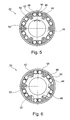
- FIG. 5 a schematic cross-sectional view of a switchable freewheel of the drive train of FIG. 4 in a locked operating state
- FIG. 6 a schematic cross-sectional view of a switchable freewheel of the drive train of FIG. 4 in an unlocked operating state.
- the drive train 10 depicted in FIG. 1 has a drive shaft 12 , which is coupled with an internal combustion engine 14 . Also provided is a pump designed as a transmission oil pump 16 , which can be coupled with drive shaft 12 by means of a pump shaft 18 . To this end, shaft 18 can be coupled through a freewheel 20 to drive shaft 12 .
- a switching element designed as centrifugal clutch 22 is provided, which interrupts a flow of power from drive shaft 12 to transmission oil pump 16 above a certain rotational speed.
- an electrical machine 24 is also provided, and in the flow of power direction parallel to freewheel 20 and to centrifugal clutch 22 .
- the order of freewheel 20 and centrifugal clutch 22 can also be exchanged.
- Electrical machine 24 has a stator 26 , which is connected to drive shaft 12 in a rotationally fixed connection. Stator 26 can optionally be powered by, for example, a motor vehicle battery.
- electrical machine 24 has a rotor 28 , which is connected to pump shaft 18 of transmission oil pump 16 in a rotationally fixed connection.
- Driving energy for transmission oil pump 16 can be provided by means of electrical machine 24 , in addition to or alternatively to driving energy from internal combustion engine 14 .
- transmission oil pump 16 can operate electrical machine 24 in generator mode, in order to produce electrical energy.
- drive shaft 12 is connected to a ring gear 32 , so that electrical machine 24 , as well as freewheel 20 and centrifugal clutch 22 are also connected to ring gear 32 .
- electrical machine 24 as well as freewheel 20 and centrifugal clutch 22
- sun gear 34 of planetary gear set 30
- the order of freewheel 20 and centrifugal clutch 22 can also be exchanged.
- Engaged with ring gear 32 and sun gear 34 is a planet gear 36 , which is connected to pump shaft 18 of transmission oil pump 16 by means of a planet carrier 38 .
- rotor 28 of electrical machine 24 is connected to sun gear 34
- stator 26 is connected to planet carrier 38 by means of a housing 40 , which also rotates.
- Pump shaft 18 of transmission oil pump 16 is coupled with ring gear 32 of planetary gear set 30 by means of a switchable freewheel 20 .
- a switching cage 42 connected to ring gear 32 is provided as the switching element, which locks or unlocks the switchable freewheel 20 .
- the switchable freewheel 20 depicted in FIG. 5 and FIG. 6 has an outer ring 44 and an inner ring 46 , between which clampable rollers 48 are situated. Two rollers 48 in each case are pressed apart from each other by means of a spring 50 situated between two adjacent rollers 48 , so that in the locked state ( FIG. 5 ) the rollers are clamped by means of a ramp 52 between outer ring 44 and inner ring 46 . This makes a power stream possible between outer ring 44 and inner ring 46 .
- switching cage 42 When electrical machine 24 is activated, switching cage 42 is moved relative to outer ring 44 in the circumferential direction, so that switching cage 42 presses the corresponding rollers 48 down from ramp 52 in the respective circumferential direction, whereby the power stream between outer ring 48 and inner ring 46 is interrupted ( FIG. 6 ). Since switching cage 42 can strike inner ring 46 in the circumferential direction, a power stream is provided from electrical machine 24 through switching cage 42 and inner ring 46 to transmission pump 16 .
Landscapes
- Engineering & Computer Science (AREA)
- General Engineering & Computer Science (AREA)
- Mechanical Engineering (AREA)
- Chemical & Material Sciences (AREA)
- Combustion & Propulsion (AREA)
- Transportation (AREA)
- Hybrid Electric Vehicles (AREA)
- Arrangement Of Transmissions (AREA)
- Retarders (AREA)
- One-Way And Automatic Clutches, And Combinations Of Different Clutches (AREA)
- Control Of Transmission Device (AREA)
Abstract
Description
Claims (11)
Applications Claiming Priority (4)
| Application Number | Priority Date | Filing Date | Title |
|---|---|---|---|
| DE102010035125.3 | 2010-08-23 | ||
| DE102010035125 | 2010-08-23 | ||
| DEPCT/DE2011/001513 | 2011-07-26 | ||
| PCT/DE2011/001513 WO2012025080A1 (en) | 2010-08-23 | 2011-07-26 | Drive train |
Publications (2)
| Publication Number | Publication Date |
|---|---|
| US20130274047A1 US20130274047A1 (en) | 2013-10-17 |
| US9017202B2 true US9017202B2 (en) | 2015-04-28 |
Family
ID=45557469
Family Applications (1)
| Application Number | Title | Priority Date | Filing Date |
|---|---|---|---|
| US13/775,137 Expired - Fee Related US9017202B2 (en) | 2010-08-23 | 2013-02-23 | Drive train |
Country Status (5)
| Country | Link |
|---|---|
| US (1) | US9017202B2 (en) |
| JP (1) | JP5850936B2 (en) |
| CN (1) | CN103210244B (en) |
| DE (2) | DE102011079800A1 (en) |
| WO (1) | WO2012025080A1 (en) |
Cited By (1)
| Publication number | Priority date | Publication date | Assignee | Title |
|---|---|---|---|---|
| WO2021008757A1 (en) * | 2019-07-16 | 2021-01-21 | Audi Ag | Belt pulley assembly |
Families Citing this family (14)
| Publication number | Priority date | Publication date | Assignee | Title |
|---|---|---|---|---|
| JP5380403B2 (en) | 2010-09-10 | 2014-01-08 | ジヤトコ株式会社 | Automatic transmission and hydraulic control device |
| DE102011013487B4 (en) * | 2011-03-10 | 2017-08-24 | Audi Ag | Motor vehicle with gearbox and transmission oil pump |
| CN103998811B (en) * | 2011-12-14 | 2016-10-05 | 舍弗勒技术股份两合公司 | clutch device |
| DE102012015082B4 (en) | 2012-07-30 | 2023-01-05 | Borgwarner Inc. | Freewheel device with switchable freewheel |
| US9791001B2 (en) * | 2012-12-27 | 2017-10-17 | Toyota Jidosha Kabushiki Kaisha | Power transmitting apparatus for vehicle |
| US9677646B2 (en) | 2013-12-25 | 2017-06-13 | Aisin Aw Co., Ltd. | Drive device that transfers rotation of at least one of a rotary electric machine and an internal combustion engine to an oil pump |
| DE102014200328A1 (en) * | 2014-01-10 | 2015-07-16 | Zf Friedrichshafen Ag | Oil pump drive for an axially parallel to the transmission input shaft arranged oil pump of an automatic transmission of a motor vehicle |
| DE102014009857A1 (en) * | 2014-07-03 | 2016-01-07 | Man Truck & Bus Ag | Drive device for a motor vehicle |
| CN105465296B (en) * | 2014-07-28 | 2020-01-03 | 舍弗勒技术股份两合公司 | Electric stepless speed variator |
| US9981543B2 (en) * | 2014-09-18 | 2018-05-29 | Moog Inc. | Hybrid power module |
| FR3029464A1 (en) * | 2014-12-08 | 2016-06-10 | Peugeot Citroen Automobiles Sa | POWERTRAIN COMPRISING AN OIL PUMP DRIVEN BY A THERMAL MOTOR AND AN ELECTRIC MACHINE |
| DE102015221891A1 (en) * | 2015-11-06 | 2017-05-11 | Continental Automotive Gmbh | Conveying device for conveying oil |
| DE102016209432A1 (en) | 2016-05-31 | 2017-11-30 | Zf Friedrichshafen Ag | Transmission for an oil pump drive of a motor vehicle |
| DE102018211799B4 (en) * | 2018-07-16 | 2021-05-12 | Hanon Systems Efp Deutschland Gmbh | Pump arrangement for a motor vehicle |
Citations (6)
| Publication number | Priority date | Publication date | Assignee | Title |
|---|---|---|---|---|
| DE19923316A1 (en) | 1999-05-21 | 2000-11-23 | Zahnradfabrik Friedrichshafen | Drive system for motor vehicle, having starter- and generator unit sealingly arranged in casing, in area, in which drive shaft, or shaft connected with it, steps through casing |
| US20050187066A1 (en) | 2004-02-24 | 2005-08-25 | Moses Robert L. | Integrated electric motor-driven oil pump for automatic transmissions in hybrid applications |
| WO2006012995A1 (en) | 2004-07-28 | 2006-02-09 | Daimler Chrysler Ag | Drive train comprising an electrically driven oil pump |
| WO2006089376A1 (en) | 2005-02-28 | 2006-08-31 | Nt Consulting International Pty Limited | Drive system with fluid pump |
| DE102007043737A1 (en) | 2007-09-13 | 2009-03-26 | Daimler Ag | drive module |
| US7828096B2 (en) * | 2006-07-14 | 2010-11-09 | Zf Friedrichshafen Ag | Hybrid drive for a vehicle |
Family Cites Families (3)
| Publication number | Priority date | Publication date | Assignee | Title |
|---|---|---|---|---|
| JP2860772B2 (en) * | 1995-06-06 | 1999-02-24 | 株式会社エクォス・リサーチ | Hybrid vehicle |
| DE102006008430A1 (en) * | 2006-02-23 | 2007-08-30 | Zf Friedrichshafen Ag | Drive device for oil pump, has electric motor arranged outside of pump housing and drivingly connected with inner wheel by torque proof driving connection, where inner wheel is located and driven in pump housing |
| JP4369966B2 (en) * | 2007-07-18 | 2009-11-25 | アイシン・エィ・ダブリュ株式会社 | Hybrid vehicle drive device |
-
2011
- 2011-07-26 DE DE102011079800A patent/DE102011079800A1/en not_active Withdrawn
- 2011-07-26 WO PCT/DE2011/001513 patent/WO2012025080A1/en active Application Filing
- 2011-07-26 CN CN201180040598.1A patent/CN103210244B/en not_active Expired - Fee Related
- 2011-07-26 DE DE112011102774T patent/DE112011102774A5/en not_active Withdrawn
- 2011-07-26 JP JP2013525135A patent/JP5850936B2/en not_active Expired - Fee Related
-
2013
- 2013-02-23 US US13/775,137 patent/US9017202B2/en not_active Expired - Fee Related
Patent Citations (8)
| Publication number | Priority date | Publication date | Assignee | Title |
|---|---|---|---|---|
| DE19923316A1 (en) | 1999-05-21 | 2000-11-23 | Zahnradfabrik Friedrichshafen | Drive system for motor vehicle, having starter- and generator unit sealingly arranged in casing, in area, in which drive shaft, or shaft connected with it, steps through casing |
| US6746354B1 (en) * | 1999-05-21 | 2004-06-08 | Zf Friedrichshafen Ag | Drive system for a motor vehicle |
| US20050187066A1 (en) | 2004-02-24 | 2005-08-25 | Moses Robert L. | Integrated electric motor-driven oil pump for automatic transmissions in hybrid applications |
| WO2006012995A1 (en) | 2004-07-28 | 2006-02-09 | Daimler Chrysler Ag | Drive train comprising an electrically driven oil pump |
| US20070149338A1 (en) | 2004-07-28 | 2007-06-28 | Norbert Ebner | Drive train |
| WO2006089376A1 (en) | 2005-02-28 | 2006-08-31 | Nt Consulting International Pty Limited | Drive system with fluid pump |
| US7828096B2 (en) * | 2006-07-14 | 2010-11-09 | Zf Friedrichshafen Ag | Hybrid drive for a vehicle |
| DE102007043737A1 (en) | 2007-09-13 | 2009-03-26 | Daimler Ag | drive module |
Cited By (1)
| Publication number | Priority date | Publication date | Assignee | Title |
|---|---|---|---|---|
| WO2021008757A1 (en) * | 2019-07-16 | 2021-01-21 | Audi Ag | Belt pulley assembly |
Also Published As
| Publication number | Publication date |
|---|---|
| DE112011102774A5 (en) | 2013-06-13 |
| US20130274047A1 (en) | 2013-10-17 |
| CN103210244B (en) | 2016-12-21 |
| JP5850936B2 (en) | 2016-02-03 |
| CN103210244A (en) | 2013-07-17 |
| DE102011079800A1 (en) | 2012-02-23 |
| WO2012025080A1 (en) | 2012-03-01 |
| JP2013542377A (en) | 2013-11-21 |
Similar Documents
| Publication | Publication Date | Title |
|---|---|---|
| US9017202B2 (en) | Drive train | |
| JP6087964B2 (en) | Drivetrain for hybrid vehicles | |
| US9475481B2 (en) | Powertrain for a vehicle | |
| US8777790B2 (en) | Continuously variable transmission device having power split | |
| US7727100B2 (en) | Hybrid powertrain with efficient electric-only mode | |
| US7250017B2 (en) | Auxiliary machine driven by engine and motor and capable of starting engine | |
| EP2094516B1 (en) | Hybrid power output system | |
| US8328672B2 (en) | Power unit | |
| EP1216871A2 (en) | Oil pump power in hybrid drive system | |
| US8562469B2 (en) | Hybrid power train having epicyclic type clutch device | |
| JP2005312295A (en) | Double-structure power drive system with mixed serial/parallel configuration | |
| CN105473365A (en) | Drive train for a hybrid vehicle | |
| CN109421530A (en) | Electronic (4WD) four-wheel drive device | |
| EP2861846B1 (en) | Supercharger assembly | |
| JP2008546593A (en) | Hybrid gearbox | |
| US20190291566A1 (en) | Power transmission structure of hybrid vehicle with one motor generator and three clutches | |
| JP2010083230A (en) | Hybrid drive device | |
| JP2014231770A (en) | Oil pump device | |
| JP2010083231A (en) | Hybrid drive device | |
| JP5682462B2 (en) | Lubrication device | |
| KR20090062320A (en) | Air conditioner driving system of hybrid electric vehicle | |
| US10059189B2 (en) | Electric machine with variable torque drive | |
| JP2005001544A (en) | Accessory driving device for idling stop vehicle | |
| US8900094B2 (en) | Engine damper bypass for hybrid powertrains | |
| CN111301144A (en) | Automobile hybrid power coupling system and vehicle |
Legal Events
| Date | Code | Title | Description |
|---|---|---|---|
| AS | Assignment |
Owner name: SCHAEFFLER TECHNOLOGIES AG & CO. KG, GERMANY Free format text: ASSIGNMENT OF ASSIGNORS INTEREST;ASSIGNOR:GOTZ, ANDREAS;REEL/FRAME:030828/0886 Effective date: 20130624 |
|
| STCF | Information on status: patent grant |
Free format text: PATENTED CASE |
|
| AS | Assignment |
Owner name: SCHAEFFLER TECHNOLOGIES GMBH & CO. KG, GERMANY Free format text: MERGER AND CHANGE OF NAME;ASSIGNORS:SCHAEFFLER TECHNOLOGIES AG & CO. KG;SCHAEFFLER VERWALTUNGS 5 GMBH;REEL/FRAME:037732/0228 Effective date: 20131231 Owner name: SCHAEFFLER TECHNOLOGIES AG & CO. KG, GERMANY Free format text: CHANGE OF NAME;ASSIGNOR:SCHAEFFLER TECHNOLOGIES GMBH & CO. KG;REEL/FRAME:037732/0347 Effective date: 20150101 |
|
| AS | Assignment |
Owner name: SCHAEFFLER TECHNOLOGIES AG & CO. KG, GERMANY Free format text: CORRECTIVE ASSIGNMENT TO CORRECT THE PROPERTY NUMBERS PREVIOUSLY RECORDED ON REEL 037732 FRAME 0347. ASSIGNOR(S) HEREBY CONFIRMS THE APP. NO. 14/553248 SHOULD BE APP. NO. 14/553258;ASSIGNOR:SCHAEFFLER TECHNOLOGIES GMBH & CO. KG;REEL/FRAME:040404/0530 Effective date: 20150101 |
|
| MAFP | Maintenance fee payment |
Free format text: PAYMENT OF MAINTENANCE FEE, 4TH YEAR, LARGE ENTITY (ORIGINAL EVENT CODE: M1551); ENTITY STATUS OF PATENT OWNER: LARGE ENTITY Year of fee payment: 4 |
|
| FEPP | Fee payment procedure |
Free format text: MAINTENANCE FEE REMINDER MAILED (ORIGINAL EVENT CODE: REM.); ENTITY STATUS OF PATENT OWNER: LARGE ENTITY |
|
| LAPS | Lapse for failure to pay maintenance fees |
Free format text: PATENT EXPIRED FOR FAILURE TO PAY MAINTENANCE FEES (ORIGINAL EVENT CODE: EXP.); ENTITY STATUS OF PATENT OWNER: LARGE ENTITY |
|
| STCH | Information on status: patent discontinuation |
Free format text: PATENT EXPIRED DUE TO NONPAYMENT OF MAINTENANCE FEES UNDER 37 CFR 1.362 |
|
| FP | Lapsed due to failure to pay maintenance fee |
Effective date: 20230428 |