US9013833B2 - Non-circular feature for boss tower engagement - Google Patents
Non-circular feature for boss tower engagement Download PDFInfo
- Publication number
- US9013833B2 US9013833B2 US13/796,767 US201313796767A US9013833B2 US 9013833 B2 US9013833 B2 US 9013833B2 US 201313796767 A US201313796767 A US 201313796767A US 9013833 B2 US9013833 B2 US 9013833B2
- Authority
- US
- United States
- Prior art keywords
- aperture
- actuator arm
- boss tower
- circular
- base plate
- Prior art date
- Legal status (The legal status is an assumption and is not a legal conclusion. Google has not performed a legal analysis and makes no representation as to the accuracy of the status listed.)
- Active
Links
- 239000000725 suspension Substances 0.000 claims abstract description 38
- 230000006835 compression Effects 0.000 claims abstract description 13
- 238000007906 compression Methods 0.000 claims abstract description 13
- 238000000034 method Methods 0.000 claims abstract description 10
- 238000009825 accumulation Methods 0.000 description 6
- 230000000712 assembly Effects 0.000 description 3
- 238000000429 assembly Methods 0.000 description 3
- 230000002463 transducing effect Effects 0.000 description 3
- 238000005452 bending Methods 0.000 description 2
- 230000001788 irregular Effects 0.000 description 2
- 239000000463 material Substances 0.000 description 2
- 238000013500 data storage Methods 0.000 description 1
- 230000003247 decreasing effect Effects 0.000 description 1
- 238000009987 spinning Methods 0.000 description 1
Images



Classifications
-
- G—PHYSICS
- G11—INFORMATION STORAGE
- G11B—INFORMATION STORAGE BASED ON RELATIVE MOVEMENT BETWEEN RECORD CARRIER AND TRANSDUCER
- G11B5/00—Recording by magnetisation or demagnetisation of a record carrier; Reproducing by magnetic means; Record carriers therefor
- G11B5/48—Disposition or mounting of heads or head supports relative to record carriers ; arrangements of heads, e.g. for scanning the record carrier to increase the relative speed
- G11B5/4806—Disposition or mounting of heads or head supports relative to record carriers ; arrangements of heads, e.g. for scanning the record carrier to increase the relative speed specially adapted for disk drive assemblies, e.g. assembly prior to operation, hard or flexible disk drives
- G11B5/4813—Mounting or aligning of arm assemblies, e.g. actuator arm supported by bearings, multiple arm assemblies, arm stacks or multiple heads on single arm
-
- Y—GENERAL TAGGING OF NEW TECHNOLOGICAL DEVELOPMENTS; GENERAL TAGGING OF CROSS-SECTIONAL TECHNOLOGIES SPANNING OVER SEVERAL SECTIONS OF THE IPC; TECHNICAL SUBJECTS COVERED BY FORMER USPC CROSS-REFERENCE ART COLLECTIONS [XRACs] AND DIGESTS
- Y10—TECHNICAL SUBJECTS COVERED BY FORMER USPC
- Y10T—TECHNICAL SUBJECTS COVERED BY FORMER US CLASSIFICATION
- Y10T29/00—Metal working
- Y10T29/49—Method of mechanical manufacture
- Y10T29/49826—Assembling or joining
- Y10T29/49908—Joining by deforming
- Y10T29/49925—Inward deformation of aperture or hollow body wall
Definitions
- Hard disk drive systems typically include one or more data storage disks.
- a transducing head carried by a slider is used to read from and write to a data track on a disc.
- the slider is carried by an arm assembly that includes an actuator arm and a suspension assembly.
- a swaging process is a common material processing technique used to connect the suspension assembly to the actuator arm.
- the suspension assembly includes a boss tower configured to fit within an aperture in the actuator arm. When a swage ball is passed through the boss tower when fitted in the arm aperture, the boss tower expands contacting the aperture surface and creating a frictional engagement that connects the suspension assembly to the actuator arm.
- One particular embodiment of this disclosure is a head stack assembly comprising an actuator arm having an aperture therein, a head suspension assembly comprising a load beam having a mounting region with an aperture therein, and a base plate adapted to attach the head suspension assembly to the actuator arm, with the base plate comprising a boss tower having an outside surface and a swaging hole.
- One of the actuator arm aperture, the boss tower outside surface or the swaging hole is non-circular.
- FIG. 1 is a perspective view of an exemplary hard disk drive (HDD) system.
- HDD hard disk drive
- FIG. 2 is a perspective view of an exploded head stack assembly.
- FIG. 3 is a side sectional view of the base plate, load beam and actuator arm prior to swaging.
- FIG. 4 is a top plan view of the base plate, load beam and actuator arm.
- FIG. 5 is a top plan view of a base plate and actuator arm, in accordance with an embodiment of the present disclosure.
- FIG. 6 is a top plan view of a base plate and actuator arm, in accordance with another embodiment of the present disclosure.
- FIG. 7 is a top plan view of a base plate and actuator arm, in accordance with another embodiment of the present disclosure.
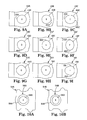
- FIGS. 8A-8H are top plan views of various embodiments of base plates in accordance with the present disclosure.
- FIGS. 9A-9I are top plan views of various embodiments of actuator arms in accordance with the present disclosure.
- FIGS. 10A-10B are top plan views of various embodiments of base plates in accordance with the present disclosure.
- FIGS. 11A-11C are examples of “circular-in-nature” shapes.
- the present invention relates to disk drives. More particularly, the invention provides a head-gimbal assembly that is attached to an actuator arm by a swaging process.
- the invention is applied to hard disk apparatus, but it would be recognized that the invention has a much broader range of applicability.
- the swaging process is a material processing technique used to connect various elements; for a hard disk apparatus, swaging is commonly used to form a head stack assembly.
- a boss tower is expanded to couple a load beam of a head gimbal assembly to an actuator arm or E-block.
- at least one of the head stack assembly engagement surfaces i.e., the boss tower outer surface, the boss tower swage hole, or the actuator arm aperture
- the non-circular engagement surface reduces distortion and bending of the actuator arm often experienced when swaging circular engagement surfaces, by producing unequal compression forces in the pitch and roll directions. The result is improved overall quality of the head stack assembly due to decreased distortion (e.g., bending up or down) of the actuator arm.
- FIG. 1 is a perspective view of an exemplary hard disk drive (HDD) system 20 that includes at least one magnetic storage disk 22 configured to rotate about an axis 24 , an actuation motor 26 (e.g., a voice coil motor), an actuator arm 28 , a suspension assembly 30 that includes a load beam, and a slider 32 carrying a transducing or read/write head (not shown). Slider 32 is supported by suspension assembly 30 , which in turn is supported by actuator arm 28 . Together, actuator arm 28 , suspension assembly 30 and slider 32 form a head stack assembly (HSA).
- HDD hard disk drive
- Actuation motor 26 is configured to pivot actuator arm 28 about an axis 34 , in order to sweep suspension 30 and slider 32 in an arc across a surface of rotating disk 22 with slider 32 “sliding” or “flying” across disk 22 on a cushion of air, often referred to as an air bearing.
- the read/write head carried by slider 32 can be positioned relative to selected concentric data tracks 36 of disk 22 by a piezoelectric microactuator, not seen in FIG. 1 .
- a stack of co-rotating disks 22 can be provided, with additional actuator arms 28 , suspension assemblies 30 , and sliders 32 carrying read/write heads for reading and writing at top and bottom surfaces of each disk 22 in the stack.
- a structure having multiple actuator arms 28 , suspension assemblies 30 and slider 32 is often referred to as an E-block.
- the present disclosure provides an attachment system for producing the head stack assembly (HSA) of HDD system 20 ; that is, the present disclosure provides a system for attaching together the various elements that form the HSA.
- HSA head stack assembly
- FIG. 2 is an exploded, isometric view of a head stack assembly (HSA) 40 including a load beam 42 , actuator arm 28 and a base plate 44 with a boss tower 46 .
- HSA 40 includes a flexure 50 to which slider 32 carrying a transducing or read/write head is to be mounted; flexure 50 may be attached to load beam 42 by any conventional mechanism or may be integral with load beam 42 .
- load beam 42 , flexure 50 and slider 32 are referred to as a head suspension assembly. Flexure 50 allows pitch and roll motion of slider 32 and the read/write head as they move over the data tracks 36 of disk 22 ( FIG. 1 ).
- Load beam 42 includes a mounting region 52 at a proximal end, a rigid region 54 adjacent to a distal end and a spring region 56 between the mounting region 52 and rigid region 54 .
- An aperture 60 is present in mounting region 52 .
- Spring region 56 is relatively resilient and provides a downward bias force at the distal tip of load beam 42 for holding the slider 32 with read/write head near a spinning disk in opposition to an upward force created by the air bearing over the disc.
- HSA 40 is typically coupled to actuation motor 26 ( FIG. 1 ) via actuator arm 28 that is attached to mounting region 52 of load beam 42 .
- a swage-type attachment is used to couple load beam 42 (at mounting region 52 ) to actuator arm 28 .
- Aperture 58 of actuator arm 28 and aperture 60 of load beam 42 are shaped and sized to receive boss tower 46 of base plate 44 therethrough.
- Boss tower 46 has an outer surface 64 and a swaging aperture or hole 48 that passes through boss tower 46 and base plate 44 . In some embodiments, the entire height of outer surface 64 is perpendicular to the base from which boss tower 46 extends.
- actuator arm 28 To swage load beam 42 to actuator arm 28 , actuator arm 28 , load beam 42 and base plate 44 are aligned with boss tower 46 inserted through load beam aperture 60 and actuator arm aperture 58 . As shown in FIG. 3 , mounting region 52 is sandwiched between base plate 44 (specifically, a surface 62 of base plate 44 ) and actuator arm 28 (specifically, a surface 63 of arm 28 ). Outside surface 64 of boss tower 46 is sized to fit within inner surface 68 of aperture 58 of actuator arm 28 . Outside surface 64 is typically adjacent to inner surface 68 , although the amount of engagement before swaging may vary.
- One or more swaging balls 70 are then forced through swage hole 48 to expand boss tower 46 in actuator arm aperture 58 . This expansion creates a frictional attachment interface between outside surface 64 of boss tower 46 and interior surface 68 of actuator arm aperture 58 . In some embodiments, a frictional attachment may also occur at load beam aperture 60 .
- swaging ball 70 When passed through swage hole 48 and apertures 58 , 60 , swaging ball 70 typically engages the inner surface of swage hole 48 (which is the inner surface of boss tower 46 ) generating an outwardly directed force against the surface and deforming boss tower 46 so that outer surface 64 frictionally engages inner surface 68 of arm aperture 58 . If swage hole 48 and swaging ball 70 are symmetrical, the force will radiate concentrically outward. A subsequent swaging ball 70 of greater diameter can then be used to further expand boss tower 46 and increase the engagement between surface 64 and surface 68 .
- FIG. 4 illustrates an enlarged view of a portion of HSA 40 , having actuator arm 28 connected to load beam 42 via boss tower 46 of base plate 44 .
- assembly 40 has an axis in the longitudinal direction x (referred to as the x-axis) and an axis in the lateral direction y (referred to as the y-axis) intersecting at the center of swage hole 48 and boss tower 46 .
- the surfaces that form the swaged frictional fit between the boss tower (e.g., boss tower 48 ) and the actuator arm (e.g., arm 28 ) are different; that is, prior to swaging, one of the surfaces of the boss tower or of the actuator arm is not circular.
- the boss tower outer surface e.g., surface 64
- the inner surface of the arm aperture e.g., inner surface 68
- the boss tower swage hole surface e.g., hole 48
- the inner surface of the arm aperture e.g., inner surface 68
- the boss tower outer surface may have the same or different shape that the swage hole (e.g., swage hole 48 ); i.e., they both may be non-circular or only one may be non-circular.
- the inner surface of the arm aperture e.g., inner surface 68
- the boss tower outer surface e.g., surface 64
- the two surface shapes are selected to reduce the interference of the boss tower and the arm aperture, which results in unequal compression force during and after swaging in the pitch direction (i.e., x-direction) and roll direction (i.e., y-direction).
- FIGS. 5 through 7 illustrate three embodiments of suspension assemblies, or portions thereof, having one of the surfaces that form the swaged frictional fit be non-circular.
- the non-circular surface is oval, when viewed in the top plan view, and results in reduced compression in the longitudinal direction (x-direction) of the arm when swaged.
- actuator arm 128 has a circular aperture 158 therein, into which is inserted a boss tower 146 of base plate 144 .
- Boss tower 146 has a circular swage hole 148 but a non-circular outer surface 164 .
- Outer surface 164 has an oval or elliptical shape, with the longer axis of the shape extending laterally in the y-direction.
- the wall between swage hole 148 and outer surface 164 has a varying thickness around boss tower 146 .
- actuator arm 228 has a non-circular aperture 258 therein, into which is inserted a boss tower 246 of base plate 244 .
- Boss tower 246 has a circular swage hole 248 and a circular outer surface 264 , so that the wall thickness of boss tower 246 is constant around boss tower 246 .
- Aperture 258 has an oval or elliptical shape, with the longer axis of the shape extending longitudinally in the x-direction.
- actuator arm 328 has a circular aperture 358 therein, into which is inserted a boss tower 346 of base plate 344 .
- Boss tower 346 has a circular outer surface 364 but a non-circular swage hole 348 .
- Swage hole 348 has an oval or elliptical shape, with the longer axis of the shape extending longitudinally in the x-direction.
- the wall between swage hole 348 and outer surface 364 has a varying thickness.
- Non-illustrated, but an alternate suitable configuration would have the boss tower having a non-circular swage hole (e.g., oval or elliptical) and a corresponding non-circular outer surface, so that the wall thickness of the boss tower is constant.
- the longer axis of the non-circular boss tower extends laterally in the y-direction.
- Such a boss tower would be used with a circular aperture in the actuator arm.
- the non-circular shape in any of the boss tower swage hole, boss tower outer surface or actuator arm aperture is selected to provide an asymmetric engagement of the boss tower and the actuator arm hole, which produces unequal compression force in the pitch direction (longitudinal or x-direction in FIGS. 5-7 ) and roll direction (lateral or y-direction in FIGS. 5-7 ).
- a preferred non-circular shape is oval or elliptical, other non-circular shapes, symmetrical and non-symmetrical, regular and irregular can be used.
- FIGS. 8A-8H , FIG. 9A-9I , and FIGS. 10A and 10B illustrate various alternate non-circular shapes for a boss tower engagement surfaces.
- FIGS. 8A-8H illustrate eight different suitable shapes for the outer surface of the boss tower.
- the following elements are present in each of these figures: actuator arm 444 , boss tower 446 , swage hole 448 in the boss tower, and outer surface 464 of the boss tower.
- the elements are distinguished among the various figures by the alphabetic designator subsequent to the numeral; for example, in FIG. 8A each of the numerals designating an element ends in “A”, in FIG. 8B each of the numerals designating an element ends in “B”, etc., except however, in these figures, swage hole 448 is always the same, thus no alphabetic designator is included.
- a head stack assembly e.g., HSA 40 of FIGS.
- these illustrated boss tower shapes include shapes that are symmetric in both the longitudinal direction of the arm and in the lateral direction of the arm, symmetric in the longitudinal direction of the arm yet asymmetric in the lateral direction of the arm, symmetric in the lateral direction of the arm yet asymmetric in the longitudinal direction of the arm, and asymmetric in both the longitudinal direction of the arm and in the lateral direction of the arm.
- FIGS. 8A-8H shows a base plate 444 A-H having a boss tower 446 A-H with a circular swage hole 448 and a non-circular outer surface 464 A-H, resulting in a wall with a non-constant thickness around the boss tower.
- FIGS. 8A , 8 B and 8 C illustrate examples of boss tower engagement surfaces that are symmetrical around a longitudinal axis through the swage hole of the base plate and the resulting suspension assembly into which the base plate will be incorporated.
- FIG. 8A shows a base plate 444 A having boss tower 446 A with a circular swage hole 448 and an outer surface 464 A that is non-circular; in this embodiment, a surface portion 465 A has an arcuate contour that provides the non-circular shape to outer surface 464 A.
- Surface portion 465 A occupies approximately one-third of the distal-most outer surface 464 A and is defined by a radius different than the radius of the other two-thirds of outer surface 464 A.
- Boss tower 446 A at surface portion 465 A has a lesser thickness than the other two-thirds of boss tower 446 A.
- FIG. 8B shows a base plate 444 B that has boss tower 446 B with a circular swage hole 448 and an outer surface 464 B that is non-circular; in this embodiment, an arcuate surface portion 465 B provides the non-circular shape to outer surface 464 B.
- Surface portion 465 B occupies approximately one-third of the proximal-most outer surface 464 B and is defined by a radius different than the radius of the other two-thirds of outer surface 464 B.
- Boss tower 446 B at surface portion 465 B has a lesser thickness than the other two-thirds of boss tower 446 B.
- the thinned portion of boss tower 446 B (at surface portion 465 B) is symmetrical around the longitudinal direction of base plate 444 B and the resulting suspension assembly into which it will be incorporated.
- FIG. 8C shows a base plate 444 C having a boss tower 446 C with an outer surface 464 C that is non-circular; in this embodiment, two arcuate surface portions 465 C and 465 C′ provide the non-circular shape to outer surface 464 C.
- Surface portion 465 C occupies approximately one-third of the distal-most outer surface 464 C and surface portion 465 C′ occupies approximately one-third of the proximal-most outer surface 464 C. Both surface portions 465 C, 465 C′ are defined by a radius different than the radius of the other one-third of outer surface 464 C. Boss tower 446 C at surface portions 465 C, 465 C′ has a lesser thickness than the other one-third of boss tower 446 C.
- boss tower 446 C is symmetrical around the longitudinal direction of base plate 444 C and the resulting suspension assembly into which it will be incorporated and is symmetrical around the center of swage hole 448 in a lateral direction of base plate 444 C and the resulting suspension assembly into which it will be incorporated.
- FIGS. 8A , 8 B and 8 C when incorporated with an actuator arm aperture and swaged, the result will be reduced compression in the longitudinal or pitch direction due to the non-circular boss tower.
- FIGS. 8D , 8 E and 8 F illustrate examples of boss tower engagement surfaces that are symmetrical around a lateral axis through the swage hole of the base plate and the resulting suspension assembly into which the base plate will be incorporated. Additionally, FIG. 8F illustrates an exemplary base plate that is also symmetrical around the longitudinal axis.
- FIG. 8D shows a base plate 444 D having a boss tower 446 D with a circular swage hole 448 and an outer surface 464 D that is non-circular; in this embodiment, a surface portion 465 D has an arcuate contour that provides the non-circular shape to outer surface 464 D. Surface portion 465 D occupies approximately one-third of outer surface 464 D and is defined by a radius different than the radius of the other two-thirds of outer surface 464 D. Boss tower 446 D at surface portion 465 D has a lesser thickness than the other two-thirds of boss tower 446 D.
- FIG. 8E illustrates a mirror image of FIG. 8D , with a base plate 444 E having boss tower 446 E with a circular swage hole 448 and an outer surface 464 E that is non-circular; in this embodiment, an arcuate surface portion 465 E occupies approximately one-third of boss tower 446 E and creates a lesser thickness than the other two-thirds of boss tower 446 E.
- the thinned portion of boss tower 446 E is symmetrical around the lateral axis through the center of swage hole 448 .
- 8F is an accumulation of the two previous examples, showing a base plate 444 F having boss tower 446 F with a circular swage hole 448 and an outer surface 464 F that is non-circular; in this embodiment, two arcuate surface portions 465 F and 465 F′ provide the non-circular shape to outer surface 464 F.
- Surface portion 465 F occupies approximately one-third of outer surface 464 F and surface portion 465 F′ occupies another approximately one-third of outer surface 464 F.
- Both surface portions 465 F, 465 F′ are defined by a radius different than the radius of the other one-third of outer surface 464 F.
- Boss tower 446 F at surface portions 465 F, 465 F′ has a lesser thickness than the other one-third of boss tower 446 F.
- boss tower 446 F is symmetrical around the longitudinal direction and the resulting suspension assembly into which it will be incorporated and is symmetrical around the center of swage hole 448 in a lateral direction.
- FIGS. 8D , 8 E and 8 F when incorporated with an actuator arm aperture and swaged, the result will be reduced compression in the lateral or roll direction due to the non-circular boss tower.
- FIG. 8G is an accumulation of both FIGS. 8C and 8F , both of which are symmetrical in the lateral direction and the longitudinal direction.
- FIG. 8G shows a base plate 444 G having a boss tower 446 G with a circular swage hole 448 and an outer surface 464 G that is non-circular; in this embodiment, there is no portion of outer surface 464 G that is circular, but rather, outer surface 464 G is formed from four arcuate segments.
- Boss tower 446 G is symmetrical around the longitudinal direction and the resulting suspension assembly into which it will be incorporated and is symmetrical around the center of swage hole 448 in a lateral direction.
- FIG. 8H is similar to FIG. 8G in that base plate 444 H has a boss tower 446 H having a circular swage hole 448 and an outer surface 464 H where no portion is circular but rather, outer surface 464 H is formed from three arcuate segments.
- boss tower 446 H is symmetrical around a lateral axis through the center of swage hole 448 .
- the three arcuate segments forming outer surface 464 H could alternately be configured to have the boss tower symmetrical around the longitudinal axis or asymmetrical around both the lateral and longitudinal axes.
- FIGS. 8A-8H have illustrated embodiments having a non-circular boss tower exterior surface.
- the non-circular shape may be in any of the engagement surfaces, (i.e., the boss tower outer surface, the boss tower swage hole, or the actuator arm aperture).
- FIGS. 9A-9I each shows an actuator arm 428 A-I having a non-circular aperture 458 A-I.
- FIGS. 9A and 9B illustrate examples of boss tower engagement surfaces (specifically, actuator arm apertures) that are symmetrical around a longitudinal axis through the actuator arm and the resulting suspension assembly into which the arm will be incorporated.
- FIGS. 9D and 9E illustrate examples of boss tower engagement surfaces (specifically, actuator arm apertures) that are symmetrical around a lateral axis through the actuator arm aperture.
- FIGS. 9C , 9 F and 9 G illustrate examples of boss tower engagement surfaces (specifically, actuator arm apertures) that are symmetrical both around a longitudinal axis through the actuator arm and a lateral axis through the actuator arm aperture.
- FIG. 9A shows an actuator arm 428 A having a non-circular aperture 458 A; in this embodiment, a portion 455 A of aperture 458 A has an arcuate contour that provides the non-circular shape to aperture 458 A. Portion 455 A occupies approximately one-third of the proximal side of aperture 458 A and is defined by a radius different than the radius of the other two-thirds of aperture 458 A. Aperture 458 A is symmetrical around the longitudinal direction of actuator arm 428 A and the resulting suspension assembly into which it will be incorporated. Similarly, FIG.
- FIG. 9B shows an actuator arm 428 B having a non-circular aperture 458 B; in this embodiment, a portion 455 B of aperture 458 B has an arcuate contour that provides the non-circular shape to aperture 458 B. Portion 455 B occupies approximately one-third of the distal side of aperture 458 B and is defined by a radius different than the radius of the other two-thirds of aperture 458 B. Aperture 458 B is symmetrical around the longitudinal direction of actuator arm 428 B and the resulting suspension assembly into which it will be incorporated. An accumulation of the two previous examples, FIG.
- FIG. 9C shows an actuator arm 428 C having a non-circular aperture 458 C; in this embodiment, two arcuate surface portions 455 C and 455 C′ provide the non-circular shape to aperture 458 C.
- Portion 455 C occupies approximately one-third of the proximal side of aperture 458 C and portion 455 C′ occupies approximately one-third of the distal side of aperture 458 C.
- Both portions 455 C, 455 C′ are defined by a radius different than the radius of the other one-third of aperture 458 C.
- Aperture 458 C is symmetrical around the longitudinal direction of actuator arm 428 C and the resulting suspension assembly into which it will be incorporated and is symmetrical around the center of aperture 458 C in a lateral direction.
- FIG. 9D shows an actuator arm 428 D having a non-circular aperture 458 D; in this embodiment, a portion 455 D of aperture 458 D has an arcuate contour that provides the non-circular shape to aperture 458 D. Portion 455 D occupies approximately one-third of aperture 458 D and is defined by a radius different than the radius of the other two-thirds of aperture 458 D. Aperture 458 D is symmetrical around a lateral axis taken through the center of aperture 458 D. Similarly, FIG.
- FIG. 9E shows an actuator arm 428 E having a non-circular aperture 458 E; in this embodiment, a portion 455 E of aperture 458 E has an arcuate contour that provides the non-circular shape to aperture 458 E. Portion 455 E occupies approximately one-third of aperture 458 E and is defined by a radius different than the radius of the other two-thirds of aperture 458 E. Aperture 458 E is symmetrical around a lateral axis taken through the center of aperture 458 E.
- FIG. 9F shows an actuator arm 428 F having a non-circular aperture 458 F; in this embodiment, two arcuate surface portions 455 F and 455 F′ provide the non-circular shape to aperture 458 F.
- Portion 455 F occupies approximately one-third of a first side of aperture 458 F and portion 455 F′ occupies approximately one-third of a second side of aperture 458 F. Both portions 455 F, 455 F′ are defined by a radius different than the radius of the other one-third of aperture 458 F.
- Aperture 458 F is symmetrical around the longitudinal direction of actuator arm 428 F and the resulting suspension assembly into which it will be incorporated and is also symmetrical around the center of aperture 458 F in a lateral direction.
- FIG. 9G is an accumulation of both FIGS. 9C and 9F , both of which are symmetrical in the lateral direction and the longitudinal direction.
- FIG. 9G shows an actuator arm 428 G having a non-circular aperture 458 G; in this embodiment there is no portion of aperture 458 G that is circular, but rather, aperture 458 G is formed from four arcuate segments.
- Aperture 458 G is symmetrical around the longitudinal direction and the resulting suspension assembly into which it will be incorporated and is symmetrical around the center of aperture 458 G in a lateral direction.
- FIG. 9H is similar to FIG. 9G in that aperture 458 H of arm 428 H has no portion that is circular but rather is formed from three arcuate segments. As illustrated, aperture 458 H is not symmetrical around either a longitudinal axis nor a lateral axis. The three arcuate segments forming aperture 458 H could alternately be configured to have the boss tower symmetrical around the longitudinal axis, symmetrical around the lateral axis, or symmetrical around both.
- FIG. 9I shows another example of a boss tower engagement surface (specifically, an actuator arm aperture) that is symmetrical around a longitudinal axis through the actuator arm and the resulting suspension assembly into which the arm will be incorporated.
- actuator arm 428 I has a non-circular aperture 458 I that has two arcuate contour portions 455 I, 455 I′ that provide the non-circular shape to aperture 458 I.
- FIGS. 9A-9I have illustrated embodiments having non-circular actuator arm apertures.
- the present invention includes a non-circular shape in any of the head stack assembly engagement surfaces, (i.e., the boss tower outer surface, the boss tower swage hole, or the actuator arm aperture).
- FIGS. 10A and 10B show non-circular swage holes.
- FIG. 10A shows a base plate 544 A having boss tower 546 A with a non-circular swage hole 548 A and a circular outer surface 564 A; in this embodiment, swage hole 548 A has an elongated shape (e.g., oval or elliptical) with the longer dimension in the longitudinal direction.
- Boss tower 546 A has an inconsistent thickness, with a lesser thickness in the longitudinal direction. When incorporated with a circular actuator arm aperture, the result is increased compression in the lateral, or roll, direction.
- 10B shows a base plate 544 B having boss tower 546 B with a non-circular swage hole 548 B and a circular outer surface 564 B; in this embodiment, swage hole 548 B has an elongated shape (e.g., oval or elliptical) with the longer dimension in the lateral direction.
- Boss tower 546 B has an inconsistent thickness, with a lesser thickness in the lateral direction. When incorporated with a circular actuator arm aperture, the result is increased compression in the longitudinal, or pitch, direction.
- At least one head stack assembly engagement surface is non-circular, and various non-circular shapes for a head stack assembly engagement surface have been provided above.
- the shapes may be regular, irregular, symmetrical or asymmetrical.
- the shape is defined by arcuate segments, although in some embodiments straight lines and/or sharp angles may be present (for example, although not preferred, the non-circular shape may be a square or rectangle or the like).
- Shapes that are “circular-in-nature” are considered “circular” for purposes of this disclosure, and are not considered non-circular. Examples of shapes that are “circular-in-nature”, albeit not truly circular, are provided in FIGS. 11A-11C . Although each of these shapes has secondary features that remove the shape from being truly circular, the primary shape is circular, and thus “circular-in-nature”.
- a range for the ratio of the long axis to the short axis of about 1.001:1 to 1.1:1 is preferred; in some embodiments a ratio range of about 1.0047:1 to 1.0429:1 is preferred.
- the non-circular shape or shape that is non-circular in nature in any of the head stack assembly engagement surfaces i.e., the boss tower outer surface, the boss tower swage hole, or the actuator arm aperture
- the boss tower outer surface, the boss tower swage hole, or the actuator arm aperture provides an asymmetric engagement of the boss tower and the actuator arm hole, which produces unequal compression force in the pitch direction (longitudinal direction) and roll direction (lateral direction).
- it is preferred that the compression force is higher in the roll direction than the pitch direction.
- head stack assembly engagement surfaces and methods of making a head stack assembly could be made while maintaining the overall inventive design and remaining within the scope of the invention. Numerous alternate design or element features have been mentioned above.
Landscapes
- Supporting Of Heads In Record-Carrier Devices (AREA)
- Forging (AREA)
Priority Applications (4)
| Application Number | Priority Date | Filing Date | Title |
|---|---|---|---|
| US13/796,767 US9013833B2 (en) | 2013-03-12 | 2013-03-12 | Non-circular feature for boss tower engagement |
| JP2014047527A JP2014175047A (ja) | 2013-03-12 | 2014-03-11 | ヘッドスタックアセンブリ、およびヘッドサスペンションをディスクドライブのアクチュエータアームにスエージングする方法 |
| KR1020140028305A KR101549501B1 (ko) | 2013-03-12 | 2014-03-11 | 헤드 스택 어셈블리 및 그 제조 방법 |
| CN201410087899.5A CN104050983B (zh) | 2013-03-12 | 2014-03-11 | 用于凸台塔状结构啮合的非圆形特征 |
Applications Claiming Priority (1)
| Application Number | Priority Date | Filing Date | Title |
|---|---|---|---|
| US13/796,767 US9013833B2 (en) | 2013-03-12 | 2013-03-12 | Non-circular feature for boss tower engagement |
Publications (2)
| Publication Number | Publication Date |
|---|---|
| US20140268425A1 US20140268425A1 (en) | 2014-09-18 |
| US9013833B2 true US9013833B2 (en) | 2015-04-21 |
Family
ID=51503715
Family Applications (1)
| Application Number | Title | Priority Date | Filing Date |
|---|---|---|---|
| US13/796,767 Active US9013833B2 (en) | 2013-03-12 | 2013-03-12 | Non-circular feature for boss tower engagement |
Country Status (4)
| Country | Link |
|---|---|
| US (1) | US9013833B2 (enExample) |
| JP (1) | JP2014175047A (enExample) |
| KR (1) | KR101549501B1 (enExample) |
| CN (1) | CN104050983B (enExample) |
Cited By (4)
| Publication number | Priority date | Publication date | Assignee | Title |
|---|---|---|---|---|
| US9123364B1 (en) * | 2014-03-07 | 2015-09-01 | Seagate Technology Llc | Base plate with relief ring for suspension assembly with modified deformation characteristics |
| US9502057B1 (en) * | 2015-06-30 | 2016-11-22 | Magnecomp Corporation | Disk drive suspension having offset swage hub hole |
| US11232811B2 (en) | 2020-02-26 | 2022-01-25 | Western Digital Technologies, Inc. | Offset swage baseplate for stacked assembly |
| US11410692B1 (en) | 2021-11-09 | 2022-08-09 | Western Digital Technologies, Inc. | Carriage assembly with asymmetrical swage bosses and associated methods |
Families Citing this family (2)
| Publication number | Priority date | Publication date | Assignee | Title |
|---|---|---|---|---|
| US11227630B2 (en) * | 2020-03-19 | 2022-01-18 | Western Digital Technologies, Inc. | Swage plate assembly with swage boss insert |
| JP2023064488A (ja) * | 2021-10-26 | 2023-05-11 | 株式会社東芝 | ヘッドサスペンションアッセンブリおよび磁気ディスク装置 |
Citations (17)
| Publication number | Priority date | Publication date | Assignee | Title |
|---|---|---|---|---|
| US4875117A (en) * | 1986-12-19 | 1989-10-17 | Micropolis Corporation | Digital head positioner assembly |
| US5717545A (en) | 1994-11-03 | 1998-02-10 | International Business Machines Corporation | Swaging appartus with a tubular boss having axially extending surface irregularities and swaging technique for thin actuator arm assemblies |
| US6033755A (en) | 1997-09-16 | 2000-03-07 | Intri-Plex Technologies, Inc. | Base plate for suspension assembly in hard disk drive with tapered inner barrel |
| US6128164A (en) * | 1997-06-27 | 2000-10-03 | Seagate Technology, Inc. | Baseplate design for the arm and suspension assembly for minimal gram-force and z-height variation |
| US6399179B1 (en) | 1998-04-03 | 2002-06-04 | Intri-Plex Technologies, Inc. | Base plate for suspension assembly in hard disk drive with stress isolation |
| US20020145830A1 (en) * | 2001-04-09 | 2002-10-10 | Wang Jeffery L. | Baseplate for arm and suspension assembly |
| US6757136B2 (en) * | 2001-06-01 | 2004-06-29 | Seagate Technology Llc | Apparatus and method for coupling a flex suspension assembly to an actuator assembly |
| US20050078407A1 (en) | 2003-09-18 | 2005-04-14 | Kr Precision Public Company Limited | Base plate design for reducing deflection of suspension assembly by swaging |
| US6940696B2 (en) * | 2002-01-07 | 2005-09-06 | Nhk Spring Co., Ltd. | Head suspension for disk drive having a contact face to receive jig |
| US20060044693A1 (en) * | 2004-08-31 | 2006-03-02 | Fujitsu Limited | Base member and information storage apparatus |
| US20060174472A1 (en) | 2003-10-15 | 2006-08-10 | Hutchinson Technology Incorporated | Swaging-optimized baseplate for disk drive head suspension |
| US7130156B1 (en) * | 2001-01-08 | 2006-10-31 | Hutchinson Technology Incorporated | Suspension base plate with boss tower having tapered swage ball-engaging surface |
| US7502204B2 (en) | 2005-12-16 | 2009-03-10 | Seagate Technology Llc | Structures for attaching a head gimbal assembly and an actuator arm |
| US7633717B1 (en) * | 2006-03-20 | 2009-12-15 | Hutchinson Technology Incorporated | Pre-shaped head suspension baseplate for swaging deformation compensation |
| US8049995B1 (en) | 2008-11-13 | 2011-11-01 | Magnecomp Corporation | Baseplate hub geometry for reduced after-swaging suspension deflection |
| US8233239B1 (en) | 2010-12-15 | 2012-07-31 | Western Digital Technologies, Inc. | Disk drive head stack assembly having first and second swage bosses with different inner lip profiles |
| US8804286B1 (en) * | 2013-03-08 | 2014-08-12 | Seagate Technology Llc | Swage coupling assembly |
Family Cites Families (3)
| Publication number | Priority date | Publication date | Assignee | Title |
|---|---|---|---|---|
| JPH08124339A (ja) * | 1994-10-20 | 1996-05-17 | Fujitsu Ltd | 取付け構造 |
| US6052258A (en) * | 1998-05-29 | 2000-04-18 | International Business Machines Corporation | Transducer suspension system |
| US6466412B1 (en) * | 1999-04-26 | 2002-10-15 | Hutchinson Technology Incorporated | Head suspension having tapered processing holes and method for aligning tooling during suspension manufacture |
-
2013
- 2013-03-12 US US13/796,767 patent/US9013833B2/en active Active
-
2014
- 2014-03-11 JP JP2014047527A patent/JP2014175047A/ja active Pending
- 2014-03-11 CN CN201410087899.5A patent/CN104050983B/zh not_active Expired - Fee Related
- 2014-03-11 KR KR1020140028305A patent/KR101549501B1/ko not_active Expired - Fee Related
Patent Citations (17)
| Publication number | Priority date | Publication date | Assignee | Title |
|---|---|---|---|---|
| US4875117A (en) * | 1986-12-19 | 1989-10-17 | Micropolis Corporation | Digital head positioner assembly |
| US5717545A (en) | 1994-11-03 | 1998-02-10 | International Business Machines Corporation | Swaging appartus with a tubular boss having axially extending surface irregularities and swaging technique for thin actuator arm assemblies |
| US6128164A (en) * | 1997-06-27 | 2000-10-03 | Seagate Technology, Inc. | Baseplate design for the arm and suspension assembly for minimal gram-force and z-height variation |
| US6033755A (en) | 1997-09-16 | 2000-03-07 | Intri-Plex Technologies, Inc. | Base plate for suspension assembly in hard disk drive with tapered inner barrel |
| US6399179B1 (en) | 1998-04-03 | 2002-06-04 | Intri-Plex Technologies, Inc. | Base plate for suspension assembly in hard disk drive with stress isolation |
| US7130156B1 (en) * | 2001-01-08 | 2006-10-31 | Hutchinson Technology Incorporated | Suspension base plate with boss tower having tapered swage ball-engaging surface |
| US20020145830A1 (en) * | 2001-04-09 | 2002-10-10 | Wang Jeffery L. | Baseplate for arm and suspension assembly |
| US6757136B2 (en) * | 2001-06-01 | 2004-06-29 | Seagate Technology Llc | Apparatus and method for coupling a flex suspension assembly to an actuator assembly |
| US6940696B2 (en) * | 2002-01-07 | 2005-09-06 | Nhk Spring Co., Ltd. | Head suspension for disk drive having a contact face to receive jig |
| US20050078407A1 (en) | 2003-09-18 | 2005-04-14 | Kr Precision Public Company Limited | Base plate design for reducing deflection of suspension assembly by swaging |
| US20060174472A1 (en) | 2003-10-15 | 2006-08-10 | Hutchinson Technology Incorporated | Swaging-optimized baseplate for disk drive head suspension |
| US20060044693A1 (en) * | 2004-08-31 | 2006-03-02 | Fujitsu Limited | Base member and information storage apparatus |
| US7502204B2 (en) | 2005-12-16 | 2009-03-10 | Seagate Technology Llc | Structures for attaching a head gimbal assembly and an actuator arm |
| US7633717B1 (en) * | 2006-03-20 | 2009-12-15 | Hutchinson Technology Incorporated | Pre-shaped head suspension baseplate for swaging deformation compensation |
| US8049995B1 (en) | 2008-11-13 | 2011-11-01 | Magnecomp Corporation | Baseplate hub geometry for reduced after-swaging suspension deflection |
| US8233239B1 (en) | 2010-12-15 | 2012-07-31 | Western Digital Technologies, Inc. | Disk drive head stack assembly having first and second swage bosses with different inner lip profiles |
| US8804286B1 (en) * | 2013-03-08 | 2014-08-12 | Seagate Technology Llc | Swage coupling assembly |
Cited By (5)
| Publication number | Priority date | Publication date | Assignee | Title |
|---|---|---|---|---|
| US9123364B1 (en) * | 2014-03-07 | 2015-09-01 | Seagate Technology Llc | Base plate with relief ring for suspension assembly with modified deformation characteristics |
| US9502057B1 (en) * | 2015-06-30 | 2016-11-22 | Magnecomp Corporation | Disk drive suspension having offset swage hub hole |
| US11232811B2 (en) | 2020-02-26 | 2022-01-25 | Western Digital Technologies, Inc. | Offset swage baseplate for stacked assembly |
| US11410692B1 (en) | 2021-11-09 | 2022-08-09 | Western Digital Technologies, Inc. | Carriage assembly with asymmetrical swage bosses and associated methods |
| US11646055B1 (en) | 2021-11-09 | 2023-05-09 | Western Digital Technologies, Inc. | Carriage assembly with asymmetrical swage bosses and associated methods |
Also Published As
| Publication number | Publication date |
|---|---|
| KR101549501B1 (ko) | 2015-09-02 |
| KR20140111979A (ko) | 2014-09-22 |
| US20140268425A1 (en) | 2014-09-18 |
| CN104050983A (zh) | 2014-09-17 |
| JP2014175047A (ja) | 2014-09-22 |
| CN104050983B (zh) | 2018-02-27 |
Similar Documents
| Publication | Publication Date | Title |
|---|---|---|
| US10002629B2 (en) | Disk drive suspension assembly having a partially flangeless load point dimple | |
| US20140268425A1 (en) | Non-circular feature for boss tower engagement | |
| US8869382B1 (en) | Method of manufacturing a disk drive suspension | |
| US7924530B1 (en) | Head suspension having a punched gimbal dimple with coined inclined inner and outer surfaces oriented at different angles and method of fabricating same | |
| US5973884A (en) | Gimbal assembly with offset slider pad and cross beam for pitch and roll stiffness and high vertical and horizontal stiffness | |
| US8130469B2 (en) | Suspension, head gimbal assembly and/or disk drive unit including outrigger with spring beams, and/or manufacturing method thereof | |
| US5973882A (en) | Moment-flex head suspension | |
| US12020732B2 (en) | Gimbal design with increased dimple contact force | |
| US12230299B2 (en) | Low profile suspension design | |
| US6063508A (en) | Swageable base plate with gram load offset and adjustment feature | |
| US8804286B1 (en) | Swage coupling assembly | |
| US12380920B2 (en) | Load beam limiter tabs for HAMR head slider protection | |
| US9123364B1 (en) | Base plate with relief ring for suspension assembly with modified deformation characteristics | |
| US20020145830A1 (en) | Baseplate for arm and suspension assembly | |
| US6366430B1 (en) | Method and apparatus for improved static angle adjustment | |
| US7907367B1 (en) | Punched gimbal dimple with a coined periphery in a head suspension | |
| US20030169537A1 (en) | Armature vibration damper for an armature in a disc storage system | |
| US20050078407A1 (en) | Base plate design for reducing deflection of suspension assembly by swaging | |
| JP3584306B2 (ja) | 磁気記録装置 | |
| US6790133B2 (en) | Suspension assembly for magnetic disk glide and burnish applications | |
| US7551403B2 (en) | HSA with air turbulence preventing structure for HGA, disk drive unit with the same, and manufacturing method thereof | |
| US7256967B2 (en) | Micro-actuator, head gimbal assembly, disk drive unit and manufacturing method thereof | |
| US20250069621A1 (en) | Load Beam Nesting Configuration For Head Stack Assembly Protection | |
| US7298589B2 (en) | HDD suspension and method including contoured rail and ports | |
| US20090135525A1 (en) | Suspension, head gimbal assembly, and disk drive unit with the same |
Legal Events
| Date | Code | Title | Description |
|---|---|---|---|
| AS | Assignment |
Owner name: SEAGATE TECHNOLOGY LLC, CALIFORNIA Free format text: ASSIGNMENT OF ASSIGNORS INTEREST;ASSIGNORS:APARIMARN, PRAPAN;ONSAKORN, SURWAWUT;BAMRUNGWONGTAREE, JOOMPONLADEJ;REEL/FRAME:030221/0799 Effective date: 20130412 |
|
| FEPP | Fee payment procedure |
Free format text: PAYOR NUMBER ASSIGNED (ORIGINAL EVENT CODE: ASPN); ENTITY STATUS OF PATENT OWNER: LARGE ENTITY |
|
| STCF | Information on status: patent grant |
Free format text: PATENTED CASE |
|
| CC | Certificate of correction | ||
| MAFP | Maintenance fee payment |
Free format text: PAYMENT OF MAINTENANCE FEE, 4TH YEAR, LARGE ENTITY (ORIGINAL EVENT CODE: M1551); ENTITY STATUS OF PATENT OWNER: LARGE ENTITY Year of fee payment: 4 |
|
| MAFP | Maintenance fee payment |
Free format text: PAYMENT OF MAINTENANCE FEE, 8TH YEAR, LARGE ENTITY (ORIGINAL EVENT CODE: M1552); ENTITY STATUS OF PATENT OWNER: LARGE ENTITY Year of fee payment: 8 |