US9006948B2 - Hybrid pole bearingless SRM - Google Patents
Hybrid pole bearingless SRM Download PDFInfo
- Publication number
- US9006948B2 US9006948B2 US13/322,555 US200913322555A US9006948B2 US 9006948 B2 US9006948 B2 US 9006948B2 US 200913322555 A US200913322555 A US 200913322555A US 9006948 B2 US9006948 B2 US 9006948B2
- Authority
- US
- United States
- Prior art keywords
- stator
- torque
- rotor
- windings
- pole
- Prior art date
- Legal status (The legal status is an assumption and is not a legal conclusion. Google has not performed a legal analysis and makes no representation as to the accuracy of the status listed.)
- Expired - Fee Related, expires
Links
Images


Classifications
-
- H—ELECTRICITY
- H02—GENERATION; CONVERSION OR DISTRIBUTION OF ELECTRIC POWER
- H02K—DYNAMO-ELECTRIC MACHINES
- H02K37/00—Motors with rotor rotating step by step and without interrupter or commutator driven by the rotor, e.g. stepping motors
- H02K37/02—Motors with rotor rotating step by step and without interrupter or commutator driven by the rotor, e.g. stepping motors of variable reluctance type
-
- H—ELECTRICITY
- H02—GENERATION; CONVERSION OR DISTRIBUTION OF ELECTRIC POWER
- H02K—DYNAMO-ELECTRIC MACHINES
- H02K7/00—Arrangements for handling mechanical energy structurally associated with dynamo-electric machines, e.g. structural association with mechanical driving motors or auxiliary dynamo-electric machines
- H02K7/08—Structural association with bearings
- H02K7/09—Structural association with bearings with magnetic bearings
-
- H—ELECTRICITY
- H02—GENERATION; CONVERSION OR DISTRIBUTION OF ELECTRIC POWER
- H02K—DYNAMO-ELECTRIC MACHINES
- H02K37/00—Motors with rotor rotating step by step and without interrupter or commutator driven by the rotor, e.g. stepping motors
- H02K37/02—Motors with rotor rotating step by step and without interrupter or commutator driven by the rotor, e.g. stepping motors of variable reluctance type
- H02K37/04—Motors with rotor rotating step by step and without interrupter or commutator driven by the rotor, e.g. stepping motors of variable reluctance type with rotors situated within the stators
-
- H—ELECTRICITY
- H02—GENERATION; CONVERSION OR DISTRIBUTION OF ELECTRIC POWER
- H02K—DYNAMO-ELECTRIC MACHINES
- H02K19/00—Synchronous motors or generators
- H02K19/02—Synchronous motors
- H02K19/10—Synchronous motors for multi-phase current
- H02K19/103—Motors having windings on the stator and a variable reluctance soft-iron rotor without windings
Definitions
- the present invention relates to a hybrid pole bearingless switched reluctance motor (BLSRM) in which a pole generating suspending force for a rotor is separated from a torque pole and, more particularly, to a hybrid pole BLSRM capable of controlling a stator pole generating radial force for a rotor independently from a stator pole generating torque by separately arranging the stator pole generating the radial force and the stator pole generating the torque.
- BLSRM hybrid pole bearingless switched reluctance motor
- a bearingless electric motor simultaneously generates driving torque and radial force used for suspending a rotor through a uniform air-gap.
- the radial force is used to provide the uniform air-gap by controlling magnetic flux generated from stator windings without a bearing used in the typical electric motor.
- the bearingless electric motor is designed such that the radial force is generated from the stator winding. Accordingly, since the bearingless electric motor does not require an additional space to install a magnetic bearing or an air bearing, the size of the electric motor can be reduced, and a system can be simplified. Therefore, the bearingless electric motor has a significant economical advantage.
- FIG. 1 is a view showing the structure of a conventional bearingless switched reluctance motor (BLSRM) equipped with torque windings and windings generating suspending force for a rotor of a phase.
- BLSRM bearingless switched reluctance motor
- An SRM rotates a rotor by using reluctance torque according to the variation of magnetic reluctance.
- the SRM is manufactured at a low cost, and the maintenance of the SRM is rarely required.
- the life time of SRM may be nearly permanent.
- a reference character N ma represents a main winding of a phase A to generate rotational torque
- reference characters N sa1 and N sa2 represent auxiliary windings of the phase A to generate radial force.
- the main winding N ma is constructed by connecting four coils in series
- the auxiliary windings N sa1 and N sa2 are constructed by winding two coils in series, respectively.
- main windings and auxiliary windings are wound and arranged similarly to the phase A.
- reference characters N sa1 and N sa2 represent auxiliary windings of the phase A to generate radial force.
- the main winding N ma is constructed by connecting four coils in series
- the auxiliary windings N sa1 and N sa2 are constructed by winding two coils in series, respectively.
- main windings and auxiliary windings are wound and arranged similarly to
- a bolded solid line represents a magnetic flux of each pole, which is generated by current flowing through the main winding
- a dashed line represents leakage flux generated by current i ma flowing through the auxiliary winding N sa1 .
- the resultant flux generated by the current of the main winding and the auxiliary winding is increased in the Air-gap 1 , and decreased in the Air-gap 2 .
- Radial force in an ⁇ -direction may be generated due to difference in the resultant flux of each air-gap.
- radial force in a ⁇ -direction may be generated due to resultant flux of the current i ma and current i sa2 flowing through the auxiliary winding N sa2 .
- the direction of such radial force for the rotor may be uniformly maintained by controlling the intensity and direction of current flowing through the auxiliary windings according to positions of the rotor.
- FIG. 2 is a graph showing the characteristics of torque and suspending force for a rotor in the typical BLSRM.
- a region to generate torque partially overlaps with a region to generate suspending force for the rotor in a pole structure for one phase due to the characteristics of the torque and the suspending force for the rotor in the typical BLSRM.
- the overlap region one of the torque and the suspending force for the rotor must be used.
- the BLSRM has a simple mechanical structure and has no demagnetization characteristic of a permanent magnet for the radial force.
- the conventional BLSRM since the conventional BLSRM has a configuration in which windings generating torque are arranged on stator poles together with windings generating radial force, significant interference may be caused between the windings generating the torque and the radial force.
- the present invention has been made to solve the above-mentioned problems occurring in the related art.
- An object of the present invention is to provide a hybrid pole bearingless switched reluctance motor (BLSRM) capable of controlling a stator pole generating radial force independently from a stator pole generating torque by separately arranging the stator pole generating the radial force and the stator pole generating the torque.
- BLSRM hybrid pole bearingless switched reluctance motor
- Another object of the present invention is to provide a BLSRM, in which the number of switching devices to drive a system can be reduced.
- a hybrid pole bearingless switched reluctance motor including a stator provided with windings, a rotor rotating about an axis when current is conducted to the windings.
- the rotor includes a plurality of rotor poles extending radially outward, and the stator includes a plurality of stator poles extending radially inward.
- the windings include suspending windings to generate radial force for the rotor and torque windings to generate torque. The suspending windings are mutually separated from the torque windings.
- the rotor includes 10 rotor poles
- the stator includes 8 stator poles P x1 , P x2 , P x3 , P x4 , A 1 , A 2 , B 1 , and B 2 .
- stator poles P x1 , P x2 , P x3 , and P x4 are magnetic poles for the radial force
- stator poles A 1 , A 2 , B 1 , and B 2 are magnetic poles for the torque.
- the stator poles P x1 and P x3 are magnetic poles for radial force in an ⁇ -direction representing a horizontal axis
- the stator poles P x2 and P x4 are magnetic poles for radial force in a ⁇ -direction representing a vertical axis
- the stator poles P x1 and P x3 are symmetrical to each other
- the stator poles P x2 and P x4 are symmetrical to each other.
- each magnetic pole for the radial force has pole-arc corresponding to two times pole-arc of each rotor pole.
- the hybrid pole BLSRM is a two-phase switched reluctance motor generating torque by winding current having phases A and B.
- surficial areas of the stator poles P x1 , P x2 , P x3 , and P x4 facing the rotor poles are greater than surficial areas of the stator poles A 1 , A 2 , B 1 , and B 2 .
- a stator pole generating radial force can be controlled independently from a stator pole generating torque by separately arranging the stator pole generating the radial force and the stator pole generating torque based on the analysis of radial force and torque characteristics according to the position of the stator poles.
- pole-arc of a pole generating the radial force is determined by taking into consideration a pole structure of the rotor, so that the radial force and torque characteristics can be improved. Accordingly, when comparing with a conventional BLSRM, non-linearity can be significantly reduced. In addition, since currents of windings rarely interact with each other, the hybrid pole BLSRM has an advantage in control of the stator poles.
- the hybrid pole BLSRM of the present invention when comparing with the conventional BLSRM, since the interaction between torque and radial force is very weak, control operations can be independently performed, and a converter structure can be simplified.
- FIG. 1 is a view showing a typical bearingless SRM (BLSRM);
- FIG. 2 is a graph showing torque and radial force characteristics in the typical BLSRM
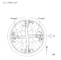
- FIG. 3 is a view showing a hybrid pole BLSRM suggested in the present invention.
- FIG. 4 is a view showing the hybrid structure of poles in the hybrid pole BLSRM according to the present invention.
- FIGS. 5 and 6 are views showing air-gap displacement in ⁇ - and ⁇ -directions and current state of axial windings in a stationary state and in an operation state at a constant rotational speed of 1,000 [rpm].
- the present invention suggests a BLSRM having a hybrid pole structure (hybrid pole BLSRM) capable of generating continuous torque and radial force.
- the hybrid pole BLSRM is designed such that a stator pole to generate torque is separated from a stator pole to generate suspending force for a rotor.
- a torque winding to generate torque and a winding to generate the suspending force for the rotor are separately mounted on the stator poles, respectively.
- pole-arc of the pole to generate the suspending force for the rotor is designed by taking into consideration a pole structure of the rotor.
- the pole-arc is designed such that poles are symmetrical to each other about an ⁇ -direction representing a horizontal axis and a ⁇ -direction representing a vertical axis.
- two ⁇ -directional windings generate suspending force moving the rotor to the left or rightside in a horizontal direction according to current applied to the two windings
- current flowing through ⁇ -directional pole windings generates suspending force moving the rotor to the up or down side in a vertical direction.
- Stator poles between two-directional suspending poles are designed to generate main torque.
- the torque is actually generated by reluctance between rotor and stator poles positioned between the suspending poles.
- the hybrid pole BLSRM according to the present invention makes less interaction between current generated from winding than that of a conventional BLSRM since the stator pole to generate the suspending force for the rotor is separated from the stator pole to generate torque.
- the hybrid pole BLSRM according to the present invention can generate continuous torque and radial force. In addition, the number of switching devices to drive a system can be reduced.
- FIG. 3 is a view showing the structure of the hybrid pole BLSRM suggested in the present invention
- FIG. 4 is a view showing a hybrid pole structure of the BLSRM according to the present invention.
- the hybrid pole BLSRM includes a stator provided with windings and a rotor rotating about a rotational axis as soon as current is conducted to the windings.
- the rotor has a plurality of rotor poles extending radially outward
- the stator has a plurality of stator poles extending radially inward.
- the windings include suspending windings (Sw) generating the suspending force of the rotor and torque windings (Tw) generating torque.
- the suspending windings (Sw) are mutually separated from the torque windings (Tw).
- stator poles PX 1 , PX 2 , PX 3 , and PX 4 represent radial force poles
- stator poles A 1 , A 2 , B 1 , and B 2 represent torque poles.
- the hybrid pole BLSRM has an 8/10 pole structure.
- the stator poles PX 1 and PX 3 relate to suspending windings (Sw) generating radial force in the ⁇ -direction
- the stator poles PX 2 and PX 4 relate to suspending windings (Sw) generating radial force in the ⁇ -direction.
- the stator poles A 1 and A 2 relate to torque windings (Tw) with an phase A
- the stator poles B 1 and B 2 relate to torque windings (Tw) with a phase B.
- the hybrid pole BLSRM according to the present invention is actually a 2-phase SRM to generate torque by current flowing through the torque windings (Tw) with the phases A and B.
- the suspending windings (Sw) related to the stator poles PX 1 , PX 2 , PX 3 , and PX 4 generate the radial force for the rotor.
- the suspending windings (Sw) generating the radial force for the rotor are mutually separated from the torque winding (Tw) generating the torque, the limitation of torque region in the conventional BLSRM can be overcome.
- the radial force for the rotor is generated through the interaction between the stator poles and the rotor poles. Therefore, in order to generate the continuous radial force for the rotor, the pole-arc (Pr) of the rotor must be considered.
- the hybrid pole BLSRM according to the present invention is designed such that the pole-arc (Ps) of the stator poles generating the radial force for the rotor becomes a pole pitch of the rotor shown in FIG. 4 by analyzing the interaction between the stator poles and the rotor poles.
- Ps pole-arc
- stator poles P x1 and P x3 serve as magnetic poles for radial force in the ⁇ -direction that represents a horizontal axis
- stator poles P x2 and P x4 serve as magnetic poles for radial force in the ⁇ -direction that represents a vertical axis.
- the stator poles P x1 and P x3 are symmetrical to each other
- the stator poles P x2 and P x4 are symmetrical to each other.
- an air-gap is formed between a rotor pole ⁇ r corresponding to the torque pole and a stator pole representing the radial force pole.
- the surficial areas of the radial force stator poles Px 1 , PX 2 , PX 3 , and PX 4 ( ⁇ sf) facing the rotor poles ⁇ r are greater than the surficial areas of the torque stator poles A 1 , A 2 , B 1 , and B 2 ( ⁇ st).
- FIGS. 5 and 6 are views showing the current state of axial windings and air-gap displacement in ⁇ - and ⁇ -directions when the hybrid pole BLSRM according to the present invention is in a stationary state with a load of 0.6 kgf, and operates at a constant rotational speed of 1,000 [rpm] with the load of 0.6 kgf.
Landscapes
- Engineering & Computer Science (AREA)
- Power Engineering (AREA)
- Synchronous Machinery (AREA)
- Magnetic Bearings And Hydrostatic Bearings (AREA)
- Connection Of Motors, Electrical Generators, Mechanical Devices, And The Like (AREA)
Abstract
Description
Claims (3)
Applications Claiming Priority (3)
| Application Number | Priority Date | Filing Date | Title |
|---|---|---|---|
| KR10-2009-0047080 | 2009-05-28 | ||
| KR1020090047080A KR101020994B1 (en) | 2009-05-28 | 2009-05-28 | Hybrid pole-less bearingless switched reluctance motor |
| PCT/KR2009/003844 WO2010137766A1 (en) | 2009-05-28 | 2009-07-14 | Hybrid pole bearingless srm |
Publications (2)
| Publication Number | Publication Date |
|---|---|
| US20120068558A1 US20120068558A1 (en) | 2012-03-22 |
| US9006948B2 true US9006948B2 (en) | 2015-04-14 |
Family
ID=43222862
Family Applications (1)
| Application Number | Title | Priority Date | Filing Date |
|---|---|---|---|
| US13/322,555 Expired - Fee Related US9006948B2 (en) | 2009-05-28 | 2009-07-14 | Hybrid pole bearingless SRM |
Country Status (3)
| Country | Link |
|---|---|
| US (1) | US9006948B2 (en) |
| KR (1) | KR101020994B1 (en) |
| WO (1) | WO2010137766A1 (en) |
Cited By (2)
| Publication number | Priority date | Publication date | Assignee | Title |
|---|---|---|---|---|
| US9831753B2 (en) * | 2016-04-14 | 2017-11-28 | Paul Boaventura-Delanoe | Switched reluctance permanent magnet motor |
| CN108494198A (en) * | 2018-03-29 | 2018-09-04 | 南京邮电大学 | A kind of simplex winding bearing-free switch reluctance motor and its control method |
Families Citing this family (28)
| Publication number | Priority date | Publication date | Assignee | Title |
|---|---|---|---|---|
| AT511480B1 (en) * | 2011-05-31 | 2014-02-15 | Johannes Kepler Uni Linz | ELECTRIC MACHINE WITH A MAGNETICALLY BASED RELAY TREADMILL |
| KR101306009B1 (en) * | 2011-08-16 | 2013-09-12 | 경성대학교 산학협력단 | 4/5 Two Phase SRM |
| CN102306995B (en) * | 2011-08-26 | 2013-08-28 | 北京航空航天大学 | Permanent magnet biased bearingless switched reluctance motor |
| CN102368657B (en) * | 2011-09-21 | 2014-02-12 | 江苏大学 | A bearingless brushless DC motor and its control method |
| AT513640B1 (en) * | 2012-12-04 | 2014-08-15 | Univ Wien Tech | Bearing and drive system |
| CN103199660A (en) * | 2013-04-08 | 2013-07-10 | 东南大学 | Stator permanent magnetic flux-switching bearing-free motor with E-shaped teeth |
| CN103236806B (en) * | 2013-05-06 | 2015-10-07 | 东南大学 | A kind of four pole type bearing-free switch reluctance motor |
| CN103296810B (en) * | 2013-05-10 | 2015-11-18 | 东南大学 | A kind of bearing-free formula half tooth is around switched reluctance machines |
| CN103825418A (en) * | 2013-12-31 | 2014-05-28 | 天津大学 | Single-winding non-bearing magnetic flux switching permanent magnetic motor |
| CN103780184B (en) * | 2014-01-17 | 2016-08-17 | 南京航空航天大学 | The Direct Torque of a kind of 12/8 pole simplex winding bearing-free switch reluctance motor and direct suspending power control method |
| CN103872811A (en) * | 2014-03-17 | 2014-06-18 | 东南大学 | Bearing-less stator surface mounting type permanent magnet motor for semi-tooth winding |
| CN103997176B (en) * | 2014-05-26 | 2016-08-31 | 江苏大学 | A kind of DC motor without bearing and brush and suspending power control method |
| CN104104197B (en) * | 2014-06-25 | 2016-09-14 | 南京邮电大学 | A kind of axial permanent magnetic offset hybrid magnetic bearing switched reluctance machines |
| WO2016127147A1 (en) * | 2015-02-06 | 2016-08-11 | Regents Of University Of Minnesota | Dual purpose no voltage winding design for bearingless ac homopolar and consequent pole motors and an ac homopolar flywheel energy storage system |
| EP3118976A1 (en) | 2015-07-17 | 2017-01-18 | Universite Catholique De Louvain | Electric machine having a radial electrodynamic bearing |
| KR101893262B1 (en) | 2016-11-04 | 2018-08-29 | 경성대학교 산학협력단 | Hybrid single-phase SRM with combined air gap |
| KR101893261B1 (en) | 2016-11-04 | 2018-08-30 | 경성대학교 산학협력단 | Hybrid single-phase SRM with non-uniform air gap |
| KR101893289B1 (en) | 2017-02-07 | 2018-08-29 | 경성대학교 산학협력단 | The Motor that prevent permanent magnet from coming off |
| CN106953580B (en) * | 2017-04-11 | 2019-02-26 | 南京埃克锐特机电科技有限公司 | A kind of power inverter of magnetic suspension switched reluctance motor |
| CN106992644B (en) * | 2017-04-26 | 2019-03-05 | 江苏大学 | A five-degree-of-freedom hybrid excitation magnetic levitation switched reluctance motor |
| EP3579390B1 (en) * | 2017-05-09 | 2024-08-28 | Daikin Industries, Ltd. | Turbo compressor |
| CN108123562B (en) * | 2017-12-19 | 2021-04-16 | 河北师范大学 | A bearingless permanent magnet synchronous motor |
| KR102036994B1 (en) | 2018-04-23 | 2019-10-25 | 경성대학교 산학협력단 | 2-phase Switched Reluctance Motor with step stator structure |
| CN108809030B (en) * | 2018-06-30 | 2019-12-31 | 淮阴工学院 | A Two-DOF Bearingless Switched Reluctance Motor Controlled by Outer Windings |
| CN109217594B (en) * | 2018-09-12 | 2020-05-22 | 北京航空航天大学 | A 12/10 Bearingless Permanent Magnet Bias Switched Reluctance Motor |
| KR102374803B1 (en) | 2019-12-19 | 2022-03-15 | 경성대학교 산학협력단 | Radial Force Reduction Switched Reluctance Motor |
| KR102300921B1 (en) | 2019-12-19 | 2021-09-09 | 경성대학교 산학협력단 | Improved Radial Force Reduction Switched Reluctance Motor |
| CN114400853B (en) * | 2022-02-21 | 2023-10-24 | 南京航空航天大学 | A bearingless switched reluctance motor |
Citations (5)
| Publication number | Priority date | Publication date | Assignee | Title |
|---|---|---|---|---|
| JPH08163847A (en) | 1994-11-30 | 1996-06-21 | Okuma Mach Works Ltd | Reluctance type resolver |
| US5880549A (en) * | 1995-03-30 | 1999-03-09 | Akira Chiba | Switched reluctance rotator |
| JP2000217394A (en) | 1999-01-25 | 2000-08-04 | Brother Ind Ltd | Stepping motor |
| KR20020046087A (en) | 2000-12-12 | 2002-06-20 | 구자홍 | Switched reluctance motor |
| US6727618B1 (en) * | 2002-06-10 | 2004-04-27 | The United States Of America, As Represented By The Administrator Of National Aeronautics And Space Administration | Bearingless switched reluctance motor |
-
2009
- 2009-05-28 KR KR1020090047080A patent/KR101020994B1/en not_active Expired - Fee Related
- 2009-07-14 WO PCT/KR2009/003844 patent/WO2010137766A1/en not_active Ceased
- 2009-07-14 US US13/322,555 patent/US9006948B2/en not_active Expired - Fee Related
Patent Citations (5)
| Publication number | Priority date | Publication date | Assignee | Title |
|---|---|---|---|---|
| JPH08163847A (en) | 1994-11-30 | 1996-06-21 | Okuma Mach Works Ltd | Reluctance type resolver |
| US5880549A (en) * | 1995-03-30 | 1999-03-09 | Akira Chiba | Switched reluctance rotator |
| JP2000217394A (en) | 1999-01-25 | 2000-08-04 | Brother Ind Ltd | Stepping motor |
| KR20020046087A (en) | 2000-12-12 | 2002-06-20 | 구자홍 | Switched reluctance motor |
| US6727618B1 (en) * | 2002-06-10 | 2004-04-27 | The United States Of America, As Represented By The Administrator Of National Aeronautics And Space Administration | Bearingless switched reluctance motor |
Cited By (2)
| Publication number | Priority date | Publication date | Assignee | Title |
|---|---|---|---|---|
| US9831753B2 (en) * | 2016-04-14 | 2017-11-28 | Paul Boaventura-Delanoe | Switched reluctance permanent magnet motor |
| CN108494198A (en) * | 2018-03-29 | 2018-09-04 | 南京邮电大学 | A kind of simplex winding bearing-free switch reluctance motor and its control method |
Also Published As
| Publication number | Publication date |
|---|---|
| US20120068558A1 (en) | 2012-03-22 |
| KR101020994B1 (en) | 2011-03-09 |
| KR20100128594A (en) | 2010-12-08 |
| WO2010137766A1 (en) | 2010-12-02 |
Similar Documents
| Publication | Publication Date | Title |
|---|---|---|
| US9006948B2 (en) | Hybrid pole bearingless SRM | |
| EP2945266B1 (en) | Double stator switched reluctance rotating machine | |
| US10756607B2 (en) | Motor and rotor | |
| CA2613394C (en) | Direct drive for large-scale drives | |
| JP5375858B2 (en) | Variable field rotating electric machine | |
| EP3128658B1 (en) | Double-stator switched reluctance dynamo | |
| US8390165B2 (en) | Synchronous motor drive system | |
| EP2226924A1 (en) | Motor and rotor for dynamo-electric machine | |
| JP2003009486A (en) | Variable speed motor | |
| Matyska | Advantages of synchronous reluctance motors | |
| US9876456B2 (en) | Brushless electrical machine | |
| JP5301905B2 (en) | Multi-phase rotating electrical machine drive device, multi-phase generator converter, multi-phase rotating electrical machine, and rotating electrical machine drive system | |
| JP5885423B2 (en) | Permanent magnet rotating electric machine | |
| JP2010161832A (en) | Permanent magnet rotating electrical machine | |
| JP6376409B2 (en) | AC excitation synchronous rotating electric machine | |
| CN110431727A (en) | Electric motor with a converter element in the magnetic circuit | |
| US10608489B2 (en) | Switched reluctance machine with rotor excitation using permanent magnets | |
| Noguchi et al. | Combined winding structure of a consequent-pole bearingless motor with parallel motor winding topology | |
| US20090072649A1 (en) | Brushless electric motor | |
| JP2002325476A (en) | Motor device | |
| US10601350B2 (en) | Motor device, motor driving control device and motor driving method | |
| Xu et al. | Hybrid pole type bearingless switched reluctance motor with short flux path | |
| CN111293805A (en) | Electric machine | |
| JP3840715B2 (en) | Permanent magnet synchronous motor | |
| JP2016197941A (en) | Rotating electric machine |
Legal Events
| Date | Code | Title | Description |
|---|---|---|---|
| AS | Assignment |
Owner name: KYUNGSUNG UNIVERSITY INDUSTRY COOPERATION, KOREA, Free format text: ASSIGNMENT OF ASSIGNORS INTEREST;ASSIGNORS:AHN, JIN WOO;LEE, DONG HEE;WANG, HUIJUN;REEL/FRAME:027285/0447 Effective date: 20111116 |
|
| STCF | Information on status: patent grant |
Free format text: PATENTED CASE |
|
| AS | Assignment |
Owner name: KYUNGSUNG UNIVERSITY INDUSTRY COOPERATION FOUNDATI Free format text: CORRECTIVE ASSIGNMENT TO CORRECT THE ASSIGNEE NAME PREVIOUSLY RECORDED AT REEL: 027285 FRAME: 0447. ASSIGNOR(S) HEREBY CONFIRMS THE ASSIGNMENT;ASSIGNORS:AHN, JIN WOO;LEE, DONG HEE;WANG, HUIJUN;REEL/FRAME:036700/0809 Effective date: 20111116 |
|
| MAFP | Maintenance fee payment |
Free format text: PAYMENT OF MAINTENANCE FEE, 4TH YR, SMALL ENTITY (ORIGINAL EVENT CODE: M2551); ENTITY STATUS OF PATENT OWNER: SMALL ENTITY Year of fee payment: 4 |
|
| FEPP | Fee payment procedure |
Free format text: MAINTENANCE FEE REMINDER MAILED (ORIGINAL EVENT CODE: REM.); ENTITY STATUS OF PATENT OWNER: SMALL ENTITY |
|
| LAPS | Lapse for failure to pay maintenance fees |
Free format text: PATENT EXPIRED FOR FAILURE TO PAY MAINTENANCE FEES (ORIGINAL EVENT CODE: EXP.); ENTITY STATUS OF PATENT OWNER: SMALL ENTITY |
|
| STCH | Information on status: patent discontinuation |
Free format text: PATENT EXPIRED DUE TO NONPAYMENT OF MAINTENANCE FEES UNDER 37 CFR 1.362 |
|
| FP | Lapsed due to failure to pay maintenance fee |
Effective date: 20230414 |