US5880549A - Switched reluctance rotator - Google Patents
Switched reluctance rotator Download PDFInfo
- Publication number
- US5880549A US5880549A US08/750,167 US75016797A US5880549A US 5880549 A US5880549 A US 5880549A US 75016797 A US75016797 A US 75016797A US 5880549 A US5880549 A US 5880549A
- Authority
- US
- United States
- Prior art keywords
- winding
- current
- current terminal
- electrically connected
- protruding
- Prior art date
- Legal status (The legal status is an assumption and is not a legal conclusion. Google has not performed a legal analysis and makes no representation as to the accuracy of the status listed.)
- Expired - Fee Related
Links
- 238000004804 winding Methods 0.000 claims abstract description 509
- 230000004907 flux Effects 0.000 claims description 52
- 239000013598 vector Substances 0.000 claims description 34
- 238000001514 detection method Methods 0.000 claims description 11
- 238000000034 method Methods 0.000 description 29
- 238000010586 diagram Methods 0.000 description 19
- 238000010276 construction Methods 0.000 description 8
- XEEYBQQBJWHFJM-UHFFFAOYSA-N Iron Chemical group [Fe] XEEYBQQBJWHFJM-UHFFFAOYSA-N 0.000 description 6
- 230000001965 increasing effect Effects 0.000 description 5
- 230000008901 benefit Effects 0.000 description 4
- 230000007423 decrease Effects 0.000 description 4
- 230000003247 decreasing effect Effects 0.000 description 3
- 230000000694 effects Effects 0.000 description 3
- 230000003321 amplification Effects 0.000 description 2
- 238000013459 approach Methods 0.000 description 2
- 229910052742 iron Inorganic materials 0.000 description 2
- 238000003199 nucleic acid amplification method Methods 0.000 description 2
- 241001233242 Lontra Species 0.000 description 1
- 230000009471 action Effects 0.000 description 1
- 230000008859 change Effects 0.000 description 1
- 230000001939 inductive effect Effects 0.000 description 1
- 230000003993 interaction Effects 0.000 description 1
- 238000003754 machining Methods 0.000 description 1
- 230000002093 peripheral effect Effects 0.000 description 1
- 230000004044 response Effects 0.000 description 1
- 230000000630 rising effect Effects 0.000 description 1
- 239000004065 semiconductor Substances 0.000 description 1
- 238000006467 substitution reaction Methods 0.000 description 1
Images


Classifications
-
- H—ELECTRICITY
- H02—GENERATION; CONVERSION OR DISTRIBUTION OF ELECTRIC POWER
- H02P—CONTROL OR REGULATION OF ELECTRIC MOTORS, ELECTRIC GENERATORS OR DYNAMO-ELECTRIC CONVERTERS; CONTROLLING TRANSFORMERS, REACTORS OR CHOKE COILS
- H02P25/00—Arrangements or methods for the control of AC motors characterised by the kind of AC motor or by structural details
- H02P25/02—Arrangements or methods for the control of AC motors characterised by the kind of AC motor or by structural details characterised by the kind of motor
- H02P25/08—Reluctance motors
-
- F—MECHANICAL ENGINEERING; LIGHTING; HEATING; WEAPONS; BLASTING
- F16—ENGINEERING ELEMENTS AND UNITS; GENERAL MEASURES FOR PRODUCING AND MAINTAINING EFFECTIVE FUNCTIONING OF MACHINES OR INSTALLATIONS; THERMAL INSULATION IN GENERAL
- F16C—SHAFTS; FLEXIBLE SHAFTS; ELEMENTS OR CRANKSHAFT MECHANISMS; ROTARY BODIES OTHER THAN GEARING ELEMENTS; BEARINGS
- F16C32/00—Bearings not otherwise provided for
- F16C32/04—Bearings not otherwise provided for using magnetic or electric supporting means
- F16C32/0406—Magnetic bearings
- F16C32/044—Active magnetic bearings
- F16C32/0444—Details of devices to control the actuation of the electromagnets
-
- F—MECHANICAL ENGINEERING; LIGHTING; HEATING; WEAPONS; BLASTING
- F16—ENGINEERING ELEMENTS AND UNITS; GENERAL MEASURES FOR PRODUCING AND MAINTAINING EFFECTIVE FUNCTIONING OF MACHINES OR INSTALLATIONS; THERMAL INSULATION IN GENERAL
- F16C—SHAFTS; FLEXIBLE SHAFTS; ELEMENTS OR CRANKSHAFT MECHANISMS; ROTARY BODIES OTHER THAN GEARING ELEMENTS; BEARINGS
- F16C32/00—Bearings not otherwise provided for
- F16C32/04—Bearings not otherwise provided for using magnetic or electric supporting means
- F16C32/0406—Magnetic bearings
- F16C32/044—Active magnetic bearings
- F16C32/0474—Active magnetic bearings for rotary movement
- F16C32/0493—Active magnetic bearings for rotary movement integrated in an electrodynamic machine, e.g. self-bearing motor
- F16C32/0497—Active magnetic bearings for rotary movement integrated in an electrodynamic machine, e.g. self-bearing motor generating torque and radial force
-
- H—ELECTRICITY
- H02—GENERATION; CONVERSION OR DISTRIBUTION OF ELECTRIC POWER
- H02K—DYNAMO-ELECTRIC MACHINES
- H02K19/00—Synchronous motors or generators
- H02K19/02—Synchronous motors
- H02K19/10—Synchronous motors for multi-phase current
- H02K19/103—Motors having windings on the stator and a variable reluctance soft-iron rotor without windings
-
- H—ELECTRICITY
- H02—GENERATION; CONVERSION OR DISTRIBUTION OF ELECTRIC POWER
- H02K—DYNAMO-ELECTRIC MACHINES
- H02K7/00—Arrangements for handling mechanical energy structurally associated with dynamo-electric machines, e.g. structural association with mechanical driving motors or auxiliary dynamo-electric machines
- H02K7/08—Structural association with bearings
- H02K7/09—Structural association with bearings with magnetic bearings
-
- H—ELECTRICITY
- H02—GENERATION; CONVERSION OR DISTRIBUTION OF ELECTRIC POWER
- H02K—DYNAMO-ELECTRIC MACHINES
- H02K3/00—Details of windings
- H02K3/04—Windings characterised by the conductor shape, form or construction, e.g. with bar conductors
- H02K3/28—Layout of windings or of connections between windings
Definitions
- This invention relates to a switched reluctance rotator. More particularly, it relates to a switched reluctance rotator capable of rotating a rotor at a high speed without generating electromagnetic vibration at the rotating shaft of the rotor.
- a switched reluctance rotator includes a switched reluctance motor and a switched reluctance generator.
- a conventional switched reluctance motor is shown in FIG. 32.
- switched reluctance motor 50 comprises a four pole rotor 51 wherein each of the poles protrudes crosswisely around the rotating shaft and a six pole stator 52 arranged around the rotor 51, each of the protruding pole of said stator 52 having a concentrated winding 53 which is concentratedly wound.
- the current passed through winding 53 (referred to as a winding current) is unidirectional and includes a distorted wave current and direct current component.
- 54 indicates an invertor and 55 indicates a direct current source.
- the protruding poles of stator 52 attract the protruding poles on the outer peripheral surface of rotor 51 to generate a torque and as a result, rotor 51 rotates.
- the rotor 51 is eccentric or machined incorrectly a great force in the radial direction is generated, which generates an electromagnetic vibration.
- the length of gap between the rotor 51 and the stator 52 is extremely reduced for improving the efficiency of said rotator, another problem occurs that more electromagnetic vibration and more noise are generated compared with a usual motor.
- An object of this invention is to solve the above problems. Another object of this invention is to provide a switched reluctance rotator according to which even if deviation of the rotating shaft occurs when the rotor is rotating, the deviation is automatically corrected to prevent from the generation of electromagnetic vibration and simultaneously the rotor is supported in a levitating manner by a magnetic force, and thus, the rotating shaft rotates smoothly.
- This invention relates to a switched reluctance rotator, characterized by having a rotor provided with a plurality of protruding poles, a stator arranged around the rotor and provided with protruding poles, windings provided at the respective protruding poles of the stator, and a current controlling part which controls the current passed through the windings so as to generate a torque and a radial force at the rotor.
- the windings are independently on the respective protruding poles so that said windings can be independently energized, and said current controlling device is formed so that the current passed through the respective windings can be independently controlled so as to generate a radial force.
- the windings comprise a plurality of groups of windings through which current can be independently passed and said current controlling device is formed so that the current passed through said winding groups can be independently controlled so as to generate a radial force.
- Another invention relates to a switched reluctance rotator having a rotor provided with a plurality of protruding poles, a stator arranged around the rotor and provided with protruding poles, and windings for generating a torque provided at the respective protruding poles of the stator and generating a rotating torque at the rotor, characterized in that the windings for generating radial force which give a radial force to the rotor are provided at the respective protruding poles of the rotor so as to magnetically levitate the rotor.
- This switched reluctance rotator desirably has a deviation detector which detects the deviation of the rotor in the radial direction and a current controlling part which inputs therein the detection signal which is the output from the deviation detector and outputs a controlled current to the windings for generating a radial force.
- FIG. 1 is a diagram explaining the principle of generating a torque at the rotor in a switched reluctance rotator of this invention.
- FIGS. 2-4 are diagrams explaining the first method for generating a radial force at the rotor in a switched reluctance rotator of this invention.
- FIGS. 5-7 are diagrams explaining the second method for generating a radial force at the rotor in a switched reluctance rotator of this invention.
- FIGS. 8-10 are diagrams explaining the third method for generating a radial force at the rotor in a switched reluctance rotator of this invention.
- FIGS. 11-13 are diagrams explaining the fourth method for generating a radial force at the rotor in a switched reluctance rotator of this invention.
- FIG. 14 is a graph which shows the relations between rotating angle and inductance, current and interlinkage number of magnetic fluxes in the windings for generating a radial force which are wound on the protruding poles of the stator in a switched reluctance rotator of this invention.
- FIG. 15 is a graph which shows the relation between the current passed through the windings for generating a radial force and the interlinkage number of magnetic fluxes.
- FIG. 16 is a diagram explaining that the radial force is proportional to the difference between the square of magnetic flux densities B + and B - of poles opposite to each other.
- FIG. 17 is a block diagram showing three systems for determining the quantity of current passed through the windings for generating a radial force.
- FIG. 18 is a diagram showing an estimation circuit which estimates the interlinkage number of magnetic flux ⁇ from the current i.
- FIG. 19 is a graph showing the relation between the current value passed through the windings for generating a radial force and the magnetic flux interlinkage number.
- FIG. 20 is a block diagram showing a method for determining the current instruction value necessary for generating a radial force from a data which show the position of the rotating shaft in a radial direction.
- FIGS. 21-22 are diagrams explaining the fifth method for generating a radial force at the rotor in a switched reluctance rotator of this invention.
- FIGS. 23-24 are diagrams explaining another example of the fifth method for generating a radial force at the rotor in a switched reluctance rotator of this invention.
- FIG. 25 is a diagram explaining the sixth method included in the second method for generating a radial force.
- FIGS. 26-27 are diagrams explaining another example of the seventh method for generating a radial force at the rotor in a switched reluctance rotator of this invention.
- FIG. 28 is a diagram schematically explaining one example of this invention.
- FIG. 29 is a diagram schematically explaining another example of this invention.
- FIG. 30 is a diagram schematically showing the rotor and the stator in a switched reluctance motor shown in FIG. 29.
- FIG. 31 is a diagram schematically explaining further another example of this invention.
- FIG. 32 is a schematic diagram of a conventional general switched reluctance motor.
- the switched reluctance rotator of this invention has a rotor provided with a plurality of protruding poles, a stator arranged around the rotor and provided with a plurality of protruding poles facing the rotor, and windings wound on the protruding poles of the stator.
- the number of the protruding poles provided on the rotor differs from that of the protruding poles provided on the stator.
- protruding poles of the stator and the rotor are formed so that not all of the protruding poles of the stator face to the protruding poles of the rotor when the rotor is standing still, there is no limitation both in the number of the protruding poles of the stator and the number of the protruding poles of the rotor.
- the number of the protruding poles of the stator is even. With increase in the number of the protruding poles of the stator and the rotor, the rotor rotates more smoothly.
- the rotor of this switched reluctance rotator generates a torque after the following principle.
- the switched reluctance rotator shown in FIG. 1 is taken as an example.
- the switched reluctance rotator has a stator 2 with six protruding poles 1 and a rotor 4 with four protruding poles 3.
- Each of protruding poles 1 on stator 2 is wound with winding 5, and the windings 5 on the two protruding poles 1 opposite to each other are electrically connected.
- three pairs of opposite two poles of phase A, phase B, and phase C are formed.
- protruding poles 1 of phase B are magnetized and attract protruding poles 3 of the rotor to generate a clockwise torque.
- a torque is generated at the rotor by successively energizing the adjacent winding according to the position of protruding pole 3 of the rotor.
- " ⁇ " and “X” ⁇ in denoting the winding indicate the direction of passing current
- “ ⁇ ” indicates the direction of the current piercing through the paper from the reverse side to the face of the paper
- "X” indicates the direction of the current piercing, through the paper from the face thereof to the reverse side.
- the rotor When the rotor is rotated at a low speed, it is preferred to pass a current having a rectangular wave form of nearly constant current peak value through the, windings, and, furthermore, when load applied to the rotor is small, preferably the period of passing the above rectangular wave current is shortened or the height of the above current wave is lowered.
- the switched reluctance rotator of this invention deviation of the rotor can be avoided and the rotor can be magnetically levitated by applying a radial force to the rotor according to the deviation data output from a means which detects the deviation of the rotor from the rotation center.
- the first method comprises passing a current for generating a torque through each of the windings on the protruding pole of the stator and passing a controlled current through the windings so as to generate a radial force at the rotor.
- This first method is advantageous in that a large invertor is not specifically needed for generating a torque at the rotating shaft of the switched reluctance rotator since a strong radial force can be generated by this method. Therefore, a switched reluctance rotator employing this method is suitable in case when not a large torque generated at the rotating shaft but a large radial force is needed.
- the first method further includes several systems.
- One example of the first system is such that twelve protruding poles are provided on the stator and each of the protruding poles has a winding, and, on the other hand, eight protruding poles are provided on the rotor, wherein the currents passed through the windings are independently controlled so as to generate a radial force.
- F AY for generating Y-direction force F AY , the current passed through the A y + winding 5 on the protruding pole 1 of the stator 2 is increased and the current passed through the A y - winding 5 on the protruding pole 1 opposite to the protruding pole 1 wound with the A y + winding 5 is decreased,
- An X-direction force F AX also can be similarly generated.
- a radial force of any direction can be generated by combining the above three radial forces according to the magnetic flux number generated at each of the protruding poles 1 of the stator 2.
- the first system requires twenty-four wirings for the windings on the twelve protruding poles, and a controller for independently controlling the current passed through the twelve windings such as a 12-phase invertor is necessary.
- radial forces can be generated in any direction by passing the current independently through the winding wires on an arbitrary number of protruding poles provided on the stator and controlling the quantity of the passing current.
- an example of the second system is such that twelve protruding poles 1 are provided at the stator 2 and each of the protruding poles 1 is wound with winding 5, further, eight protruding poles 3 are provided at the rotor 4, wherein currents of different current value are passed through windings 5 on two protruding poles 1 one of which is in the direction perpendicular to the direction of another and windings. 5 on the two protruding poles 1 opposite to the above two protruding poles 1.
- a radial force Fb is generated by passing current i b1 and current i b2 (i b1 >i b2 )
- a radial force F c is generated by passing current i c1 and current i c2 (i c1 >i c2 )
- Radial force of desired direction and strength is generated by combining the forces of these three directions.
- the first method for generating a radial force at the rotor is a system of passing a current controlled to generate a radial force through the winding which generates a torque, and, accordingly, the winding for generating torque and the winding for generating radial force-.-are the same.
- the second method for generating a radial force at the rotor in this invention is to provide, in addition to a winding for generating torque at the protruding poles of the stator (sometimes referred to as “torque generating winding"), another winding for generating radial force (sometimes referred to as “differential winding” or “radial force generating winding”).
- torque generating winding a winding for generating torque at the protruding poles of the stator
- another winding for generating radial force sometimes referred to as “differential winding” or "radial force generating winding”
- the switched reluctance rotator which employs the second method in which the magnetic flux generated by the torque generating winding and the magnetic flux generated by the differential winding are imbalanced by applying the differential winding is suitable for bearing-less rotator's which are mainly intended to generate torque.
- This second method can :further be classified into several systems.
- the third system (since the systems included in the first method are called the first system and the second system, consecutive numbers will be employed hereinafter), as shown in FIG. 8 to FIG. 10, in the switched reluctance rotator in which twelve protruding poles 1 are provided at the stator 2 and each of protruding poles 1 is wound with torque generating winding 6 and eight protruding poles 3 are provided at the rotor 4, the winding on one protruding pole 1 of the stator 2 is connected in series with the winding on another protruding pole opposite to the above protruding pole, thereby to form six pairs of radial force generating windings 7a.
- each of the twelve protruding poles 1 is wound with torque generating winding 6 and radial force generating winding 7, and torque generating windings 6A on protruding poles 1A of phase A are connected in series with each other, and, similarly, torque generating windings 6B on protruding poles 1B of phase B and torque generating windings 6C wound on protruding poles 1C of phase C are also connected in series with each other, respectively.
- two radial force generating windings 7A which are in the positions perpendicular to each other are wound so that the current flows in the same direction as the direction of the current in the torque generating winding 6A on the protruding pole 1A, and two radial force generating windings 7A opposite to the above-mentioned two radial force generating windings 7A are wound so that the current flows in the direction opposite to the direction of the current in the torque generating winding 6A on the protruding pole 1A, and, besides, four radial force generating windings 7A are connected in series so that the direction of the current is as mentioned in the above. Because the radial-force or differential windings are wound in the same sense of rotation their magnetic fields are aligned instead of opposite.
- a radial force in the direction of Fb is generated by flowing current i b into radial force generating windings 7B
- a radial force in the direction of Fc is generated by flowing current i c into the radial force generating windings 7C. Therefore, by controlling the currents i a , i b and i c , radial forces of any directions can be generated as a combination of the radial forces of three directions.
- a radial force of a given direction is generated as a combination of radial forces of three or six directions. Since if radial forces of at least two directions can be generated, a desired amount radial force can be generated, it appears simple to generate a radial force of three directions or six directions.
- FIG. 14 shows the relations between the rotating angle of the rotor and the increase or decrease of inductance, the current supplied to the torque generating winding (i.e., motor driving current) and the interlinkage number of magnetic flux in the phase A.
- FIG. 14 shows the relation between the interlinkage number of magnetic flux and the current.
- a current is passed through the torque generating winding at about the rising of inductance to generate a torque of the rotor.
- FIG. 15 shows the relation between the current passed through the radial force generating winding and the interlinkage number of magnetic flux.
- the radial force is in proportion to the difference between the square of magnetic flux density B + and the square of magnetic flux density B of the poles opposite to each otter. Therefore, when the interlinkage number of magnetic flux is large, a large radial force can be generated by passing a small current through the radial force generating winding. Thus, by imbalancing the magnetic flux density of the poles in the section of the larger interlinkage number of magnetic flux, a radial force can be efficiently generated.
- sections of phase A to phase C having a large interlinkage number of magnetic flux C should be as wide as possible.
- the magnetic flux interlinkage number is always kept large in one phase in the first and the third systems and in two phases in the second and the fourth systems.
- the radial force F is shown by the following formula (1) in the model shown in FIG. 16.
- S indicates an area at the gap between the protruding pole of the rotor and that of the stator
- ⁇ 0 is 4 ⁇ 10 -7 H/mr
- B + and B - indicate magnetic flux density.
- N indicates the winding number of the winding.
- the magnetic flux interlinkage number of the upper winding is indicated by ⁇ +
- the magnetic flux interlinkage number of the lower winding is indicated by ⁇ -
- the winding number is indicated by N
- the current can be determined by the system 1 shown in FIG. 17.
- i A * is a current instruction value for generating a torque at the rotor and F * is a current instruction value for generating radial force.
- F * is a current instruction value for generating radial force.
- the above formula (4) is solved on i to obtain the result of i S * , which is added to i A * to obtain i aY + .
- i S * is subtracted from i A * to obtain i aY - .
- Current i aY + is passed through A y + winding shown in FIG. 2 and current i aY - is passed through A y - winding.
- i A * is the differential winding current.
- This formula may be solved to obtain is from (i + 2 -i - 2 ). Therefore, the calculation of i ay +2 -i ay -2 may be omitted.
- i ay + and i ay - may be detected with the output of controller of i S and without changing the form of the controller in the system 2.
- the output of controller is preferably i S .
- i A * may be a detected value and i S * may also be a detected value.
- i aY + and i aY - correspond to i a1 and i a2 in the systems 1-3 in FIG. 17, respectively.
- the fourth system is similar to the third system.
- i A * when i A * is 0 or small, i, i S * , i A * increase, respectively.
- i S and i are restricted to around i A * >(i S * or i). That is, it occurs that i S * or i is close to i A * when F * is larger than the radial force which can be generated at the pole or phase. In this case, the magnetic flux level must be increased by transmitting a signal to the controller of the rotator.
- the data on the position in radial direction are input into the radial direction position controller 10 from a detector (deviation detector) which detects the position of rotating shaft in X direction and Y direction, this radial position controller 10 determines radial force instruction values F ⁇ * and F ⁇ * , and these radial force instruction values F ⁇ * and F ⁇ * are output to the radial force vector distributor 11, where the desired radial force is resolved into vectors.
- a detector device detector
- the rotator controller 12 When the magnetic flux level is insufficient, demand for increasing of magnetic flux level is sent to rotator controller 12.
- the rotator controller 12 receiving the demand generates and outputs current instruction values i A * , i B * and i C * which increase the magnetic flux level without changing torque portion.
- the current instruction values i A * , i B * and i C * and the radial forces F a * , F b * and F c * of three directions output from the radial force vector distributor 11 are output to the radial force controller 13 containing either one of the systems 1-3 shown in FIG.
- speed controller 15 inputs therein the detected speed data output from the speed detector which. detects the rotation speed of the rotor and determines the torque for rotating said rotor in a given rotation speed and outputs torque instruction value. Furthermore, invertor ON/OFF commander 14 inputs therein the current instruction values i A * , i B * and i C * output from the rotator controller 12 and send a signal to instructing ON/OFF switching to the invertor.
- MMF or magnetic flux by which the current which is passed through the radial force generating winding can be generated is previously calculated, and current instructions can be generated at the rotator so that the magnetic flux level is not smaller than the calculated magnetic flux.
- this method is effective. According to this method, the demand for increase of magnetic level is not necessary. This method is equivalent previously to controlling the rotator so that the magnetic level does not increase.
- all the protruding poles of the stator are grouped into four groups, and the protruding poles belonging to one of the four groups and the protruding poles belonging to another group in the position opposite to the above protruding poles are wound in a concentrated manner.
- twelve protruding poles 1 formed at the stator 2 are grouped into four groups, each of which contains adjacent three protruding poles 1, and given three protruding poles 1 and three protruding poles 1 opposite to the above three protruding poles 1 are wound in concentrated manner with windings.
- the protruding poles 1 opposite to each other are wound in a concentrated manner with windings.
- six radial force generating windings 1-6 are formed and twelve wirings are needed. Independently controlled current is passed through each of the radial force generating windings 1-6.
- the direction of the passed current is the same as the direction of the winding in FIG. 21 and FIG. 22.
- a radial force in a desired direction is generated as a vectorial sum of the radial forces generated by the radial force generating windings 1-6. Since concentrated windings are used as the above radial force generating windings, a radial force can be generated accurately and efficiently by calculating the radial direction vector in accordance with a momentary value of the current passing through each of the radial force generating windings 1-6.
- the method for the concentrated winding is as follows: as shown in FIG. 23 and FIG. 24, the windings on the adjacent three protruding poles are connected in series with each other to form two radial force generating windings 1 and 2.
- This concentrated winding has the advantage that four wiring suffice to generate the radial force F.
- radial force generating windings 6 of distributed winding are wound at slot 8 between the protruding poles 1 of the stator 2 and at slot 8 opposite to the above slot 8, and radial force generating windings 6 of distributed winding in the direction perpendicular to the above radial force generating windings 6 are wound at slot 8 and at slot 8 opposite to the said slot 8.
- first radial force generating windings which are distributed windings are placed in a slot between any of protruding poles and in the slot opposite to the said slot of the stator having a plurality of protruding poles on the inside thereof, and second radial force generating windings which are distributed windings are placed in a pair of slots which are positioned perpendicular to the pair of slots utilized for forming the first radial force generating windings and are positioned opposite to each other.
- two radial force generating windings 6 are provided, and as shown, for example, in FIG. 25, a current of i X +i y is passed through one of the two radial force generating windings 6 and a current of i X -i y is passed through another radial force generating winding 6.
- the radial force F X in the direction of X axis is in proportion to the current i X and the radial force F y in the direction of Y axis is in proportion to the current i y .
- a protruding pole and another protruding pole opposite to the said protruding pole are selected, and the first radial force generating windings which are distributed winding are provided at a pair of slots on one side of the above-mentioned pair of protruding poles of the stator having a plurality of protruding poles on the inside thereof; second radial force generating windings which are distributed winding are provided at a pair of slots on another side of the above-mentioned pair of the protruding poles; third radial force generating windings which are distributed winding are provided at a pair of slots on one side of a pair of protruding poles which are positioned perpendicular to the poles utilized for forming the first and second radial force generating windings and are opposite to each other; and fourth radial force generating windings which are distributed winding are provided at a pair of slots on another side of the above-mentioned pair of the
- the first to fourth radial force generating windings 1-4 are wound in the following manner. That is, for example, as shown in FIG. 26, the first radial force generating winding 1 is placed as a distributed winding at a pair of slots 8 located in the right side of stator 2, said slots 8 being located adjacent to two protruding poles 1 selected from twelve protruding poles 1 on stator 2. One of the two protruding poles 1 is in Y direction and another is opposite thereto.
- the second radial force generating winging 2 is provided so that it is adjacent to the first radial force generating winding 1.
- the second radial force generating winging 2 is wound as a distributed winding at a pair of slots 8 which are positioned on the opposite side to the pair of slots where the first radial force generating winding 1 is wound, with the said pair of the protruding poles 1, 1 therebetween.
- a current in the same direction is passed through the first radial force generating winding 1 and the second radial force generating winging 2.
- the third radial force generating winding 3 is placed as a distributed at a pair of slots located in the upper side of stator 2, said slots 8 being located adjacent to two opposite protruding poles 1, 1 which are in X direction and perpendicular to the protruding poles 1, 1 used for forming said first radial force generating winding 1.
- the fourth radial force generation winging 4 is provided so that it is adjacent to the third radial force generating winding 3.
- This fourth radial force generating winging 4 is wound as a distributed winding at a pair of slots 8 which are positioned on the opposite side to the pair of slots where the third radial force generating winding 3 is wound, with the said pair of the protruding poles 1, 1 therebetween.
- a current in the same direction is passed through the third radial force generating winding 3 and the fourth radial force generating winging 4.
- FIG. 28 is a diagram schematically explaining a switched reluctance motor exemplifying this invention.
- this switched reluctance motor 21 has rotor 22 having four protruding poles arranged in the directions perpendicular to each other and stator 23 having six protruding poles arranged at central angles of 60° to each other.
- Rotating shaft 20 is pierced through the center of rotor 22.
- the torque generating winding 24 on the first protruding pole 23a is connected with the torque generating winding 24 on the fourth protruding pole 23d which is arranged opposite to the first protruding pole 23a, and another end of the torque generating winding 24 on the first protruding pole 23a and another end of the torque generating winding 24 on the fourth protruding pole 23d are connected with the electric source.
- the torque generating winding 24 on the second protruding pole 23b is connected with the torque generating winding 24 on the fifth protruding pole 23e which is arranged opposite to the second protruding pole 23b, and another end of the torque generating winding 24 on the second protruding pole 23b and another end of the torque generating winding 24 on the fifth protruding pole 23e are connected with the electric source.
- the torque generating winding 24 on the third protruding pole 23c is connected with the torque generating winding 24 on the sixth protruding pole 23f which is arranged opposite to the third protruding pole 23c, and another end of the torque generating winding 24 on the third protruding pole 23c and another end of the torque generating winding 24 on the sixth protruding pole 23f are connected with the electric source.
- the radial force generating winding 25 on the first protruding pole 23a and the radial force generating winding 25 on the fourth protruding pole 23d arranged opposite to the first protruding pole 23a are connected in series.
- the radial force generating winding 25 on the second protruding pole 23b and the radial force generating winding 25 on the fifth protruding pole 23e arranged opposite to the second protruding pole 23b are connected in series.
- the radial force generating winding 25 on the third protruding pole 23c and the radial force generating winding 25 on the sixth protruding pole 23f arranged opposite to the third protruding pole 23c are connected in series.
- the electric source 26 is formed so that a distorted wave current including a direct current can be supplied to the above-mentioned torque generating winding 24.
- the electric source 26 is formed of direct current source 26a and invertor 26b. This invertor 26b generates a distorted three phase current wherein each of the phase differs by 30°.
- the switched reluctance motor 21 of the above construction works in the following manner.
- a rotating magnetic field is generated at the stator 23 by passing the distorted three phases current from the invertor 26b through windings 24, and the rotor 22 is rotated.
- the motor illustrated in this example has the following features or advantages: (1) The main shaft can be supported magnetically in a radial direction; (2) The voltage and current applied to the radial force generating winding 25 can be small; and others.
- the above relation between the number of the protruding poles of the rotor and the number of the protruding poles of the stator can apply to the whole of this invention including the following Examples 2 and 3.
- the shaft can be supported magnetically at a specific rotation speed by using a short circuit without an invertor connected to a radial force generating winding or by using a passive device circuit.
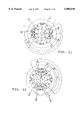
- FIG. 29 shows a switched reluctance motor which is another example of this invention (hereinafter referred to as merely "motor").
- the same reference numerals as in FIG. 28 are used for the members having the same functions as in FIG. 28.
- this switched reluctance motor 21a has a rotor 22 provided with four protruding poles arranged in the direction perpendicular to each other, a stator 23 provided with six protruding poles arranged so that they are at central angles of 60° to each other, two deviation detecting sensors 27a, 27b, electric sources 28a, 28b, and a controller 29.
- a rotating shaft is pierced through the center of the rotor 22.
- the six protruding poles of stator 23 are arranged so that two of them are opposed to each other.
- Each protruding poles of stator 23 is wound with torque generating winding 24 and with radial force generating winding 25.
- the direction of the current passed through the torque generating winding 24 and wire connections thereof are the same as in Example 1, but the end of the torque generating winding 24 is connected to invertor 28a for the switched reluctance motor which is a part of the electric source.
- the winding state of the radial force generating winding 25 is the same as in Example 1, but the end of the radial force generating winding 25 is connected to controller 29.
- the radial force generating winding 25 is connected to the invertor 28b which is a part of the electric source so that three-phase alternating current is applied.
- the electric source has invertor 28a for switched reluctance motor which outputs a three-phase distorted wave current including direct current to the torque generating winding 24 and invertor 28b which outputs a three-phase alternating current to the radial force generating winding 25.
- the first deviation sensor 27a of the two deviation sensors 27a, 27b is arranged at the stator 23 positioned in the x direction for detecting and measuring the position of the rotating shaft of the rotor 22 deviating in the x direction. Said deviation sensor 27a outputs a detection signal to the controller 29.
- the second deviation sensor 27b is arranged at the stator 23 positioned in the y direction for detecting and measuring the position of the rotating shaft of the rotor 22 deviating in the y direction. Said deviation sensor 27b outputs a detection signal to the controller 29.
- the controller 29 is constructed so that it calculates the deviation amount from the previously set central position of the rotating shaft of the rotor 22 and the deviating position of the rotating shaft, and calculates the necessary voltage value and current value to be output to the radial force generating winding 25 in order to make the deviation amount to be 0, and outputs an instruction signal to the invertor 28b for outputting such current.
- the controller 29 has a standard signal outputting part (not shown), subtraction part 29a, amplification part 29b, and gain adjusting-phase converting part 29c.
- the above standard signal outputting part outputs ⁇ * as the standard signal showing the position in the x direction and ⁇ * as the standard signal showing the position in the y direction.
- Signals ⁇ * and ⁇ * are standard signals previously set as to the rotating shaft of the rotor 22.
- the subtraction part 29a is designed so that detected signal a which is an output from the first deviation sensor 27a and shows the position of the rotating shaft in the x direction is fed therein and a subtraction operation ( ⁇ * - ⁇ ) between the standard signal ⁇ * and the detection signal a is carried out.
- detected signal ⁇ which is output from the second deviation sensor 27b and shows the position of the rotating shaft in the y direction is also fed in said subtraction part 29a and a subtraction operation ( ⁇ * - ⁇ ) between the standard signal ⁇ * and the detection signal ⁇ is carried out.
- the amplification part 29b is constructed so that it amplifies error signals ⁇ , ⁇ which are obtained in the subtraction part 29a and show the deviation amount of the rotating shaft, and in this example it is constructed of a proportional integral and differential controller and amplifies the error signal ⁇ according to the frequency and outputs instruction values F ⁇ * and F ⁇ * which show the force in radial direction.
- the above invertor supplies currents in both the positive and negative directions (i u2 , i v2 , i w2 ) having the given momentary voltage value/momentary current value to the radial force generating winding 25 in accordance with the instruction signal from the controller 29.
- a distorted wave current including a direct current is passed through the torque generating winding 24 on the protruding poles of the stator 23 from the invertor 28a for the switched reluctance motor. Since the current is of one direction, the current flows in the direction as shown in FIG. 30 or is 0 in each torque generating winding 24. Therefore, the magnetic poles a + , b + and c + among six magnetic poles are always excited to S pole. On the other hand, a - , b - and c - are excited to N pole.
- a current of the opposite direction is passed through the radial force generating winding 25. Therefore, a current is passed through the torque generating winding 24 in only one direction while a current is passed through the radial force generating winding 25 in both directions.
- forces in F b direction, F c direction and the direction opposite to them can be generated by the interaction of the magnetic fluxes generated by the torque generating winding 24 and the radial force generating winding 25 of the magnetic poles b and c in FIG. 30.
- the magnitude and the direction of the radial force generated at the rotor 22 can be controlled as a combination of the vectors.
- any radial forces are not generated in the direction of the vector. Therefore, when currents of at least two phases are not 0, vectors of radial forces in two directions can always be generated, and, as a result, the magnitude and direction of the radial forces acting on the rotor 22 can be arbitrarily selected.
- This example has the characteristic that the radial force generating winding 25 is differential to the torque generating winding 24. Therefore, the motor shown in this example has the following advantages and characteristics: (1) no inductive electromotive voltage due to the magnetic flux of the torque generating winding 24 is generated, and therefore, the terminal voltage necessary for passing current through the radial force generating winding 25 can be very low and therefore a large power is not needed; (2) when the radial force is not needed to generate, the current passed through the radial force generating winding 25 can be 0 and there is no need to apply a bias current thereto, and, thus, electrical construction can be simplified; (3) the wiring is simple, namely, in a switched reluctance rotator wherein currents are independently controlled by applying voltages in both the positive and negative directions to windings on the respective magnetic poles thereof, twelve wirings with an invertor are necessary, while, in this example, only six wirings for the torque generating windings and three wirings for radial force generating windings are necessary;
- This Example relates to a switched reluctance motor (abbreviated to "motor”) in which the radial force generated due to a machining error of the iron core of stator 23, error between phases of windings and other errors is canceled by feedforward controlling without using deviation sensor.
- motor switched reluctance motor
- this switched reluctance motor 21b has the same construction as of Example 2, except that the stator 23 is not provided with a deviation sensor, but has a deviation observer 30 which detects the amount of deviation generated at the rotor 22 by observing the voltage value and/or the current value passed through the torque generating winding 24 and observing the voltage value and/or the current value passed through the radial force generating winding 25.
- the motor illustrated in FIG. 31 has the following characteristics and advantages in addition to those shown in Example 2; (1) no sensor is needed; (2) the motor has a simple construction; (3) the motor can be produced at a low cost; (4) the motor has a high reliability; (5) the motor can be made in a small and compact form.
- This invention can provide a switched reluctance rotator in which the rotating shaft of the rotor can be electromaquentically supported, and furthermore, there occurs no electromagnetic vibration since the deviation of the rotating shaft is corrected, and said switched reluctance rotator can rotate at an ultrahigh speed.
- the switched reluctance rotator according to this invention can be made in a small and compact form since the voltage and current passed through the radial force generating winding is compact.
Abstract
Description
F=(S/2μ.sub.0)·(B.sub.+.sup.2 -B.sub.-.sup.2) (1)
F=(2μ.sub.0 ·N.sup.2 ·S).sup.-1 ·(Ψ.sub.+.sup.2 -Ψ.sub.-.sup.2) (2)
F=L.sup.2 ·(2μ.sub.0 ·N.sup.2 ·S).sup.-1 ·(i.sub.+.sup.2 -i.sub.-.sup.2) (3)
Claims (16)
Applications Claiming Priority (3)
| Application Number | Priority Date | Filing Date | Title |
|---|---|---|---|
| JP7376095 | 1995-03-30 | ||
| JP7-073760 | 1995-03-30 | ||
| PCT/JP1996/000860 WO1996035257A1 (en) | 1995-03-30 | 1996-03-29 | Switched-reluctance rotary machine |
Publications (1)
| Publication Number | Publication Date |
|---|---|
| US5880549A true US5880549A (en) | 1999-03-09 |
Family
ID=13527517
Family Applications (1)
| Application Number | Title | Priority Date | Filing Date |
|---|---|---|---|
| US08/750,167 Expired - Fee Related US5880549A (en) | 1995-03-30 | 1996-03-29 | Switched reluctance rotator |
Country Status (6)
| Country | Link |
|---|---|
| US (1) | US5880549A (en) |
| EP (1) | EP0768750B1 (en) |
| JP (1) | JP3664409B2 (en) |
| CA (1) | CA2191736A1 (en) |
| DE (1) | DE69621736T2 (en) |
| WO (1) | WO1996035257A1 (en) |
Cited By (24)
| Publication number | Priority date | Publication date | Assignee | Title |
|---|---|---|---|---|
| US6140729A (en) * | 1996-07-30 | 2000-10-31 | University Of Warwick | Electrical machines |
| US6359356B1 (en) * | 1999-07-15 | 2002-03-19 | Okuma Corporation | Controller for magnetic bearing |
| US20020047425A1 (en) * | 2000-05-03 | 2002-04-25 | Moteurs Leroy-Somer | Rotary electric machine having a flux-concentrating rotor and a stator with windings on teeth |
| US20020074883A1 (en) * | 2000-10-16 | 2002-06-20 | Akira Yamauchi | Magnetic bearing apparatus |
| US20020163278A1 (en) * | 2001-04-17 | 2002-11-07 | Moteurs Leroy-Somer | Rotary electric machine having a stator made up of sectors assembled together |
| US20020171305A1 (en) * | 2001-04-17 | 2002-11-21 | Moteurs Leroy-Somer | Electric machine having an outer rotor |
| US20030020436A1 (en) * | 1999-12-06 | 2003-01-30 | Coles Jeffrey Ronald | Switched reluctance generator and a method of controlling such a generator |
| US20040066105A1 (en) * | 2001-02-19 | 2004-04-08 | Kim Dae-Gon | Self-bearing step motor and its control method |
| US6727618B1 (en) | 2002-06-10 | 2004-04-27 | The United States Of America, As Represented By The Administrator Of National Aeronautics And Space Administration | Bearingless switched reluctance motor |
| US20040251764A1 (en) * | 2001-11-27 | 2004-12-16 | Ingolf Groening | Travelling field synchronous ac motor |
| US20060028087A1 (en) * | 2004-08-09 | 2006-02-09 | A.O. Smith Corporation | Electric motor having a stator |
| US20060232069A1 (en) * | 2005-04-01 | 2006-10-19 | Lg Electronics Inc. | Switched reluctance generator |
| US7250734B1 (en) * | 2003-05-27 | 2007-07-31 | Synchrony, Inc. | High performance switched reluctance machine |
| US20070252447A1 (en) * | 2004-08-09 | 2007-11-01 | A.O. Smith Corporation | Electric motor having a stator |
| US20080034538A1 (en) * | 2003-08-15 | 2008-02-14 | Anchor Packaging, Inc. | Single point hinge for a container |
| US20090261678A1 (en) * | 2008-04-17 | 2009-10-22 | Sortore Christopher K | High-Speed Permanent Magnet Motor and Generator with Low-Loss Metal Rotor |
| US20100327687A1 (en) * | 2009-06-24 | 2010-12-30 | Victor Iannello | Systems, Devices, and/or Methods for Managing Magnetic Bearings |
| US20120068558A1 (en) * | 2009-05-28 | 2012-03-22 | Kyungsung University Industry Cooperation Foundation | Hybrid pole bearingless srm |
| US8330311B2 (en) | 2008-04-18 | 2012-12-11 | Dresser-Rand Company | Magnetic thrust bearing with integrated electronics |
| CN103904854A (en) * | 2012-12-28 | 2014-07-02 | 北京中纺锐力机电有限公司 | Switched reluctance motor |
| US8987959B2 (en) | 2010-06-23 | 2015-03-24 | Dresser-Rand Company | Split magnetic thrust bearing |
| US20170187315A1 (en) * | 2015-12-24 | 2017-06-29 | Toyota Jidosha Kabushiki Kaisha | Control device for switched reluctance motor |
| US9793844B2 (en) | 2011-12-27 | 2017-10-17 | Mitsubishi Heavy Industries, Ltd. | Permanent magnet motor controller |
| CN112332708A (en) * | 2020-09-24 | 2021-02-05 | 江苏大学 | Five-degree-of-freedom magnetic suspension switched reluctance motor |
Families Citing this family (16)
| Publication number | Priority date | Publication date | Assignee | Title |
|---|---|---|---|---|
| DE19726352A1 (en) | 1997-06-21 | 1999-01-07 | Wolfgang Dr Amrhein | Electric drive with magnetic bearings with concentrated windings |
| DE19726351A1 (en) | 1997-06-21 | 1999-01-14 | Wolfgang Dr Amrhein | Electric drive with magnetic bearings with integrated winding system |
| US6034456A (en) * | 1998-10-21 | 2000-03-07 | General Electric Company | Compact bearingless machine drive system |
| US6166469A (en) * | 1998-10-21 | 2000-12-26 | General Electric Company | Method of fabricating a compact bearingless machine drive system |
| US6559567B2 (en) | 2000-05-12 | 2003-05-06 | Levitronix Llc | Electromagnetic rotary drive |
| EP1158648B1 (en) * | 2000-05-12 | 2019-07-03 | Levitronix LLC | Electromagnetic rotary drive |
| JP4682429B2 (en) * | 2001-02-06 | 2011-05-11 | ダイキン工業株式会社 | Switched reluctance motor control method, position angle determination mechanism and program thereof |
| EP1389822A3 (en) * | 2002-08-09 | 2005-03-16 | Kabushiki Kaisha MORIC | Coil winding arrangement for electrical machine |
| JP5538821B2 (en) * | 2009-11-04 | 2014-07-02 | キヤノン株式会社 | Rotating motor control device |
| CN103078462B (en) * | 2012-12-28 | 2016-06-29 | 广东威灵电机制造有限公司 | A kind of motor |
| JP2014135795A (en) * | 2013-01-08 | 2014-07-24 | Ihi Corp | Motor apparatus |
| DE102013208345A1 (en) * | 2013-05-07 | 2014-11-13 | Robert Bosch Gmbh | Control device and method for controlling a reluctance machine |
| CN106849566B (en) * | 2016-11-25 | 2019-04-12 | 南京邮电大学 | A kind of taper magnetic suspension switched reluctance motor and control method |
| CN106655666B (en) * | 2016-11-25 | 2019-02-26 | 南京邮电大学 | A kind of taper magnetic suspension two channel switch reluctance motor and control method |
| CN106953458B (en) * | 2017-04-11 | 2018-11-30 | 南京埃克锐特机电科技有限公司 | A kind of two-freedom double winding hybrid magnetic bearing switched reluctance machines and control method |
| CN106953457B (en) * | 2017-04-11 | 2018-11-30 | 南京埃克锐特机电科技有限公司 | A kind of suspension of five-freedom degree magnetic switched reluctance motor system and its control method |
Citations (14)
| Publication number | Priority date | Publication date | Assignee | Title |
|---|---|---|---|---|
| US2777105A (en) * | 1953-10-29 | 1957-01-08 | Honeywell Regulator Co | Motor drive circuit for electrical measuring apparatus |
| DE2406790A1 (en) * | 1974-02-09 | 1975-08-14 | Licentia Gmbh | Radially-active magnetic bearing with rotary drive - has air-gap monitors modulating control field superimposed on drive field |
| US3988658A (en) * | 1973-07-27 | 1976-10-26 | Maschinenfabrik Augsburg-Nurnberg Ag | Electromagnetic drive assembly for rotary bodies using a magnetically mounted rotor |
| US4683391A (en) * | 1985-03-22 | 1987-07-28 | Nippon Seiko Kabushiki Kaisha | Magnetically floating actuator having angular positioning function |
| US4792710A (en) * | 1986-02-20 | 1988-12-20 | National Research Development Corporation | Construction of electrical machines |
| US4841204A (en) * | 1987-10-07 | 1989-06-20 | Studer Philip A | Combination electric motor and magnetic bearing |
| JPH02142385A (en) * | 1988-11-24 | 1990-05-31 | Secoh Giken Inc | Reluctance motor |
| US4947067A (en) * | 1988-04-20 | 1990-08-07 | Societe De Mecanique Magnetique S.A. | Vibrator/dampener having magnetic suspension and servo-control along three axes |
| JPH0322845A (en) * | 1989-06-19 | 1991-01-31 | Secoh Giken Inc | Dc motor equipped with magnet rotor used for magnetic bearing |
| JPH04229093A (en) * | 1990-08-10 | 1992-08-18 | Synektron Corp | Control circuit for switchable reluctance motor |
| JPH04236188A (en) * | 1991-01-14 | 1992-08-25 | Toshiba Corp | Self-levitation motor system |
| US5424595A (en) * | 1993-05-04 | 1995-06-13 | General Electric Company | Integrated magnetic bearing/switched reluctance machine |
| JPH07508157A (en) * | 1992-05-18 | 1995-09-07 | エレクトリック・パワー・リサーチ・インスティチュート・インコーポレーテッド | variable reluctance motor |
| JPH0884491A (en) * | 1994-09-09 | 1996-03-26 | Ebara Corp | Motor servable as bearing |
Family Cites Families (2)
| Publication number | Priority date | Publication date | Assignee | Title |
|---|---|---|---|---|
| JPH03103091A (en) * | 1989-09-18 | 1991-04-30 | Secoh Giken Inc | Three-phase reluctance motor |
| US5053662A (en) * | 1990-04-18 | 1991-10-01 | General Electric Company | Electromagnetic damping of a shaft |
-
1996
- 1996-03-29 EP EP96907720A patent/EP0768750B1/en not_active Expired - Lifetime
- 1996-03-29 JP JP53316796A patent/JP3664409B2/en not_active Expired - Fee Related
- 1996-03-29 DE DE69621736T patent/DE69621736T2/en not_active Expired - Fee Related
- 1996-03-29 CA CA002191736A patent/CA2191736A1/en not_active Abandoned
- 1996-03-29 US US08/750,167 patent/US5880549A/en not_active Expired - Fee Related
- 1996-03-29 WO PCT/JP1996/000860 patent/WO1996035257A1/en active IP Right Grant
Patent Citations (14)
| Publication number | Priority date | Publication date | Assignee | Title |
|---|---|---|---|---|
| US2777105A (en) * | 1953-10-29 | 1957-01-08 | Honeywell Regulator Co | Motor drive circuit for electrical measuring apparatus |
| US3988658A (en) * | 1973-07-27 | 1976-10-26 | Maschinenfabrik Augsburg-Nurnberg Ag | Electromagnetic drive assembly for rotary bodies using a magnetically mounted rotor |
| DE2406790A1 (en) * | 1974-02-09 | 1975-08-14 | Licentia Gmbh | Radially-active magnetic bearing with rotary drive - has air-gap monitors modulating control field superimposed on drive field |
| US4683391A (en) * | 1985-03-22 | 1987-07-28 | Nippon Seiko Kabushiki Kaisha | Magnetically floating actuator having angular positioning function |
| US4792710A (en) * | 1986-02-20 | 1988-12-20 | National Research Development Corporation | Construction of electrical machines |
| US4841204A (en) * | 1987-10-07 | 1989-06-20 | Studer Philip A | Combination electric motor and magnetic bearing |
| US4947067A (en) * | 1988-04-20 | 1990-08-07 | Societe De Mecanique Magnetique S.A. | Vibrator/dampener having magnetic suspension and servo-control along three axes |
| JPH02142385A (en) * | 1988-11-24 | 1990-05-31 | Secoh Giken Inc | Reluctance motor |
| JPH0322845A (en) * | 1989-06-19 | 1991-01-31 | Secoh Giken Inc | Dc motor equipped with magnet rotor used for magnetic bearing |
| JPH04229093A (en) * | 1990-08-10 | 1992-08-18 | Synektron Corp | Control circuit for switchable reluctance motor |
| JPH04236188A (en) * | 1991-01-14 | 1992-08-25 | Toshiba Corp | Self-levitation motor system |
| JPH07508157A (en) * | 1992-05-18 | 1995-09-07 | エレクトリック・パワー・リサーチ・インスティチュート・インコーポレーテッド | variable reluctance motor |
| US5424595A (en) * | 1993-05-04 | 1995-06-13 | General Electric Company | Integrated magnetic bearing/switched reluctance machine |
| JPH0884491A (en) * | 1994-09-09 | 1996-03-26 | Ebara Corp | Motor servable as bearing |
Non-Patent Citations (4)
| Title |
|---|
| Akira Chiba et al, "A Machine Parameter Measurement of Switched Reluctance Machines with Egg-Shaped Diagram", IEEE Transaction on Industry Applicatins, pp. 728-735. |
| Akira Chiba et al, A Machine Parameter Measurement of Switched Reluctance Machines with Egg Shaped Diagram , IEEE Transaction on Industry Applicatins, pp. 728 735. * |
| Chikara Michioka et al, "A Decoupling Control Method of Reluctance-Type Bearingless Motors Considering Magnetic Saturation", IEEE Transactions on Industry Applications, vol. 32 No. 5, Sep./Oct. 1996, pp. 1204-1210. |
| Chikara Michioka et al, A Decoupling Control Method of Reluctance Type Bearingless Motors Considering Magnetic Saturation , IEEE Transactions on Industry Applications, vol. 32 No. 5, Sep./Oct. 1996, pp. 1204 1210. * |
Cited By (36)
| Publication number | Priority date | Publication date | Assignee | Title |
|---|---|---|---|---|
| US6140729A (en) * | 1996-07-30 | 2000-10-31 | University Of Warwick | Electrical machines |
| US6359356B1 (en) * | 1999-07-15 | 2002-03-19 | Okuma Corporation | Controller for magnetic bearing |
| US20030020436A1 (en) * | 1999-12-06 | 2003-01-30 | Coles Jeffrey Ronald | Switched reluctance generator and a method of controlling such a generator |
| US20020047425A1 (en) * | 2000-05-03 | 2002-04-25 | Moteurs Leroy-Somer | Rotary electric machine having a flux-concentrating rotor and a stator with windings on teeth |
| US6891299B2 (en) * | 2000-05-03 | 2005-05-10 | Moteurs Leroy-Somer | Rotary electric machine having a flux-concentrating rotor and a stator with windings on teeth |
| US20020074883A1 (en) * | 2000-10-16 | 2002-06-20 | Akira Yamauchi | Magnetic bearing apparatus |
| US6770992B2 (en) * | 2000-10-16 | 2004-08-03 | Boc Edwards Japan Limited | Magnetic bearing apparatus |
| US20040066105A1 (en) * | 2001-02-19 | 2004-04-08 | Kim Dae-Gon | Self-bearing step motor and its control method |
| US7078839B2 (en) * | 2001-02-19 | 2006-07-18 | Kim Dae-Gon | Self-bearing step motor and its control method |
| US20020171305A1 (en) * | 2001-04-17 | 2002-11-21 | Moteurs Leroy-Somer | Electric machine having an outer rotor |
| US20020163278A1 (en) * | 2001-04-17 | 2002-11-07 | Moteurs Leroy-Somer | Rotary electric machine having a stator made up of sectors assembled together |
| US6975057B2 (en) | 2001-04-17 | 2005-12-13 | Moteurs Leroy-Somer | Rotary electric machine having a stator made up of sectors assembled together |
| US20040251764A1 (en) * | 2001-11-27 | 2004-12-16 | Ingolf Groening | Travelling field synchronous ac motor |
| US7095141B2 (en) * | 2001-11-27 | 2006-08-22 | Rexroth Indramat Gmbh | Travelling field synchronous AC motor |
| US6727618B1 (en) | 2002-06-10 | 2004-04-27 | The United States Of America, As Represented By The Administrator Of National Aeronautics And Space Administration | Bearingless switched reluctance motor |
| US7250734B1 (en) * | 2003-05-27 | 2007-07-31 | Synchrony, Inc. | High performance switched reluctance machine |
| US20080034538A1 (en) * | 2003-08-15 | 2008-02-14 | Anchor Packaging, Inc. | Single point hinge for a container |
| US7247967B2 (en) * | 2004-08-09 | 2007-07-24 | A. O. Smith Corporation | Electric motor having a stator |
| US20060028087A1 (en) * | 2004-08-09 | 2006-02-09 | A.O. Smith Corporation | Electric motor having a stator |
| US20070252447A1 (en) * | 2004-08-09 | 2007-11-01 | A.O. Smith Corporation | Electric motor having a stator |
| US7737598B2 (en) | 2004-08-09 | 2010-06-15 | A. O. Smith Corporation | Electric motor having a stator |
| US20060232069A1 (en) * | 2005-04-01 | 2006-10-19 | Lg Electronics Inc. | Switched reluctance generator |
| US7394229B2 (en) * | 2005-04-01 | 2008-07-01 | Lg Electronics Inc. | Switched reluctance generator |
| US20090261678A1 (en) * | 2008-04-17 | 2009-10-22 | Sortore Christopher K | High-Speed Permanent Magnet Motor and Generator with Low-Loss Metal Rotor |
| US8698367B2 (en) | 2008-04-17 | 2014-04-15 | Synchrony, Inc. | High-speed permanent magnet motor and generator with low-loss metal rotor |
| US8330311B2 (en) | 2008-04-18 | 2012-12-11 | Dresser-Rand Company | Magnetic thrust bearing with integrated electronics |
| US20120068558A1 (en) * | 2009-05-28 | 2012-03-22 | Kyungsung University Industry Cooperation Foundation | Hybrid pole bearingless srm |
| US9006948B2 (en) * | 2009-05-28 | 2015-04-14 | Kyungsung University Industry Cooperation Foundation | Hybrid pole bearingless SRM |
| US20100327687A1 (en) * | 2009-06-24 | 2010-12-30 | Victor Iannello | Systems, Devices, and/or Methods for Managing Magnetic Bearings |
| US9583991B2 (en) | 2009-06-24 | 2017-02-28 | Synchrony, Inc. | Systems, devices, and/or methods for managing magnetic bearings |
| US8987959B2 (en) | 2010-06-23 | 2015-03-24 | Dresser-Rand Company | Split magnetic thrust bearing |
| US9793844B2 (en) | 2011-12-27 | 2017-10-17 | Mitsubishi Heavy Industries, Ltd. | Permanent magnet motor controller |
| CN103904854A (en) * | 2012-12-28 | 2014-07-02 | 北京中纺锐力机电有限公司 | Switched reluctance motor |
| US20170187315A1 (en) * | 2015-12-24 | 2017-06-29 | Toyota Jidosha Kabushiki Kaisha | Control device for switched reluctance motor |
| CN112332708A (en) * | 2020-09-24 | 2021-02-05 | 江苏大学 | Five-degree-of-freedom magnetic suspension switched reluctance motor |
| CN112332708B (en) * | 2020-09-24 | 2021-10-08 | 江苏大学 | Five-degree-of-freedom magnetic suspension switched reluctance motor |
Also Published As
| Publication number | Publication date |
|---|---|
| EP0768750B1 (en) | 2002-06-12 |
| WO1996035257A1 (en) | 1996-11-07 |
| CA2191736A1 (en) | 1996-11-07 |
| JP3664409B2 (en) | 2005-06-29 |
| DE69621736D1 (en) | 2002-07-18 |
| EP0768750A4 (en) | 1998-07-08 |
| EP0768750A1 (en) | 1997-04-16 |
| DE69621736T2 (en) | 2003-03-06 |
Similar Documents
| Publication | Publication Date | Title |
|---|---|---|
| US5880549A (en) | Switched reluctance rotator | |
| EP0920109B1 (en) | Bearingless rotary machine | |
| EP0739078B1 (en) | Electromagnetic rotating machine | |
| US6885121B2 (en) | Controlled radial magnetic bearing | |
| US11876477B2 (en) | Position observer for electrical machines | |
| US6770992B2 (en) | Magnetic bearing apparatus | |
| US5929541A (en) | Synchronous machine | |
| CA1277704C (en) | Cross coupled current regulator | |
| US11342826B2 (en) | Rotating electric machine | |
| US20030085683A1 (en) | Controller for multiplex winding motor | |
| US5864197A (en) | Synchronous machine | |
| US5747952A (en) | Linear motor, apparatus, armature coil current supply circuit for linear motor, and method of supplying current to armature coil of linear motor | |
| US4354145A (en) | Electronically commutating motor | |
| US6218750B1 (en) | Driving device for polyphase motor | |
| CA1163314A (en) | Hall element circuit for electronically commutating motor | |
| US6753631B2 (en) | Magnetically levitated motor | |
| KR900001792B1 (en) | Control method and apparatus for synchronous motor | |
| JP3209853B2 (en) | Control device for synchronous motor | |
| EP0184860A1 (en) | AC signal generating apparatus | |
| JP2000175420A (en) | Motor and motor controller | |
| JPS61236381A (en) | Amplifier for brushless servo motor | |
| JP3701118B2 (en) | Bearingless rotating machine | |
| US20220120789A1 (en) | Current detection apparatus and controller for ac rotary machine | |
| JP3667069B2 (en) | Bearingless rotating machine | |
| US20230318408A1 (en) | Systems, components, and method for permanent magnet-free motor and its control |
Legal Events
| Date | Code | Title | Description |
|---|---|---|---|
| AS | Assignment |
Owner name: NIKKISO COMPANY LIMITED, JAPAN Free format text: ;ASSIGNORS:CHIBA, AKIRA;FUKAO, TADASHI;MICHIOKA, CHIKARA;REEL/FRAME:008483/0308;SIGNING DATES FROM 19961122 TO 19961126 Owner name: MICHIOKA, CHIKARA, JAPAN Free format text: ASSIGNMENT OF ASSIGNORS INTEREST;ASSIGNORS:CHIBA, AKIRA;FUKAO, TADASHI;MICHIOKA, CHIKARA;REEL/FRAME:009432/0920;SIGNING DATES FROM 19961122 TO 19961126 Owner name: FUKAO, TADASHI, JAPAN Free format text: ASSIGNMENT OF ASSIGNORS INTEREST;ASSIGNORS:CHIBA, AKIRA;FUKAO, TADASHI;MICHIOKA, CHIKARA;REEL/FRAME:009432/0920;SIGNING DATES FROM 19961122 TO 19961126 Owner name: EBARA CORPORATION, JAPAN Free format text: ;ASSIGNORS:CHIBA, AKIRA;FUKAO, TADASHI;MICHIOKA, CHIKARA;REEL/FRAME:008483/0308;SIGNING DATES FROM 19961122 TO 19961126 Owner name: CHIBA, AKIRA, JAPAN Free format text: ASSIGNMENT OF ASSIGNORS INTEREST;ASSIGNORS:CHIBA, AKIRA;FUKAO, TADASHI;MICHIOKA, CHIKARA;REEL/FRAME:009432/0920;SIGNING DATES FROM 19961122 TO 19961126 Owner name: NIKKISO COMPANY LIMITED, JAPAN Free format text: ASSIGNMENT OF ASSIGNORS INTEREST;ASSIGNORS:CHIBA, AKIRA;FUKAO, TADASHI;MICHIOKA, CHIKARA;REEL/FRAME:009432/0920;SIGNING DATES FROM 19961122 TO 19961126 Owner name: EBARA CORPORATION, JAPAN Free format text: ASSIGNMENT OF ASSIGNORS INTEREST;ASSIGNORS:CHIBA, AKIRA;FUKAO, TADASHI;MICHIOKA, CHIKARA;REEL/FRAME:009432/0920;SIGNING DATES FROM 19961122 TO 19961126 Owner name: SEIKO SEIKI KABUSHIKI KAISHA, JAPAN Free format text: ASSIGNMENT OF ASSIGNORS INTEREST;ASSIGNORS:CHIBA, AKIRA;FUKAO, TADASHI;MICHIOKA, CHIKARA;REEL/FRAME:009432/0920;SIGNING DATES FROM 19961122 TO 19961126 |
|
| FPAY | Fee payment |
Year of fee payment: 4 |
|
| AS | Assignment |
Owner name: SEIKO INSTRUMENTS INC., JAPAN Free format text: CHANGE OF NAME;ASSIGNOR:SEIKO SEIKI KABUSHIKI KAISHA;REEL/FRAME:015612/0482 Effective date: 19970701 |
|
| AS | Assignment |
Owner name: EBARA CORPORATION, JAPAN Free format text: ASSIGNMENT OF ASSIGNORS INTEREST;ASSIGNORS:NIKKISO COMPANY LIMITED;SEIKO INSTRUMENTS INC.;REEL/FRAME:015722/0282;SIGNING DATES FROM 20050208 TO 20050218 Owner name: CHIBA, AKIRA, JAPAN Free format text: ASSIGNMENT OF ASSIGNORS INTEREST;ASSIGNORS:NIKKISO COMPANY LIMITED;SEIKO INSTRUMENTS INC.;REEL/FRAME:015722/0282;SIGNING DATES FROM 20050208 TO 20050218 Owner name: FUKAO, TADASHI, JAPAN Free format text: ASSIGNMENT OF ASSIGNORS INTEREST;ASSIGNORS:NIKKISO COMPANY LIMITED;SEIKO INSTRUMENTS INC.;REEL/FRAME:015722/0282;SIGNING DATES FROM 20050208 TO 20050218 Owner name: MICHIOKA, CHIKARA, JAPAN Free format text: ASSIGNMENT OF ASSIGNORS INTEREST;ASSIGNORS:NIKKISO COMPANY LIMITED;SEIKO INSTRUMENTS INC.;REEL/FRAME:015722/0282;SIGNING DATES FROM 20050208 TO 20050218 |
|
| FPAY | Fee payment |
Year of fee payment: 8 |
|
| REMI | Maintenance fee reminder mailed | ||
| LAPS | Lapse for failure to pay maintenance fees | ||
| STCH | Information on status: patent discontinuation |
Free format text: PATENT EXPIRED DUE TO NONPAYMENT OF MAINTENANCE FEES UNDER 37 CFR 1.362 |
|
| FP | Lapsed due to failure to pay maintenance fee |
Effective date: 20110309 |