US9003665B2 - Identification tag with breakaway tool - Google Patents

Identification tag with breakaway tool Download PDF

Info

Publication number
US9003665B2
US9003665B2 US13/523,844 US201213523844A US9003665B2 US 9003665 B2 US9003665 B2 US 9003665B2 US 201213523844 A US201213523844 A US 201213523844A US 9003665 B2 US9003665 B2 US 9003665B2
Authority
US
United States
Prior art keywords
substantially flat
tool
flat material
edge
indentation
Prior art date
Legal status (The legal status is an assumption and is not a legal conclusion. Google has not performed a legal analysis and makes no representation as to the accuracy of the status listed.)
Active, expires
Application number
US13/523,844
Other versions
US20120317819A1 (en
Inventor
Robert Young Pelton
Current Assignee (The listed assignees may be inaccurate. Google has not performed a legal analysis and makes no representation or warranty as to the accuracy of the list.)
Adventurist Corp
Original Assignee
DPX Ventures Ltd
Priority date (The priority date is an assumption and is not a legal conclusion. Google has not performed a legal analysis and makes no representation as to the accuracy of the date listed.)
Filing date
Publication date
Priority claimed from US13/312,965 external-priority patent/US8695138B2/en
Priority claimed from US13/400,535 external-priority patent/US8707490B1/en
Application filed by DPX Ventures Ltd filed Critical DPX Ventures Ltd
Priority to US13/523,844 priority Critical patent/US9003665B2/en
Assigned to DPX Ventures Limited reassignment DPX Ventures Limited ASSIGNMENT OF ASSIGNORS INTEREST (SEE DOCUMENT FOR DETAILS). Assignors: PELTON, ROBERT YOUNG
Publication of US20120317819A1 publication Critical patent/US20120317819A1/en
Application granted granted Critical
Publication of US9003665B2 publication Critical patent/US9003665B2/en
Assigned to ADVENTURIST CORP reassignment ADVENTURIST CORP ASSIGNMENT OF ASSIGNORS INTEREST (SEE DOCUMENT FOR DETAILS). Assignors: DPX Ventures Limited
Active legal-status Critical Current
Adjusted expiration legal-status Critical

Links

Images

Classifications

    • BPERFORMING OPERATIONS; TRANSPORTING
    • B25HAND TOOLS; PORTABLE POWER-DRIVEN TOOLS; MANIPULATORS
    • B25FCOMBINATION OR MULTI-PURPOSE TOOLS NOT OTHERWISE PROVIDED FOR; DETAILS OR COMPONENTS OF PORTABLE POWER-DRIVEN TOOLS NOT PARTICULARLY RELATED TO THE OPERATIONS PERFORMED AND NOT OTHERWISE PROVIDED FOR
    • B25F1/00Combination or multi-purpose hand tools
    • B25F1/006Combination or multi-purpose hand tools with percussion tool-heads or -blades, e.g. hammers, axes
    • BPERFORMING OPERATIONS; TRANSPORTING
    • B26HAND CUTTING TOOLS; CUTTING; SEVERING
    • B26BHAND-HELD CUTTING TOOLS NOT OTHERWISE PROVIDED FOR
    • B26B9/00Blades for hand knives
    • BPERFORMING OPERATIONS; TRANSPORTING
    • B26HAND CUTTING TOOLS; CUTTING; SEVERING
    • B26BHAND-HELD CUTTING TOOLS NOT OTHERWISE PROVIDED FOR
    • B26B9/00Blades for hand knives
    • B26B9/02Blades for hand knives characterised by the shape of the cutting edge, e.g. wavy

Definitions

  • One or more embodiments of the invention are related to the field of registers of identification as well as the field of tools. More particularly, but not by way of limitation, embodiments of the invention enable an identification tag with breakaway tool, for example one or more tool such as knives, saws, screwdrivers, pry bars, can openers, bottle openers, chisels, awls and ice picks or any other relatively flat tool with a working edge or point or any combination thereof. Embodiments may be constructed from materials that can withstand hostile environments.
  • Registers with identification information are generally utilized to hold information in printed, bar code, magnetic information, electronic chip form.
  • Example registers with identification information include credit cards for example or identification tags for luggage.
  • Known identification tags for luggage for example may include a compartment to hold an identification card and optionally another compartment to hold a small tool or other item.
  • Other identification tags may include “dog tags” that have a plastic border, which when removed exposes a sharp edge on the tag.
  • Tools that may exist in relatively flat form with a working edge or point include knives, saws, screwdrivers, pry bars, can openers, bottle openers, chisels, awls and ice picks for example.
  • Some existing tools are found in card format, but have sharp exposed edges that form knife blades or other cutting implements for example and must be sheathed or covered to prevent injury.
  • Knives generally include a long, yet thin blade with a handle.
  • the blade generally includes one cutting edge, and an opposing non-cutting edge.
  • Some knives have cutting edges on both sides of the blade.
  • Knives also are built in folding varieties and generally have a pivot on one or both ends of the handle. However, most knives are non-folding and have one cutting edge.
  • Folding knives are generally more portable and tend to enclose the sharp cutting edge of the knife when folded for safety reasons.
  • Some folding knives include multiple types of blades including saws, can openers, screwdrivers, and other tools, but generally only provide one function per blade or only provide cutting blades that have no other function.
  • Some knives have one or more areas on the blade with serrations, or a saw blade.
  • the serrations may be used to cut through wood or metal for example.
  • Other knives include a variety of tools, generally one per blade in multi-blade holding bodies.
  • the problem with knife blades, serrated edges and pointed tools with handles, for example non-folding knives, is the susceptibility to accidental cutting, either of body parts or other items. Hence, tools with sharp edges or points must be sheathed to cover the dangerous portions of the tool for safety reasons.
  • survivalists and military personnel in hostile or hazardous environment carry a multitude of tools. In minimalistic survival scenarios, carrying a multitude of tools is not possible. In such hostile environments, life may depend on having a survival tool such as a knife. May military personal already carry some sort of identification as well, and civilians are known to carry credit cards and other identification tags for example.
  • identification tags that break apart to form one or more tools separately.
  • identification tags that breakaway along a tear line to form one or more knives, saws, screwdrivers, pry bars, can openers, bottle openers, chisels, awls and ice picks.
  • knives, saws, screwdrivers, pry bars can openers, bottle openers, chisels, awls and ice picks.
  • the identification tag may include identification information and one or more breakaway tools that may be utilized by uncoupling, or otherwise breaking the tool or tools away from the identification tag to expose a working edge or point for example.
  • the tool or tools may include but are not limited to one or more knives, saws, screwdrivers, pry bars, can openers, bottle openers, chisels, awls and ice picks or any other relatively flat tool with a working edge or point or any combination thereof.
  • One or more embodiments of the invention generally include a substantially flat material configured to hold identification information wherein the substantially flat material has a first side and a second side that are on opposing sides of the substantially flat material and wherein the substantially flat material has a least a first thickness between the first side and the second side.
  • the substantially flat material may be of uniform thickness, or have raised letters, or compressed or cut-out or partially cut-out, such as is found on a credit card for example, while still maintaining a substantially flat form factor. Any other form factor is in keeping with the spirit of the invention including luggage tags, or any other type of identification apparatus coupled to another object.
  • the substantially flat material may have one or more thicker portions or areas between the two sides as long as that thickness is less than the height or width of the substantially flat material. For example less than, equal to or thicker than 1 mm, 2 mm, 5 mm, one quarter inch, three-eights of an inch, 1 inch or any other thickness less than, equal to or greater than these dimensions.
  • the first thickness may for example represent the minimum distance between the two sides, not counting any indentations configured to tear or break.
  • the material may have a linear or curvilinear cross section as well, in which case the material includes at least a second thickness, or range of thickness up to the second thickness for example. This enables portions of the tool or identification card to have a stronger portion corresponding to the second thickness, or flat portions orthogonal to the two sides configured to enable manual manipulation for example.
  • the substantially flat material may be of any shape including rectangular, square, trapezoidal, triangular, circular, elliptical, or any other shape whether straight line segment or curved segment shape or any combination thereof.
  • the substantially flat material may constructed from or include any known material including metal, plastic, glass, materials that include resin, such as composites, or any other material or combination thereof so long as the material is capable of holding identification information and may be configured to decouple into a portion that may be utilized as a tool for example.
  • One or more embodiments may hold the identification information in printed form, magnetic form or electronic form or in any other form.
  • the printed form information may be in the form of raised, or indented lettering as previously described or visible printing or both.
  • the magnetic form of information may be held for example on a magnetic strip that is configured to be read by a magnetic strip reader.
  • Smart cards having electronic chips or other electronic media or memory may also be used alone or in combination to hold the identification information.
  • the identification information may identify a bank account, a person, an address, or identify any other person, place, thing, service, task, or any other item.
  • Embodiments of the invention also generally include a portion of the substantially flat material configured to physically break the substantially flat material into a first substantially flat portion and a second substantially flat portion.
  • the portion of the substantially flat material configured to physically break is configured with a thickness that is less than the first thickness. This may be in the form of dots or line that are indented into the material for example.
  • the location to break may include holes, for example in a tear pathway or be of a hardness which differs from the rest of the material to enable tearing or other mechanisms of breakage to occur along a desired path so long as the substantially flat material is configured to physically break into at least two parts.
  • Embodiments of the invention break into at least two parts wherein the first substantially flat portion includes a tool having a working edge or point or both said working edge and said point.
  • the tool includes a knife having two substantially flat faces and wherein the working edge includes a blade.
  • the working edge or blade may include a serrated edge, or the serrated edge may be on an opposing side of the blade with respect to the working, e.g., sharp edge or cutting edge.
  • One or more embodiments of the tool include a flat non-cutting edge opposite of the working edge. The flat edge enables a finger to press on the flat portion to transfer force to the cutting edge of the blade for example.
  • One or more embodiments of the knife include a first indentation toward the blade that is configured to engage a bottle cap on a top side of the bottle cap with a first portion of the first indentation and configured to engage a bottom edge of the bottle cap with an opposing side of the first indentation to enable removal of the bottle cap.
  • the first or second portion may include a sharp portion enabling the portion to be utilized as a can opener. Any portion of the apparatus, for example an exposed portion after break off, or an outer portion may be hardened, or combined with, or coupled with an object having carbide or plasma coated to enable use as a knife sharpener.
  • One or more embodiments of the blade may include a second indentation configured to engage a wire to enable lateral angular movement of the blade to break the wire.
  • the indentation enables a wire breaker and is also known as the wire break notch.
  • the wire break notch is situated near the handle and also acts as a “choil” that allows sharpening for the entire blade length.
  • the wire break notch may be aligned to indent towards the bottle cap opener indentation and visa versa so that the top and bottom indentations cooperate in the lashing configuration.
  • One or more embodiments may implement a tool that includes a knife having two substantially flat faces and wherein the working edge includes a blade and having a flat non-cutting edge opposite of the working edge and wherein the non-cutting edge includes a first indentation toward the blade that is configured to engage a bottle cap on a top side of the bottle cap with a first portion of the first indentation and configured to engage a bottom edge of the bottle cap with an opposing side of the first indentation to enable removal of the bottle cap and wherein the blade comprises a second indentation configured to engage a wire to enable lateral angular movement of the blade to break the wire and wherein the first indentation and second indentation are indented toward one another to enable said blade to be lashed to another object with a line wrapped around the other object and the first indentation and second indentation.
  • This enables the knife to be utilized as a spear, axe or dead drop trap for example when lashing the blade to a pole for example.
  • One or more embodiments of the tool include a knife having two substantially flat faces and wherein said working edge comprises a blade and having a flat non-cutting edge opposite of the working edge and wherein the non-cutting edge further includes jimping.
  • Jimping slots on the top of the blade near the handle enable thumb contact with the blade that provides better control.
  • the jimping in one or more embodiments is configured to provide a thumb grip on the non-cutting edge wherein the jimping is configured as two or more indentations of different size configured to grip wire insulation of different gauge to enable lateral translation movement of the blade to remove the wire insulation.
  • One or more embodiments of the tool include a flat section configured as a handle having a long axis and a short axis.
  • embodiments of the tool may also include any combination of one or more saws, screwdrivers, pry bars, can openers, chisels, awls, ice picks, knife sharpeners.
  • FIG. 1 illustrates an overall view of an embodiment of the invention.
  • FIG. 1A illustrates a detailed view of an embodiment of the invention.
  • FIG. 2 illustrates side cross sectional views of embodiments of the invention.
  • FIG. 3 illustrates a rear view of an embodiment of the invention.
  • FIG. 4 illustrates a rear view of a second embodiment of the invention.
  • FIG. 5 illustrates a rear view of a third embodiment of the invention.
  • FIG. 6 illustrates a rear view of a fourth embodiment of the invention.
  • FIG. 7 illustrates a rear view of a fifth embodiment of the invention.
  • FIG. 8 illustrates a rear view of a sixth embodiment of the invention.
  • FIG. 1 illustrates an overall view of an embodiment of invention 100 .
  • embodiments of the invention include identification information 101 on an identification tag of a particular material, wherein a portion of the material 102 is configured to physically break the material into two or more portions, namely 103 and at least one tool 104 . This enables tool 104 to remain safe while integrally coupled or a part of the apparatus, and until broken away from the second or remaining portion 103 .
  • the portion showing a knife along dotted lines 102 may be visible as shown, or may not be visible from the front of the apparatus if the portion of the material configured to enable the apparatus to break does not include holes that extend all the way through the apparatus.
  • FIG. 1A illustrates a detailed view of an embodiment of invention 100 .
  • the top view is shown in the upper left, the side view is shown on the far left, the front of the apparatus is shown as the left card format embodiment and the rear side of the apparatus is shown on the right of the figure.
  • the tool is shown after breakaway in the bottom of the figure.
  • Embodiments of the invention include a substantially flat material, shown in side view as flat material 110 to hold identification information 101 . Although shown as raised letters in horizontal orientation, any orientation and type of lettering may be utilized if desired. For example, the lettering may be cut into or through the apparatus so that it cannot be erased.
  • a portion of the material 102 is configured to physically break the material into two portions, including at least one tool 104 having a working edge 105 or point 106 or both.
  • Embodiments of the invention may also include second working edge 107 , for example serrations or another cutting edge or blade for example.
  • the tool or tools may include but are not limited to one or more knives, saws, screwdrivers, pry bars, can openers, bottle openers, chisels, awls, wrenches and ice picks or any other relatively flat tool with a working edge or point or any combination thereof. See FIG. 5 for alternate embodiments of the tools.
  • One or more embodiments of the invention generally include a substantially flat material shown as side cross section 110 configured to hold identification information 101 wherein the substantially flat material has first side 111 and second side 112 that are on opposing sides of the substantially flat material and wherein the substantially flat material has a least a first thickness between the first side and the second side.
  • the substantially flat material may be of uniform thickness, or have raised letters, that extend out of identification area 101 for example, such as is found on a credit card for example, while still maintaining a substantially flat form factor.
  • the outer edges of the apparatus may also be utilized for handles as shown in FIGS. 6 and 7 .
  • One or more embodiments may hold the identification information 101 in printed form, for example as shown, or as shown in the rear view on the right side as magnetic form 101 a or electronic form, for example a chip internal to the card as embodied with a smart card, which is not shown for brevity, or in any other form.
  • the printed form information may be in the form of raised lettering or visible printing or both or as previously discussed, may be cut into or through the apparatus.
  • the magnetic form of information may be held for example on a magnetic strip that is configured to be read by a magnetic strip reader. Smart cards having electronic chips or other electronic media or memory may also be used alone or in combination to hold the identification information.
  • the identification information may identify a bank account, a person, an address, or identify any other person, place, thing, service, task, or any other item.
  • the substantially flat material may be of any shape including rectangular as is shown in FIGS. 1 and 1A , with or without rounded corners for example, or square, trapezoidal, triangular, circular, elliptical, or any other shape (not shown for brevity) whether straight line segment or curved segment shape or any combination thereof as one skilled in the art will appreciate.
  • the substantially flat material may constructed from or include any known material including metal, plastic, or any other material or combination thereof so long as the material is capable of holding identification information and may be configured to decouple into a portion that may be utilized as a tool for example.
  • FIG. 2 illustrates side cross sectional views of embodiments of the invention.
  • the substantially flat material may have one or more thicker portions or areas, as shown in the bottom two embodiments, between the two sides as long as that thickness is less than the height or width of the substantially flat material, whether angled or curved.
  • the thickness is much less than the width or height of the flat material, for example the thickness of a credit card. This is not required however and the substantially flat material may vary in thickness or be of a thickness for example greater than a millimeter if desired, or less depending on the material used in construction of the specific embodiment.
  • the first thickness may for example represent the minimum distance between the two sides, not counting any indentations configured to tear or break.
  • the material may have a linear or curvilinear cross section as well, as is shown in fourth embodiment down the page having top 111 a in which case the material includes at least a second thickness, or range of thickness up to the second thickness for example.
  • This enables portions of the tool or identification card to have a stronger portion corresponding to the second thickness, or flat portions orthogonal to the two sides configured to enable manual manipulation for example.
  • the bottommost embodiment is thicker on the right side and than on the left side.
  • Embodiments of the invention also generally include a portion 102 of the substantially flat material configured to physically break the substantially flat material into a first substantially flat portion and a second substantially flat portion.
  • the portion of the substantially flat material configured to physically break is configured with a thickness that is less than the first thickness as shown at 102 a , which may be indented on both sides as shown on the left or on one side as shown on the right with a deeper indentation for example. This may be in the form of dots or lines or any combination thereof that are indented into the material for example.
  • the location to break may include holes 102 b , for example in a tear pathway or be of a hardness 102 c which differs from the rest of the material to enable tearing or other mechanisms of breakage to occur along a desired path so long as the substantially flat material is configured to physically break into at least two parts.
  • the indentations or holes may be vertical, spherical or angled in any manner as shown with angled break areas 102 d and 102 e .
  • break areas 102 d are shown having a finite width at the bottom, the break areas may angle or otherwise meet at a point at or near the bottom or rear of the apparatus to form extremely sharp edges when the two portions of the apparatus are separated.
  • Angled portions may thus form cutting edges once the tool is decoupled with the other portion of the apparatus and the indentions or angled break areas may extend in any depth including to or nearly to the opposing side to make a sharp cutting edge for example.
  • Any combination of any of the described break areas 102 a - e or any other mechanism may be utilized in any combination as is shown in the bottommost embodiment that includes indentations and hardness break areas for example.
  • FIG. 3 illustrates a rear view of an embodiment of the invention.
  • Embodiments of the invention break into at least two parts wherein the first substantially flat portion includes a tool having a working edge or point or both the working edge and the point.
  • the working edge is configured on an inner portion of the apparatus so that a sharp edge is not exposed and hence the identification tag is safe to carry for example.
  • the tool includes a knife having two substantially flat faces and wherein the working edge includes a blade.
  • the right half of tool 104 is shown as two parallel lines that are not formed generally with slanted break areas such as may be utilized to form cutting edge 105 .
  • the right portion of the tool may be utilized as a handle for example.
  • the working edge or blade may include a serrated edge 107 , or the serrated edge may be on an opposing side of the blade with respect to the working edge 105 , e.g., sharp edge or cutting edge.
  • the serrated edge is optional and may be in the form of flat edge or saw or any other shape for example. If serrated, angled break areas may be utilized to for the sharp portions.
  • cylindrical cutouts may be formed to create serrations with extremely sharp edges with a shallow angle with respect to the flat portion of the surface of the apparatus.
  • cutting edge 105 may also employ linear angled break away portions that angle at a shallow angle to the break away or narrowest point of the apparatus to create an extremely sharp edge.
  • One or more embodiments of the tool include a flat non-cutting edge opposite of the working edge, or for example next to the serrations at the top of the blade.
  • the flat edge enables a finger to press on the flat portion to transfer force to the cutting edge of the blade for example.
  • FIG. 4 illustrates a rear view of a second embodiment of the invention.
  • One or more embodiments of the knife include a first indentation 401 toward the blade that is configured to engage a bottle cap on a top side of the bottle cap with a first portion of the first indentation and configured to engage a bottom edge of the bottle cap with an opposing side of the first indentation to enable removal of the bottle cap.
  • indentation 401 includes a first and second wall that both slant down and back away from the distal end of the blade, however, the first and second wall may be any shape including linear or curved. The first and second walls meet at the innermost portion of indentation 401 . The innermost portion of indentation 401 may also be linear or curved.
  • First indentation 401 is configured to engage a bottle cap on a top side of the bottle cap with a first portion of the first indentation, for example the left side of the indentation as shown, and also configured to engage a bottom edge of the bottle cap with an opposing side of the first indentation, for example the right side of the indentation as shown, to enable removal of the bottle cap.
  • the depth of indentations 401 may be any depth deep enough and wide enough to remove a bottle cap.
  • indentation 4901 may also be utilized as a pot lifter wherein opposing sides of the indentation may be utilized to lift a hot pot by the handle, or on the edge of a pan to lift the pan.
  • the flat top at the non-cutting area may be up to or greater than 1 ⁇ 8 of an inch, or at least 3/16 of an inch wide or any other dimension thicker than a standard knife. This enables the knife to be utilized as a wedge or splitter, to split wood for example. The wide flat top may be struck with a hammer or rock for example without breaking the blade.
  • the first or second portion may include a sharp portion enabling the portion to be utilized as a can opener.
  • One or more embodiments of the blade may include a second indentation 402 configured to engage a wire to enable lateral angular movement of the blade to break the wire.
  • the indentation enables a wire breaker and is also known as the wire break notch.
  • the wire break notch is situated near the handle and also acts as a “choil” that allows sharpening for the entire blade length.
  • the wire break notch may be aligned to indent towards the bottle cap opener indentation and visa versa so that the top and bottom indentations cooperate in the lashing configuration. This enables tool 104 to be utilized as a spear, axe or dead drop trap for example when lashing the blade to a pole for example.
  • One or more embodiments of the tool may further include jimping 403 .
  • Jimping slots on the top of the blade near the handle enable thumb contact with the blade that provides better control.
  • the jimping in one or more embodiments is configured to provide a thumb grip on the non-cutting edge wherein the jimping is configured as two or more indentations of different size configured to grip wire insulation of different gauge to enable lateral translation movement of the blade to remove the wire insulation.
  • One or more embodiments of the apparatus may include a lashing hole 410 or other method of coupling the apparatus to another object.
  • the lashing hole is formed in tool 104 , in other embodiments the lashing hole may be in the other portion of the material that holds the identification information, which is not shown for brevity.
  • the other portion and the tool portion may include holes or other coupling devices, as one skilled in the art will appreciate.
  • FIG. 5 illustrates a rear view of a third embodiment of the invention.
  • One or more embodiments of the tool include a flat section configured as handle having a long axis and a short axis for example configured as the area of knife 104 a away from the tip.
  • Other embodiments shown include handles on the right portions as shown respectively although there is no requirement for any tool to have any type of handle.
  • Embodiments of the tool may also include any combination of at least one saw 104 b , screwdriver 104 c , pry bar 104 d , can opener 104 e , chisel 104 f , awl 104 g , ice pick 104 h , wrench 104 j , for example but not limited to a hex nut wrench, or can opener or bottle opener 104 k .
  • the tools may be contiguous or separated from one another along non-common break areas as desired.
  • any portion of the apparatus for example an exposed portion after break off, or an outer portion for example the left side, top or bottom as shown may be hardened, or combined with, or coupled with an object having carbide or plasma coated to enable use as a knife sharpener.
  • a side edge of screwdriver 104 c or any other breakaway tool may also be hardened or contain a hardened object coupled therewith that defines a knife sharpener.
  • a facing side or rear side of the substantially flat apparatus may be utilized as a sharpener if that embodiment is hardened for example.
  • a cutting edge or non-cutting edge of knife 104 a may be utilized as a knife or tool sharpener if hard enough for example.
  • One or more embodiments of the invention may include a carbide or other hardened element that for example defines a sharp right angle edge with option concave face that may be utilized to sharpen a knife or other tool at a shallow angle and hone a knife or other tool when drawn over the edge to sharpen at a steeper angle.
  • FIG. 6 illustrates a rear view of a fourth embodiment of the invention.
  • the tool includes a knife having two substantially flat faces, for example the portions of the apparatus parallel to the plane of the written page, and wherein the working edge includes a blade.
  • Serrated edges in this embodiment may be formed in a more economical manner by utilizing jagged edges cut into the apparatus at a linear slant for example as opposed to more curvilinear embodiments, e.g., as shown in FIG. 3 .
  • the right half of tool 104 is shown as two parallel lines that are part of the outer portion of the apparatus, i.e., on the edge of the apparatus.
  • the portions of the apparatus that are configured to break are slanted break areas such as may be utilized to form cutting edge 105 .
  • the right portion of the tool may be utilized as a handle for example.
  • the working edge or blade may include a serrated edge 107 , or the serrated edge may be on an opposing side of the blade with respect to the working edge 105 , e.g., sharp edge or cutting edge.
  • the serrated edge is optional and may be in the form of flat edge or saw or any other shape for example. If serrated, angled break areas may be utilized to for the sharp portions.
  • One or more embodiments of the tool include a flat non-cutting edge opposite of the working edge, or for example next to the serrations at the top of the blade. The flat edge enables a finger to press on the flat portion to transfer force to the cutting edge of the blade for example.
  • Embodiments of the invention may be less than, equal to or greater than 1 mm in depth, or for example less than, equal to or greater than 2 mm, or one quarter inch, 3 ⁇ 8 of an inch or any other thickness less than the width or height of the apparatus as previously described.
  • lashing hole for example as use with an identification tag or luggage tag.
  • Lashing hole 401 may be any shape including circular, oval, rectangular, or any other linear or curvilinear line containing shape.
  • Identification information 101 is shown as cut entirely through the apparatus and in reverse orientation as seen from the rear portion of the apparatus. Alternatively or in combination, any printed identification information may be cut into or all the way through the apparatus or may be in any other form including that of a different material bonded or contained within the tool or other portion of the apparatus.
  • FIG. 7 illustrates a rear view of a fifth embodiment of the invention.
  • portions 103 a and 103 b may be removed individually to expose a sharp edge 105 a and 105 b respectively. If both portions 103 a and 103 b are removed, then point 106 a is exposed.
  • This embodiment allows for one working edge, two working edges and a point, or if tool 104 is also broken away, then two points and up to four working edges, wherein any of the four working edges may be sharp or not.
  • another portion of the substantially flat material is configured to enable the substantially flat material to physically break into at least a third substantially flat portion after a corner of the substantially flat material is broken to expose a second working edge or second point, for example if both corners are broken away.
  • FIG. 8 illustrates a rear view of a sixth embodiment of the invention.
  • portion 103 a may be removed individually to expose a sharp edge 105 a and 105 b respectively, before or after tool 104 is broken away.

Abstract

An identification tag having one or more breakaway tools that may be utilized by uncoupling, or otherwise breaking the tool or tools away from the identification tag to expose a working edge or point for example. Generally includes identification information on the tag along with one or more relatively flat tool including but not limited to one or more knives, saws, screwdrivers, pry bars, can openers, bottle openers, chisels, awls, ice picks, sharpeners or any other relatively flat tool with a working edge or point or any combination thereof.

Description

This application is a continuation in part of U.S. Utility patent application Ser. No. 13/400,535 filed 20 Feb. 2012, now U.S. Pat. No. 8,707,490, which is a continuation in part of U.S. Utility patent application Ser. No. 13/312,965 filed 6 Dec. 2011 now U.S. Pat. No. 8,695,138, and also claims the benefit of U.S. Provisional Patent Application Ser. No. 61/496,602 filed 14 Jun. 2011, the specifications of which are all hereby incorporated herein by reference.
BACKGROUND OF THE INVENTION
1. Field of the Invention
One or more embodiments of the invention are related to the field of registers of identification as well as the field of tools. More particularly, but not by way of limitation, embodiments of the invention enable an identification tag with breakaway tool, for example one or more tool such as knives, saws, screwdrivers, pry bars, can openers, bottle openers, chisels, awls and ice picks or any other relatively flat tool with a working edge or point or any combination thereof. Embodiments may be constructed from materials that can withstand hostile environments.
2. Description of the Related Art
Registers with identification information are generally utilized to hold information in printed, bar code, magnetic information, electronic chip form. Example registers with identification information include credit cards for example or identification tags for luggage. Known identification tags for luggage for example may include a compartment to hold an identification card and optionally another compartment to hold a small tool or other item. Other identification tags may include “dog tags” that have a plastic border, which when removed exposes a sharp edge on the tag.
Tools that may exist in relatively flat form with a working edge or point include knives, saws, screwdrivers, pry bars, can openers, bottle openers, chisels, awls and ice picks for example. Some existing tools are found in card format, but have sharp exposed edges that form knife blades or other cutting implements for example and must be sheathed or covered to prevent injury.
Knives generally include a long, yet thin blade with a handle. The blade generally includes one cutting edge, and an opposing non-cutting edge. Some knives have cutting edges on both sides of the blade. Knives also are built in folding varieties and generally have a pivot on one or both ends of the handle. However, most knives are non-folding and have one cutting edge. Folding knives are generally more portable and tend to enclose the sharp cutting edge of the knife when folded for safety reasons. Some folding knives include multiple types of blades including saws, can openers, screwdrivers, and other tools, but generally only provide one function per blade or only provide cutting blades that have no other function. Some knives have one or more areas on the blade with serrations, or a saw blade. The serrations may be used to cut through wood or metal for example. Other knives include a variety of tools, generally one per blade in multi-blade holding bodies. The problem with knife blades, serrated edges and pointed tools with handles, for example non-folding knives, is the susceptibility to accidental cutting, either of body parts or other items. Hence, tools with sharp edges or points must be sheathed to cover the dangerous portions of the tool for safety reasons.
Generally, survivalists and military personnel in hostile or hazardous environment carry a multitude of tools. In minimalistic survival scenarios, carrying a multitude of tools is not possible. In such hostile environments, life may depend on having a survival tool such as a knife. May military personal already carry some sort of identification as well, and civilians are known to carry credit cards and other identification tags for example.
There are no known identification tags that break apart to form one or more tools separately. For example, there are no known identification tags that breakaway along a tear line to form one or more knives, saws, screwdrivers, pry bars, can openers, bottle openers, chisels, awls and ice picks. For at least the limitations described above there is a need for an identification tag with breakaway tool.
BRIEF SUMMARY OF THE INVENTION
One or more embodiments described in the specification are related to an identification tag with breakaway tool. The identification tag may include identification information and one or more breakaway tools that may be utilized by uncoupling, or otherwise breaking the tool or tools away from the identification tag to expose a working edge or point for example. The tool or tools may include but are not limited to one or more knives, saws, screwdrivers, pry bars, can openers, bottle openers, chisels, awls and ice picks or any other relatively flat tool with a working edge or point or any combination thereof.
One or more embodiments of the invention generally include a substantially flat material configured to hold identification information wherein the substantially flat material has a first side and a second side that are on opposing sides of the substantially flat material and wherein the substantially flat material has a least a first thickness between the first side and the second side. The substantially flat material may be of uniform thickness, or have raised letters, or compressed or cut-out or partially cut-out, such as is found on a credit card for example, while still maintaining a substantially flat form factor. Any other form factor is in keeping with the spirit of the invention including luggage tags, or any other type of identification apparatus coupled to another object. In one or more embodiments of the invention, the substantially flat material may have one or more thicker portions or areas between the two sides as long as that thickness is less than the height or width of the substantially flat material. For example less than, equal to or thicker than 1 mm, 2 mm, 5 mm, one quarter inch, three-eights of an inch, 1 inch or any other thickness less than, equal to or greater than these dimensions. The first thickness may for example represent the minimum distance between the two sides, not counting any indentations configured to tear or break. The material may have a linear or curvilinear cross section as well, in which case the material includes at least a second thickness, or range of thickness up to the second thickness for example. This enables portions of the tool or identification card to have a stronger portion corresponding to the second thickness, or flat portions orthogonal to the two sides configured to enable manual manipulation for example.
The substantially flat material may be of any shape including rectangular, square, trapezoidal, triangular, circular, elliptical, or any other shape whether straight line segment or curved segment shape or any combination thereof. The substantially flat material may constructed from or include any known material including metal, plastic, glass, materials that include resin, such as composites, or any other material or combination thereof so long as the material is capable of holding identification information and may be configured to decouple into a portion that may be utilized as a tool for example.
One or more embodiments may hold the identification information in printed form, magnetic form or electronic form or in any other form. The printed form information may be in the form of raised, or indented lettering as previously described or visible printing or both. Alternatively, or in combination, the magnetic form of information may be held for example on a magnetic strip that is configured to be read by a magnetic strip reader. Smart cards having electronic chips or other electronic media or memory may also be used alone or in combination to hold the identification information. The identification information may identify a bank account, a person, an address, or identify any other person, place, thing, service, task, or any other item.
Embodiments of the invention also generally include a portion of the substantially flat material configured to physically break the substantially flat material into a first substantially flat portion and a second substantially flat portion. In one or more embodiments, the portion of the substantially flat material configured to physically break is configured with a thickness that is less than the first thickness. This may be in the form of dots or line that are indented into the material for example. Alternatively or in combination, the location to break may include holes, for example in a tear pathway or be of a hardness which differs from the rest of the material to enable tearing or other mechanisms of breakage to occur along a desired path so long as the substantially flat material is configured to physically break into at least two parts.
Embodiments of the invention break into at least two parts wherein the first substantially flat portion includes a tool having a working edge or point or both said working edge and said point. In one or more embodiments, the tool includes a knife having two substantially flat faces and wherein the working edge includes a blade. Alternatively or in combination the working edge or blade may include a serrated edge, or the serrated edge may be on an opposing side of the blade with respect to the working, e.g., sharp edge or cutting edge. One or more embodiments of the tool include a flat non-cutting edge opposite of the working edge. The flat edge enables a finger to press on the flat portion to transfer force to the cutting edge of the blade for example. One or more embodiments of the knife include a first indentation toward the blade that is configured to engage a bottle cap on a top side of the bottle cap with a first portion of the first indentation and configured to engage a bottom edge of the bottle cap with an opposing side of the first indentation to enable removal of the bottle cap. Alternatively, the first or second portion may include a sharp portion enabling the portion to be utilized as a can opener. Any portion of the apparatus, for example an exposed portion after break off, or an outer portion may be hardened, or combined with, or coupled with an object having carbide or plasma coated to enable use as a knife sharpener.
One or more embodiments of the blade may include a second indentation configured to engage a wire to enable lateral angular movement of the blade to break the wire. The indentation enables a wire breaker and is also known as the wire break notch. The wire break notch is situated near the handle and also acts as a “choil” that allows sharpening for the entire blade length. The wire break notch may be aligned to indent towards the bottle cap opener indentation and visa versa so that the top and bottom indentations cooperate in the lashing configuration.
One or more embodiments may implement a tool that includes a knife having two substantially flat faces and wherein the working edge includes a blade and having a flat non-cutting edge opposite of the working edge and wherein the non-cutting edge includes a first indentation toward the blade that is configured to engage a bottle cap on a top side of the bottle cap with a first portion of the first indentation and configured to engage a bottom edge of the bottle cap with an opposing side of the first indentation to enable removal of the bottle cap and wherein the blade comprises a second indentation configured to engage a wire to enable lateral angular movement of the blade to break the wire and wherein the first indentation and second indentation are indented toward one another to enable said blade to be lashed to another object with a line wrapped around the other object and the first indentation and second indentation. This enables the knife to be utilized as a spear, axe or dead drop trap for example when lashing the blade to a pole for example.
One or more embodiments of the tool include a knife having two substantially flat faces and wherein said working edge comprises a blade and having a flat non-cutting edge opposite of the working edge and wherein the non-cutting edge further includes jimping. Jimping slots on the top of the blade near the handle enable thumb contact with the blade that provides better control. The jimping in one or more embodiments is configured to provide a thumb grip on the non-cutting edge wherein the jimping is configured as two or more indentations of different size configured to grip wire insulation of different gauge to enable lateral translation movement of the blade to remove the wire insulation.
One or more embodiments of the tool include a flat section configured as a handle having a long axis and a short axis. Although the examples herein disclose variations of knives, embodiments of the tool may also include any combination of one or more saws, screwdrivers, pry bars, can openers, chisels, awls, ice picks, knife sharpeners.
BRIEF DESCRIPTION OF THE DRAWINGS
The above and other aspects, features and advantages of the invention will be more apparent from the following more particular description thereof, presented in conjunction with the following drawings wherein:
FIG. 1 illustrates an overall view of an embodiment of the invention.
FIG. 1A illustrates a detailed view of an embodiment of the invention.
FIG. 2 illustrates side cross sectional views of embodiments of the invention.
FIG. 3 illustrates a rear view of an embodiment of the invention.
FIG. 4 illustrates a rear view of a second embodiment of the invention.
FIG. 5 illustrates a rear view of a third embodiment of the invention.
FIG. 6 illustrates a rear view of a fourth embodiment of the invention.
FIG. 7 illustrates a rear view of a fifth embodiment of the invention.
FIG. 8 illustrates a rear view of a sixth embodiment of the invention.
DETAILED DESCRIPTION OF THE INVENTION
An identification tag with breakaway tool will now be described. In the following exemplary description numerous specific details are set forth in order to provide a more thorough understanding of embodiments of the invention. It will be apparent, however, to an artisan of ordinary skill that the present invention may be practiced without incorporating all aspects of the specific details described herein. In other instances, specific features, quantities, or measurements well known to those of ordinary skill in the art have not been described in detail so as not to obscure the invention. Readers should note that although examples of the invention are set forth herein, the claims, and the full scope of any equivalents, are what define the metes and bounds of the invention.
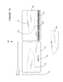
FIG. 1 illustrates an overall view of an embodiment of invention 100. As shown, embodiments of the invention include identification information 101 on an identification tag of a particular material, wherein a portion of the material 102 is configured to physically break the material into two or more portions, namely 103 and at least one tool 104. This enables tool 104 to remain safe while integrally coupled or a part of the apparatus, and until broken away from the second or remaining portion 103. The portion showing a knife along dotted lines 102 may be visible as shown, or may not be visible from the front of the apparatus if the portion of the material configured to enable the apparatus to break does not include holes that extend all the way through the apparatus.
FIG. 1A illustrates a detailed view of an embodiment of invention 100. The top view is shown in the upper left, the side view is shown on the far left, the front of the apparatus is shown as the left card format embodiment and the rear side of the apparatus is shown on the right of the figure. The tool is shown after breakaway in the bottom of the figure. Embodiments of the invention include a substantially flat material, shown in side view as flat material 110 to hold identification information 101. Although shown as raised letters in horizontal orientation, any orientation and type of lettering may be utilized if desired. For example, the lettering may be cut into or through the apparatus so that it cannot be erased. A portion of the material 102 is configured to physically break the material into two portions, including at least one tool 104 having a working edge 105 or point 106 or both. Embodiments of the invention may also include second working edge 107, for example serrations or another cutting edge or blade for example. The tool or tools may include but are not limited to one or more knives, saws, screwdrivers, pry bars, can openers, bottle openers, chisels, awls, wrenches and ice picks or any other relatively flat tool with a working edge or point or any combination thereof. See FIG. 5 for alternate embodiments of the tools.
One or more embodiments of the invention generally include a substantially flat material shown as side cross section 110 configured to hold identification information 101 wherein the substantially flat material has first side 111 and second side 112 that are on opposing sides of the substantially flat material and wherein the substantially flat material has a least a first thickness between the first side and the second side. The substantially flat material may be of uniform thickness, or have raised letters, that extend out of identification area 101 for example, such as is found on a credit card for example, while still maintaining a substantially flat form factor. The outer edges of the apparatus may also be utilized for handles as shown in FIGS. 6 and 7.
One or more embodiments may hold the identification information 101 in printed form, for example as shown, or as shown in the rear view on the right side as magnetic form 101 a or electronic form, for example a chip internal to the card as embodied with a smart card, which is not shown for brevity, or in any other form. The printed form information may be in the form of raised lettering or visible printing or both or as previously discussed, may be cut into or through the apparatus. Alternatively, or in combination, the magnetic form of information may be held for example on a magnetic strip that is configured to be read by a magnetic strip reader. Smart cards having electronic chips or other electronic media or memory may also be used alone or in combination to hold the identification information. The identification information may identify a bank account, a person, an address, or identify any other person, place, thing, service, task, or any other item.
The substantially flat material may be of any shape including rectangular as is shown in FIGS. 1 and 1A, with or without rounded corners for example, or square, trapezoidal, triangular, circular, elliptical, or any other shape (not shown for brevity) whether straight line segment or curved segment shape or any combination thereof as one skilled in the art will appreciate. The substantially flat material may constructed from or include any known material including metal, plastic, or any other material or combination thereof so long as the material is capable of holding identification information and may be configured to decouple into a portion that may be utilized as a tool for example.
FIG. 2 illustrates side cross sectional views of embodiments of the invention. In one or more embodiments of the invention, the substantially flat material may have one or more thicker portions or areas, as shown in the bottom two embodiments, between the two sides as long as that thickness is less than the height or width of the substantially flat material, whether angled or curved. In one or more embodiments, the thickness is much less than the width or height of the flat material, for example the thickness of a credit card. This is not required however and the substantially flat material may vary in thickness or be of a thickness for example greater than a millimeter if desired, or less depending on the material used in construction of the specific embodiment. The first thickness may for example represent the minimum distance between the two sides, not counting any indentations configured to tear or break. The material may have a linear or curvilinear cross section as well, as is shown in fourth embodiment down the page having top 111 a in which case the material includes at least a second thickness, or range of thickness up to the second thickness for example. This enables portions of the tool or identification card to have a stronger portion corresponding to the second thickness, or flat portions orthogonal to the two sides configured to enable manual manipulation for example. For example the bottommost embodiment is thicker on the right side and than on the left side.
Embodiments of the invention also generally include a portion 102 of the substantially flat material configured to physically break the substantially flat material into a first substantially flat portion and a second substantially flat portion. In one or more embodiments, the portion of the substantially flat material configured to physically break is configured with a thickness that is less than the first thickness as shown at 102 a, which may be indented on both sides as shown on the left or on one side as shown on the right with a deeper indentation for example. This may be in the form of dots or lines or any combination thereof that are indented into the material for example. Alternatively or in combination, the location to break may include holes 102 b, for example in a tear pathway or be of a hardness 102 c which differs from the rest of the material to enable tearing or other mechanisms of breakage to occur along a desired path so long as the substantially flat material is configured to physically break into at least two parts. The indentations or holes may be vertical, spherical or angled in any manner as shown with angled break areas 102 d and 102 e. Although break areas 102 d are shown having a finite width at the bottom, the break areas may angle or otherwise meet at a point at or near the bottom or rear of the apparatus to form extremely sharp edges when the two portions of the apparatus are separated. Angled portions may thus form cutting edges once the tool is decoupled with the other portion of the apparatus and the indentions or angled break areas may extend in any depth including to or nearly to the opposing side to make a sharp cutting edge for example. Any combination of any of the described break areas 102 a-e or any other mechanism may be utilized in any combination as is shown in the bottommost embodiment that includes indentations and hardness break areas for example.
FIG. 3 illustrates a rear view of an embodiment of the invention. Embodiments of the invention break into at least two parts wherein the first substantially flat portion includes a tool having a working edge or point or both the working edge and the point. Generally, the working edge is configured on an inner portion of the apparatus so that a sharp edge is not exposed and hence the identification tag is safe to carry for example. In one or more embodiments, the tool includes a knife having two substantially flat faces and wherein the working edge includes a blade. The right half of tool 104 is shown as two parallel lines that are not formed generally with slanted break areas such as may be utilized to form cutting edge 105. Thus, the right portion of the tool may be utilized as a handle for example. Alternatively or in combination the working edge or blade may include a serrated edge 107, or the serrated edge may be on an opposing side of the blade with respect to the working edge 105, e.g., sharp edge or cutting edge. The serrated edge is optional and may be in the form of flat edge or saw or any other shape for example. If serrated, angled break areas may be utilized to for the sharp portions. In addition, as shown, cylindrical cutouts may be formed to create serrations with extremely sharp edges with a shallow angle with respect to the flat portion of the surface of the apparatus. In addition, as shown cutting edge 105 may also employ linear angled break away portions that angle at a shallow angle to the break away or narrowest point of the apparatus to create an extremely sharp edge. One or more embodiments of the tool include a flat non-cutting edge opposite of the working edge, or for example next to the serrations at the top of the blade. The flat edge enables a finger to press on the flat portion to transfer force to the cutting edge of the blade for example.
FIG. 4 illustrates a rear view of a second embodiment of the invention. One or more embodiments of the knife include a first indentation 401 toward the blade that is configured to engage a bottle cap on a top side of the bottle cap with a first portion of the first indentation and configured to engage a bottom edge of the bottle cap with an opposing side of the first indentation to enable removal of the bottle cap. In one or more embodiments of the invention, indentation 401 includes a first and second wall that both slant down and back away from the distal end of the blade, however, the first and second wall may be any shape including linear or curved. The first and second walls meet at the innermost portion of indentation 401. The innermost portion of indentation 401 may also be linear or curved. Generally, the second wall provides a hook like area to pry a bottle cap as the first wall rests on top of the bottle cap. First indentation 401 is configured to engage a bottle cap on a top side of the bottle cap with a first portion of the first indentation, for example the left side of the indentation as shown, and also configured to engage a bottom edge of the bottle cap with an opposing side of the first indentation, for example the right side of the indentation as shown, to enable removal of the bottle cap. The depth of indentations 401 may be any depth deep enough and wide enough to remove a bottle cap. In addition, indentation 4901 may also be utilized as a pot lifter wherein opposing sides of the indentation may be utilized to lift a hot pot by the handle, or on the edge of a pan to lift the pan. In one or more embodiments, the flat top at the non-cutting area may be up to or greater than ⅛ of an inch, or at least 3/16 of an inch wide or any other dimension thicker than a standard knife. This enables the knife to be utilized as a wedge or splitter, to split wood for example. The wide flat top may be struck with a hammer or rock for example without breaking the blade.
Alternatively, the first or second portion, which are shown as the left and right sides of the indentation, may include a sharp portion enabling the portion to be utilized as a can opener. One or more embodiments of the blade may include a second indentation 402 configured to engage a wire to enable lateral angular movement of the blade to break the wire. The indentation enables a wire breaker and is also known as the wire break notch. The wire break notch is situated near the handle and also acts as a “choil” that allows sharpening for the entire blade length. The wire break notch may be aligned to indent towards the bottle cap opener indentation and visa versa so that the top and bottom indentations cooperate in the lashing configuration. This enables tool 104 to be utilized as a spear, axe or dead drop trap for example when lashing the blade to a pole for example.
One or more embodiments of the tool may further include jimping 403. Jimping slots on the top of the blade near the handle enable thumb contact with the blade that provides better control. The jimping in one or more embodiments is configured to provide a thumb grip on the non-cutting edge wherein the jimping is configured as two or more indentations of different size configured to grip wire insulation of different gauge to enable lateral translation movement of the blade to remove the wire insulation. One or more embodiments of the apparatus may include a lashing hole 410 or other method of coupling the apparatus to another object. In one or more embodiments, the lashing hole is formed in tool 104, in other embodiments the lashing hole may be in the other portion of the material that holds the identification information, which is not shown for brevity. Alternatively, the other portion and the tool portion may include holes or other coupling devices, as one skilled in the art will appreciate.
FIG. 5 illustrates a rear view of a third embodiment of the invention. One or more embodiments of the tool include a flat section configured as handle having a long axis and a short axis for example configured as the area of knife 104 a away from the tip. Other embodiments shown include handles on the right portions as shown respectively although there is no requirement for any tool to have any type of handle. Embodiments of the tool may also include any combination of at least one saw 104 b, screwdriver 104 c, pry bar 104 d, can opener 104 e, chisel 104 f, awl 104 g, ice pick 104 h, wrench 104 j, for example but not limited to a hex nut wrench, or can opener or bottle opener 104 k. The tools may be contiguous or separated from one another along non-common break areas as desired. Any portion of the apparatus, for example an exposed portion after break off, or an outer portion for example the left side, top or bottom as shown may be hardened, or combined with, or coupled with an object having carbide or plasma coated to enable use as a knife sharpener. In one or more embodiments a side edge of screwdriver 104 c or any other breakaway tool may also be hardened or contain a hardened object coupled therewith that defines a knife sharpener. In one or more embodiments a facing side or rear side of the substantially flat apparatus may be utilized as a sharpener if that embodiment is hardened for example. In other embodiments of the invention, a cutting edge or non-cutting edge of knife 104 a may be utilized as a knife or tool sharpener if hard enough for example. One or more embodiments of the invention may include a carbide or other hardened element that for example defines a sharp right angle edge with option concave face that may be utilized to sharpen a knife or other tool at a shallow angle and hone a knife or other tool when drawn over the edge to sharpen at a steeper angle.
FIG. 6 illustrates a rear view of a fourth embodiment of the invention. In one or more embodiments, the tool includes a knife having two substantially flat faces, for example the portions of the apparatus parallel to the plane of the written page, and wherein the working edge includes a blade. Serrated edges in this embodiment may be formed in a more economical manner by utilizing jagged edges cut into the apparatus at a linear slant for example as opposed to more curvilinear embodiments, e.g., as shown in FIG. 3. The right half of tool 104 is shown as two parallel lines that are part of the outer portion of the apparatus, i.e., on the edge of the apparatus. The portions of the apparatus that are configured to break are slanted break areas such as may be utilized to form cutting edge 105. Thus, the right portion of the tool may be utilized as a handle for example. Alternatively or in combination the working edge or blade may include a serrated edge 107, or the serrated edge may be on an opposing side of the blade with respect to the working edge 105, e.g., sharp edge or cutting edge. The serrated edge is optional and may be in the form of flat edge or saw or any other shape for example. If serrated, angled break areas may be utilized to for the sharp portions. One or more embodiments of the tool include a flat non-cutting edge opposite of the working edge, or for example next to the serrations at the top of the blade. The flat edge enables a finger to press on the flat portion to transfer force to the cutting edge of the blade for example. Embodiments of the invention may be less than, equal to or greater than 1 mm in depth, or for example less than, equal to or greater than 2 mm, or one quarter inch, ⅜ of an inch or any other thickness less than the width or height of the apparatus as previously described. Also shown is optional lashing hole, for example as use with an identification tag or luggage tag. Lashing hole 401 may be any shape including circular, oval, rectangular, or any other linear or curvilinear line containing shape. Identification information 101 is shown as cut entirely through the apparatus and in reverse orientation as seen from the rear portion of the apparatus. Alternatively or in combination, any printed identification information may be cut into or all the way through the apparatus or may be in any other form including that of a different material bonded or contained within the tool or other portion of the apparatus.
FIG. 7 illustrates a rear view of a fifth embodiment of the invention. In addition to the portion of the apparatus that remains after tool 104 is broken away, other portions may also be employed. For example, as shown, portions 103 a and 103 b may be removed individually to expose a sharp edge 105 a and 105 b respectively. If both portions 103 a and 103 b are removed, then point 106 a is exposed. This embodiment allows for one working edge, two working edges and a point, or if tool 104 is also broken away, then two points and up to four working edges, wherein any of the four working edges may be sharp or not. For example, in this embodiment another portion of the substantially flat material is configured to enable the substantially flat material to physically break into at least a third substantially flat portion after a corner of the substantially flat material is broken to expose a second working edge or second point, for example if both corners are broken away.
FIG. 8 illustrates a rear view of a sixth embodiment of the invention. In addition to the portion of the apparatus that remains after tool 104 is broken away, other portions may also be employed. For example, as shown, portion 103 a may be removed individually to expose a sharp edge 105 a and 105 b respectively, before or after tool 104 is broken away.
While the invention herein disclosed has been described by means of specific embodiments and applications thereof, numerous modifications and variations could be made thereto by those skilled in the art without departing from the scope of the invention set forth in the claims.

Claims (17)

What is claimed is:
1. An identification tag with breakaway tool comprising:
a substantially flat material configured to hold identification information wherein said substantially flat material comprises a first side and a second side that are on opposing sides of said substantially flat material and an outer edge that couples said first side with said second side and wherein said substantially flat material has a least a first thickness between said first side and said second side;
a portion of said substantially flat material configured to enable said substantially flat material to physically break into a first substantially flat portion and a second substantially flat portion;
wherein said first substantially flat portion comprises a tool having a working edge or a point or both said working edge and said point and wherein said working edge or point or both are not located on said outer edge of said substantially flat material and are exposed on an exposed edge of said first substantially flat portion after said substantially flat material is broken into said first and second substantially flat portions; and
wherein said tool comprises a knife having two substantially flat faces and wherein said working edge comprises a blade and having a flat non-cutting edge opposite of said working edge and wherein the non-cutting edge comprises jimping configured to provide a thumb grip on the non-cutting edge wherein the limping is configure as two or more indentations of different size configured to grip wire insulation of different gauge to enable lateral translation movement of the blade to remove the wire insulation.
2. The identification tag with breakaway tool of claim 1 wherein said substantially flat material comprises metal, or plastic or glass or composite material or any combination thereof.
3. The identification tag with breakaway tool of claim 1 wherein said substantially flat material is substantially rectangular.
4. The identification tag with breakaway tool of claim 1 wherein said identification information is in printed form or is in magnetic or is in electronic form or any combination thereof.
5. The identification tag with breakaway tool of claim 1 wherein said identification information is visible at least on said first side of said substantially flat material.
6. The identification tag with breakaway tool of claim 1 wherein said portion of said substantially flat material configured to physically break is configured with a thickness that is less than said first thickness.
7. The identification tag with breakaway tool of claim 1 wherein said portion of said substantially flat material configured to physically break is configured with a plurality of holes between said first side and said second side.
8. The identification tag with breakaway tool of claim 1 wherein said portion of said substantially flat material configured to physically break is configured with a hardness that differs from a hardness in another portion of said substantially flat material that is not configured to break.
9. The identification tag with breakaway tool of claim 1 wherein said working edge comprises a serrated edge.
10. The identification tag with breakaway tool of claim 1 wherein the non-cutting edge further comprises a first indentation toward the blade that is configured to engage a bottle cap on a top side of the bottle cap with a first portion of the first indentation and configured to engage a bottom edge of the bottle cap with an opposing side of the first indentation to enable removal of the bottle cap.
11. The identification tag with breakaway tool of claim 1 wherein the blade comprises a second indentation configured to engage said wire to enable lateral angular movement of the blade to break the wire.
12. The identification tag with breakaway tool of claim 1 wherein the non-cutting edge further comprises a first indentation toward the blade that is configured to engage a bottle cap on a top side of the bottle cap with a first portion of the first indentation and configured to engage a bottom edge of the bottle cap with an opposing side of the first indentation to enable removal of the bottle cap and wherein the blade comprises a second indentation configured to engage said wire to enable lateral angular movement of the blade to break the wire and wherein the first indentation and second indentation are indented toward one another to enable said blade to be lashed to another object with a line wrapped around said other object and said first indentation and said second indentation.
13. The identification tag with breakaway tool of claim 1 wherein said tool further comprises a flat section configured as a handle.
14. The identification tag with breakaway tool of claim 1 wherein said tool comprises any combination of one or more saws, screwdrivers, pry bars, can openers, chisels, awls, wrenches, ice picks or sharpeners.
15. The identification tag with breakaway tool of claim 1 wherein said portion of said substantially flat material is further configured to enable said substantially flat material to physically break into at least a third substantially flat portion another portion of said substantially flat material is broken to expose a second working edge or second point.
16. An identification tag with breakaway tool comprising:
a substantially flat material configured to hold identification information wherein said substantially flat material comprises a first side and a second side that are on opposing sides of said substantially flat material and an outer edge that couples said first side with said second side and wherein said substantially flat material has a least a first thickness between said first side and said second side;
a portion of said substantially flat material configured to enable said substantially flat material to physically break into a first substantially flat portion and a second substantially flat portion;
wherein said first substantially flat portion comprises a tool having a working edge or a point or both said working edge and said point and wherein said working edge or point or both are not located on said outer edge of said substantially flat material and are exposed on an exposed edge of said first substantially flat portion after said substantially flat material is broken into said first and second substantially flat portions; and,
wherein said tool comprises a knife having two substantially flat faces and wherein said working edge comprises a blade and having a flat non-cutting edge opposite of said working edge and wherein the non-cutting edge comprises a first indentation toward the blade that is configured to engage a bottle cap on a top side of the bottle cap with a first portion of the first indentation and configured to engage a bottom edge of the bottle cap with an opposing side of the first indentation to enable removal of the bottle cap.
17. An identification tag with breakaway tool comprising:
a substantially flat material configured to hold identification information wherein said substantially flat material comprises a first side and a second side that are on opposing sides of said substantially flat material and an outer edge that couples said first side with said second side and wherein said substantially flat material has a least a first thickness between said first side and said second side;
a portion of said substantially flat material configured to enable said substantially flat material to physically break into a first substantially flat portion and a second substantially flat portion;
wherein said first substantially flat portion comprises a tool having a working edge or a point or both said working edge and said point and wherein said working edge or point or both are not located on said outer edge of said substantially flat material and are exposed on an exposed edge of said first substantially flat portion after said substantially flat material is broken into said first and second substantially flat portions; and,
wherein said tool comprises a knife having two substantially flat faces and wherein said working edge comprises a blade and having a flat non-cutting edge opposite of said working edge and wherein the blade comprises a second indentation configured to engage a wire to enable lateral angular movement of the blade to break the wire.
US13/523,844 2011-06-14 2012-06-14 Identification tag with breakaway tool Active 2032-06-27 US9003665B2 (en)

Priority Applications (1)

Application Number Priority Date Filing Date Title
US13/523,844 US9003665B2 (en) 2011-06-14 2012-06-14 Identification tag with breakaway tool

Applications Claiming Priority (4)

Application Number Priority Date Filing Date Title
US201161496602P 2011-06-14 2011-06-14
US13/312,965 US8695138B2 (en) 2011-12-06 2011-12-06 Folding survival knife with integrated tools
US13/400,535 US8707490B1 (en) 2011-12-06 2012-02-20 Survival knife with integrated tools
US13/523,844 US9003665B2 (en) 2011-06-14 2012-06-14 Identification tag with breakaway tool

Related Parent Applications (1)

Application Number Title Priority Date Filing Date
US13/400,535 Continuation-In-Part US8707490B1 (en) 2011-06-14 2012-02-20 Survival knife with integrated tools

Publications (2)

Publication Number Publication Date
US20120317819A1 US20120317819A1 (en) 2012-12-20
US9003665B2 true US9003665B2 (en) 2015-04-14

Family

ID=47352536

Family Applications (1)

Application Number Title Priority Date Filing Date
US13/523,844 Active 2032-06-27 US9003665B2 (en) 2011-06-14 2012-06-14 Identification tag with breakaway tool

Country Status (1)

Country Link
US (1) US9003665B2 (en)

Cited By (5)

* Cited by examiner, † Cited by third party
Publication number Priority date Publication date Assignee Title
US20150308686A1 (en) * 2014-03-27 2015-10-29 Jashua Allen Hensley Bolt Cleaning and Fire Starting Survival Tool
US20160288972A1 (en) * 2015-04-01 2016-10-06 Readyman, Llc Tool kits
US9628891B2 (en) 2014-08-05 2017-04-18 John Fredrick Desautels Adhesivelessly customizable containment of a delicate electrical apparatus such as earbuds
USD853807S1 (en) * 2017-02-20 2019-07-16 Bold IP, PLLC Saw blade
USD957217S1 (en) * 2020-07-24 2022-07-12 Slice, Inc. Blade

Families Citing this family (3)

* Cited by examiner, † Cited by third party
Publication number Priority date Publication date Assignee Title
USD815935S1 (en) * 2014-10-29 2018-04-24 Alexander Baguma Barak Multi-tool
USD878891S1 (en) * 2018-10-11 2020-03-24 Ultimate Survival Tips Llc Tool card
IL265655A (en) * 2019-03-27 2020-09-30 Chen Altman Package and opening assembly therefore

Citations (102)

* Cited by examiner, † Cited by third party
Publication number Priority date Publication date Assignee Title
US1455621A (en) 1921-06-22 1923-05-15 William H Joyner Surgical saw
US2315898A (en) 1941-04-03 1943-04-06 James E Krilow Knife
US2440485A (en) 1944-03-11 1948-04-27 Mauritz C Ranseen Cap-lifting bottle opener
US2951482A (en) 1955-09-22 1960-09-06 Gregory B Sullivan Surgical saw
US3760438A (en) 1971-07-14 1973-09-25 J White Survival knife
USD245830S (en) 1975-07-21 1977-09-20 Francois de Gross & Cie. Bottle-opener
US4300610A (en) * 1980-01-31 1981-11-17 Bermas Plastics Company, Inc. Card-like holder
US4363147A (en) 1980-09-12 1982-12-14 Deweese Melvin T Survival tool
US4442559A (en) 1981-07-02 1984-04-17 Jenkins Metal Corporation Utility knife
US4553279A (en) 1983-10-17 1985-11-19 Gassew Garry L Multi-purpose paint stick
US4578864A (en) 1984-05-17 1986-04-01 Hoffman Phillip W Knife handle with thumb wing
US4622707A (en) 1985-04-17 1986-11-18 Finn, Camphuysen, Macdonald, Schumacher Survival knives with grapple capability
USD288895S (en) 1984-09-13 1987-03-24 Ensar Corporation Multi-purpose can opener
US4669140A (en) 1984-06-25 1987-06-02 Miceli Philip V Pocket folding tool and knife system
US4817221A (en) 1987-07-01 1989-04-04 Ryan William W Multipurpose survival tool
US4821356A (en) 1987-03-13 1989-04-18 Phrobis Iii, Ltd. Military bayonet and scabbard
USD308009S (en) 1987-11-23 1990-05-22 Eskilstuna Knivfabriks Ab Folding knife
US5259281A (en) 1991-09-27 1993-11-09 Burke Donald D Combination hand tool
US5328026A (en) * 1993-06-11 1994-07-12 Newman Chris M Flat multiple tool holder
USD360815S (en) * 1994-05-09 1995-08-01 Padden Stephen J Combined pocket implements and sheath
US5511310A (en) 1994-08-18 1996-04-30 Fiskars Inc. Folding knife
USD369287S (en) 1994-07-18 1996-04-30 Buck Knives, Inc. Folding knife
USD371289S (en) 1995-05-04 1996-07-02 Kuo-Tai Huang Knife-handle
USD371820S (en) 1995-02-07 1996-07-16 Thompson Lynn C Sport knife
USD374388S (en) * 1995-04-17 1996-10-08 Padden Stephen J Combined pocket implements and sheath
US5596808A (en) 1995-06-28 1997-01-28 Lake; Ronald W. Safety for knife-blade lock
US5620090A (en) * 1995-03-30 1997-04-15 Beeley; Robert A. Screwdriver kit
US5642567A (en) 1995-11-06 1997-07-01 Jia Shin Industrial Co., Ltd. Emergency escape apparatus for use in a car
US5657543A (en) 1995-10-10 1997-08-19 Collins; Walter W. Emergency tool
USD383370S (en) 1996-03-05 1997-09-09 Fiskars Inc. Knife handle with blade guard
USD385471S (en) 1994-09-16 1997-10-28 Buck Knives, Inc. Folding Knife
US5727319A (en) 1996-07-09 1998-03-17 Myerchin; John Knife with illuminated blade
US5727325A (en) 1996-05-07 1998-03-17 Mussell; Barry D. Multipurpose square
USD393405S (en) 1994-09-16 1998-04-14 Buck Knives, Inc. Folding knife for law enforcement
USD398211S (en) 1997-04-08 1998-09-15 Media Group Utility knife
US6009581A (en) 1998-05-21 2000-01-04 Davis; Dave D. Scraping tool having a tool socket and integral wrenches
US6009584A (en) 1997-11-26 2000-01-04 Padden; Stephen J. Multi-purpose tool with brush
US6009582A (en) 1996-10-29 2000-01-04 Swiss Army Brands, Inc. Multiple function tool
USD422669S (en) 1999-06-10 2000-04-11 Mentor Group, L.L.C. Fixed blade knife
USD425389S (en) 1999-06-10 2000-05-23 Mentor Group, L.L.C. Knife blade
US6085620A (en) 1995-05-26 2000-07-11 Anderson; Wayne Multiple driver cross-hole handtool
USD434624S (en) * 1999-06-21 2000-12-05 Padden Stephen J Multi-purpose entertainment tool
USD435409S (en) 2000-03-07 2000-12-26 Roberts Hess M Drum/barrel bung wrench
USD442461S1 (en) 2000-03-30 2001-05-22 Spyderco, Inc. Knife handle
USD446571S1 (en) 2000-11-21 2001-08-14 Sog Specialty Knives, Inc. Sporting knife
USD452123S1 (en) 2001-01-22 2001-12-18 Bison Designs, L.L.C. Gecko shaped bottle opener
US6347875B1 (en) 1997-08-08 2002-02-19 Victorinox Ag Functional part holder, especially a penknife
DE10130178A1 (en) 2001-06-22 2003-01-09 Reinhold Danny Multi-component multifunctional survival knife includes tip, smooth and corrugated-ground cutters, wire cutter, saw, nail-puller etc.
USD473917S1 (en) 2002-08-06 2003-04-29 United Cutlery, Inc. Knife
US6571940B2 (en) * 2001-06-01 2003-06-03 Chris M. Newman Flat article holder
US6574816B2 (en) 2001-09-28 2003-06-10 Hsiu-Man Yu Chen Emergency tool for automobiles
USD479970S1 (en) 2002-12-17 2003-09-30 Epm.Av Corporation Aircraft fuel cap opening tool
US6782576B1 (en) 2003-02-18 2004-08-31 Michael Valencic Survival tool
USD496425S1 (en) 2003-10-07 2004-09-21 United Cutlery Corporation Knife
USD497531S1 (en) 2003-07-24 2004-10-26 United Cutlery Corporation Knife
USD508194S1 (en) 2003-10-07 2005-08-09 United Cutlery Corporation Knife
US6957466B2 (en) 2000-10-31 2005-10-25 Leatherman Tool Group, Inc. Folding multipurpose pocket tool with floating springs
US20060027645A1 (en) 2004-02-12 2006-02-09 Granick Daniel H Identification tag with item holding feature
USD515654S1 (en) 2004-01-02 2006-02-21 Trbovich Jr Nicholas Knife
USD519185S1 (en) 2004-12-17 2006-04-18 United Cutlery Corporation Knife
US7036174B2 (en) * 1999-12-02 2006-05-02 Victorinox A.G Operational tools carrier
USD520825S1 (en) 2005-06-08 2006-05-16 Bison Designs, Llc Fish shaped bottle opener
USD523317S1 (en) 2005-04-11 2006-06-20 Surefire, Llc Folding knife
USD527788S1 (en) 2004-11-24 2006-09-05 Kel-Tec Cnc Industries, Inc. Foldable bayonet
US20070028452A1 (en) * 2005-08-05 2007-02-08 Lafauci Michael Device for opening packages
USD536593S1 (en) 2005-06-06 2007-02-13 Juan Carlos Fraga Utility knife with roller
USD553468S1 (en) 2006-03-15 2007-10-23 Fiskars Brands, Inc. Knife handle
USD553467S1 (en) 2006-02-22 2007-10-23 Surefire, Llc Knife
US20070245497A1 (en) 2006-04-25 2007-10-25 Leatherman Tool Group, Inc. Hand tool
US7302760B2 (en) 2004-01-05 2007-12-04 Fiskar Brands, Inc. Folding knife with dual-action piston
USD563755S1 (en) 2006-07-03 2008-03-11 Yuewei Wu Utility knife
USD566513S1 (en) * 2007-01-17 2008-04-15 Microtech Knives, Inc. Knife
US7360267B2 (en) 2004-03-18 2008-04-22 Philip J Quenzi Handheld multi-tool
US20080222895A1 (en) 2007-03-12 2008-09-18 Microtech Knives, Inc. Knife with window breaker
US20080271257A1 (en) 2007-05-01 2008-11-06 Spencer Frazer Wire stripping back bar knife
US20090000038A1 (en) 2007-05-31 2009-01-01 Padden Stephen J Plier tool combination
USD599641S1 (en) 2008-08-28 2009-09-08 Taylor Brands, Llc Folding knife
USD599640S1 (en) 2008-08-28 2009-09-08 Taylor Brands, Llc Folding knife
USD600090S1 (en) 2008-08-28 2009-09-15 Taylor Brands, Llc Folding knife
DE202009001850U1 (en) 2009-02-12 2009-12-24 Wiedewild, Andreas, Dipl.-Ing. (FH) Utility Knife Survival Knife for Camping, Hunting, Outdoor
USD609992S1 (en) 2007-10-10 2010-02-16 Delaney Robert N Multipurpose tool
US7676932B2 (en) 2003-12-29 2010-03-16 Tycelia Grice, legal representative Knife with spring-assisted blade articulation mechanism
USD614933S1 (en) 2009-10-02 2010-05-04 Fiskars Brands, Inc. Knife handle
USD624386S1 (en) 2009-02-12 2010-09-28 American Safety Razor Retractable blade knife
US7818843B2 (en) 2007-01-30 2010-10-26 Union Rich Usa Llc Multi-function tool apparatus and system
US20100299933A1 (en) 2009-05-27 2010-12-02 Blade-Tech Industries, Inc. Locking-folding utility knife
USD632154S1 (en) 2009-09-16 2011-02-08 Taylor Brands, Llc Folding knife
USD634174S1 (en) 2009-07-31 2011-03-15 Surefire, Llc Folding knife
US7913398B2 (en) 2008-04-29 2011-03-29 Li-Pen Chu Folding knife with an unlocking mechanism
USD639632S1 (en) 2009-10-02 2011-06-14 Fiskars Brands, Inc. Knife handle
USD642888S1 (en) 2009-07-31 2011-08-09 Surefire, Llc Folding knife
US20120017443A1 (en) 2010-07-22 2012-01-26 Wen Hao Side blade lock and release mechanism for use with a knife
USD653520S1 (en) 2010-12-14 2012-02-07 Wu-Chieh Chang Folding knife
USD654343S1 (en) 2009-07-27 2012-02-21 Yuewei Wu Utility knife
US20120110746A1 (en) * 2009-07-15 2012-05-10 Allard Serrano Jose Manuel Compact cutlery kit which manifests its previous use through release of its parts
USD672842S1 (en) 2012-06-01 2012-12-18 DPX Ventures Limited Knife
USD672841S1 (en) 2012-06-01 2012-12-18 DPX Ventures Limited Knife
USD675897S1 (en) 2010-05-21 2013-02-12 Yuewei Wu Dual head utility knife
USD677551S1 (en) 2011-12-06 2013-03-12 DPX Ventures Limited Folding knife
USD679975S1 (en) 2011-12-06 2013-04-16 DPX Ventures Limited Knife
US8464382B2 (en) 2011-02-16 2013-06-18 Jitung Chu Multi-functional folding knife
US20130232793A1 (en) * 2010-05-01 2013-09-12 Fatima Fazal Multiple purpose eating utensil assembly

Patent Citations (105)

* Cited by examiner, † Cited by third party
Publication number Priority date Publication date Assignee Title
US1455621A (en) 1921-06-22 1923-05-15 William H Joyner Surgical saw
US2315898A (en) 1941-04-03 1943-04-06 James E Krilow Knife
US2440485A (en) 1944-03-11 1948-04-27 Mauritz C Ranseen Cap-lifting bottle opener
US2951482A (en) 1955-09-22 1960-09-06 Gregory B Sullivan Surgical saw
US3760438A (en) 1971-07-14 1973-09-25 J White Survival knife
USD245830S (en) 1975-07-21 1977-09-20 Francois de Gross & Cie. Bottle-opener
US4300610A (en) * 1980-01-31 1981-11-17 Bermas Plastics Company, Inc. Card-like holder
US4363147A (en) 1980-09-12 1982-12-14 Deweese Melvin T Survival tool
US4442559A (en) 1981-07-02 1984-04-17 Jenkins Metal Corporation Utility knife
US4553279A (en) 1983-10-17 1985-11-19 Gassew Garry L Multi-purpose paint stick
US4578864A (en) 1984-05-17 1986-04-01 Hoffman Phillip W Knife handle with thumb wing
US4669140A (en) 1984-06-25 1987-06-02 Miceli Philip V Pocket folding tool and knife system
USD288895S (en) 1984-09-13 1987-03-24 Ensar Corporation Multi-purpose can opener
US4622707A (en) 1985-04-17 1986-11-18 Finn, Camphuysen, Macdonald, Schumacher Survival knives with grapple capability
US4821356A (en) 1987-03-13 1989-04-18 Phrobis Iii, Ltd. Military bayonet and scabbard
US4817221A (en) 1987-07-01 1989-04-04 Ryan William W Multipurpose survival tool
USD308009S (en) 1987-11-23 1990-05-22 Eskilstuna Knivfabriks Ab Folding knife
US5259281A (en) 1991-09-27 1993-11-09 Burke Donald D Combination hand tool
US5328026A (en) * 1993-06-11 1994-07-12 Newman Chris M Flat multiple tool holder
USD360815S (en) * 1994-05-09 1995-08-01 Padden Stephen J Combined pocket implements and sheath
USD369287S (en) 1994-07-18 1996-04-30 Buck Knives, Inc. Folding knife
US5511310A (en) 1994-08-18 1996-04-30 Fiskars Inc. Folding knife
USD385471S (en) 1994-09-16 1997-10-28 Buck Knives, Inc. Folding Knife
USD393405S (en) 1994-09-16 1998-04-14 Buck Knives, Inc. Folding knife for law enforcement
USD371820S (en) 1995-02-07 1996-07-16 Thompson Lynn C Sport knife
US5620090A (en) * 1995-03-30 1997-04-15 Beeley; Robert A. Screwdriver kit
USD374388S (en) * 1995-04-17 1996-10-08 Padden Stephen J Combined pocket implements and sheath
USD371289S (en) 1995-05-04 1996-07-02 Kuo-Tai Huang Knife-handle
US6318218B1 (en) 1995-05-26 2001-11-20 Wayne Anderson Hand/survival tool having multiple implements
US6085620A (en) 1995-05-26 2000-07-11 Anderson; Wayne Multiple driver cross-hole handtool
US5596808A (en) 1995-06-28 1997-01-28 Lake; Ronald W. Safety for knife-blade lock
US5657543A (en) 1995-10-10 1997-08-19 Collins; Walter W. Emergency tool
US5642567A (en) 1995-11-06 1997-07-01 Jia Shin Industrial Co., Ltd. Emergency escape apparatus for use in a car
USD383370S (en) 1996-03-05 1997-09-09 Fiskars Inc. Knife handle with blade guard
US5727325A (en) 1996-05-07 1998-03-17 Mussell; Barry D. Multipurpose square
US5727319A (en) 1996-07-09 1998-03-17 Myerchin; John Knife with illuminated blade
US6009582A (en) 1996-10-29 2000-01-04 Swiss Army Brands, Inc. Multiple function tool
USD398211S (en) 1997-04-08 1998-09-15 Media Group Utility knife
US6347875B1 (en) 1997-08-08 2002-02-19 Victorinox Ag Functional part holder, especially a penknife
US6009584A (en) 1997-11-26 2000-01-04 Padden; Stephen J. Multi-purpose tool with brush
US6009581A (en) 1998-05-21 2000-01-04 Davis; Dave D. Scraping tool having a tool socket and integral wrenches
USD422669S (en) 1999-06-10 2000-04-11 Mentor Group, L.L.C. Fixed blade knife
USD425389S (en) 1999-06-10 2000-05-23 Mentor Group, L.L.C. Knife blade
USD434624S (en) * 1999-06-21 2000-12-05 Padden Stephen J Multi-purpose entertainment tool
US7036174B2 (en) * 1999-12-02 2006-05-02 Victorinox A.G Operational tools carrier
USD435409S (en) 2000-03-07 2000-12-26 Roberts Hess M Drum/barrel bung wrench
USD442461S1 (en) 2000-03-30 2001-05-22 Spyderco, Inc. Knife handle
US6957466B2 (en) 2000-10-31 2005-10-25 Leatherman Tool Group, Inc. Folding multipurpose pocket tool with floating springs
US7415745B2 (en) 2000-10-31 2008-08-26 Leatherman Tool Group, Inc. Folding multipurpose pocket tool with floating springs
USD446571S1 (en) 2000-11-21 2001-08-14 Sog Specialty Knives, Inc. Sporting knife
USD452123S1 (en) 2001-01-22 2001-12-18 Bison Designs, L.L.C. Gecko shaped bottle opener
US6571940B2 (en) * 2001-06-01 2003-06-03 Chris M. Newman Flat article holder
DE10130178A1 (en) 2001-06-22 2003-01-09 Reinhold Danny Multi-component multifunctional survival knife includes tip, smooth and corrugated-ground cutters, wire cutter, saw, nail-puller etc.
US6574816B2 (en) 2001-09-28 2003-06-10 Hsiu-Man Yu Chen Emergency tool for automobiles
USD473917S1 (en) 2002-08-06 2003-04-29 United Cutlery, Inc. Knife
USD479970S1 (en) 2002-12-17 2003-09-30 Epm.Av Corporation Aircraft fuel cap opening tool
US6782576B1 (en) 2003-02-18 2004-08-31 Michael Valencic Survival tool
USD497531S1 (en) 2003-07-24 2004-10-26 United Cutlery Corporation Knife
USD496425S1 (en) 2003-10-07 2004-09-21 United Cutlery Corporation Knife
USD508194S1 (en) 2003-10-07 2005-08-09 United Cutlery Corporation Knife
US7676932B2 (en) 2003-12-29 2010-03-16 Tycelia Grice, legal representative Knife with spring-assisted blade articulation mechanism
USD515654S1 (en) 2004-01-02 2006-02-21 Trbovich Jr Nicholas Knife
US7302760B2 (en) 2004-01-05 2007-12-04 Fiskar Brands, Inc. Folding knife with dual-action piston
US20060027645A1 (en) 2004-02-12 2006-02-09 Granick Daniel H Identification tag with item holding feature
US7360267B2 (en) 2004-03-18 2008-04-22 Philip J Quenzi Handheld multi-tool
USD527788S1 (en) 2004-11-24 2006-09-05 Kel-Tec Cnc Industries, Inc. Foldable bayonet
USD519185S1 (en) 2004-12-17 2006-04-18 United Cutlery Corporation Knife
USD523317S1 (en) 2005-04-11 2006-06-20 Surefire, Llc Folding knife
USD536593S1 (en) 2005-06-06 2007-02-13 Juan Carlos Fraga Utility knife with roller
USD520825S1 (en) 2005-06-08 2006-05-16 Bison Designs, Llc Fish shaped bottle opener
US20070028452A1 (en) * 2005-08-05 2007-02-08 Lafauci Michael Device for opening packages
USD553467S1 (en) 2006-02-22 2007-10-23 Surefire, Llc Knife
USD553468S1 (en) 2006-03-15 2007-10-23 Fiskars Brands, Inc. Knife handle
US7337486B2 (en) 2006-04-25 2008-03-04 Leatherman Tool Group, Inc. Hand tool
US20070245497A1 (en) 2006-04-25 2007-10-25 Leatherman Tool Group, Inc. Hand tool
USD563755S1 (en) 2006-07-03 2008-03-11 Yuewei Wu Utility knife
USD566513S1 (en) * 2007-01-17 2008-04-15 Microtech Knives, Inc. Knife
US7818843B2 (en) 2007-01-30 2010-10-26 Union Rich Usa Llc Multi-function tool apparatus and system
US20080222895A1 (en) 2007-03-12 2008-09-18 Microtech Knives, Inc. Knife with window breaker
US20080271257A1 (en) 2007-05-01 2008-11-06 Spencer Frazer Wire stripping back bar knife
US20090000038A1 (en) 2007-05-31 2009-01-01 Padden Stephen J Plier tool combination
USD609992S1 (en) 2007-10-10 2010-02-16 Delaney Robert N Multipurpose tool
US7913398B2 (en) 2008-04-29 2011-03-29 Li-Pen Chu Folding knife with an unlocking mechanism
USD599640S1 (en) 2008-08-28 2009-09-08 Taylor Brands, Llc Folding knife
USD599641S1 (en) 2008-08-28 2009-09-08 Taylor Brands, Llc Folding knife
USD600090S1 (en) 2008-08-28 2009-09-15 Taylor Brands, Llc Folding knife
USD624386S1 (en) 2009-02-12 2010-09-28 American Safety Razor Retractable blade knife
DE202009001850U1 (en) 2009-02-12 2009-12-24 Wiedewild, Andreas, Dipl.-Ing. (FH) Utility Knife Survival Knife for Camping, Hunting, Outdoor
US20100299933A1 (en) 2009-05-27 2010-12-02 Blade-Tech Industries, Inc. Locking-folding utility knife
US20120110746A1 (en) * 2009-07-15 2012-05-10 Allard Serrano Jose Manuel Compact cutlery kit which manifests its previous use through release of its parts
USD654343S1 (en) 2009-07-27 2012-02-21 Yuewei Wu Utility knife
USD634174S1 (en) 2009-07-31 2011-03-15 Surefire, Llc Folding knife
USD642888S1 (en) 2009-07-31 2011-08-09 Surefire, Llc Folding knife
USD632154S1 (en) 2009-09-16 2011-02-08 Taylor Brands, Llc Folding knife
USD639632S1 (en) 2009-10-02 2011-06-14 Fiskars Brands, Inc. Knife handle
USD614933S1 (en) 2009-10-02 2010-05-04 Fiskars Brands, Inc. Knife handle
US20130232793A1 (en) * 2010-05-01 2013-09-12 Fatima Fazal Multiple purpose eating utensil assembly
USD675897S1 (en) 2010-05-21 2013-02-12 Yuewei Wu Dual head utility knife
US20120017443A1 (en) 2010-07-22 2012-01-26 Wen Hao Side blade lock and release mechanism for use with a knife
USD653520S1 (en) 2010-12-14 2012-02-07 Wu-Chieh Chang Folding knife
US8464382B2 (en) 2011-02-16 2013-06-18 Jitung Chu Multi-functional folding knife
USD677551S1 (en) 2011-12-06 2013-03-12 DPX Ventures Limited Folding knife
USD679975S1 (en) 2011-12-06 2013-04-16 DPX Ventures Limited Knife
USD672841S1 (en) 2012-06-01 2012-12-18 DPX Ventures Limited Knife
USD672842S1 (en) 2012-06-01 2012-12-18 DPX Ventures Limited Knife

Non-Patent Citations (20)

* Cited by examiner, † Cited by third party
Title
"Microtech Troodon Double Edge OTF Knife, Beadblast Plain Edge, 138-7" BladeOps, LLC, 2 pages.
Blackwater Aculus Limited Edition Knife. Http://www.dpxgear.com/shop/aculus-coming-soon.html, Jun. 2, 2013.
Boker Plus Credit Card Knife 2-1/4'' Blade, retrieved from http://www.Knifecenter.com on Jul. 24, 2012, 2 pages.
Boker Plus Credit Card Knife 2-1/4″ Blade, retrieved from http://www.Knifecenter.com on Jul. 24, 2012, 2 pages.
CRKT "ExiTool-Designed by Russ Kommer", Columbia River Knife & Tool Inc., 3 pages.
CRKT "ExiTool—Designed by Russ Kommer", Columbia River Knife & Tool Inc., 3 pages.
CRKT Columbia River Knife and Tool's Exitool 9030 Multi Tool, retrieved from http://www.amazon.com/Columbia-River-Knife-Exitool-9030/dp/B0030IV8TG on Jul, 24, 2012, 6 pages.
DPx Hest 2.0 Knife Survival Blade, http://www.bladehq.com/item--ESEE-DPx-HEST-Folder--6996, downloaded Sep. 26, 2012.
DPx Hest 2.0 Knife Survival Blade, http://www.bladehq.com/item--ESEE-DPx—HEST-Folder--6996, downloaded Sep. 26, 2012.
Extended European Patent Search, dated Mar. 15, 2013, 5 pages.
Iain Sinclair, CardSharp 2, retrieved from http://iainsinclair.com/products.php on Jul. 24, 2012, 1 page.
ICE Companion with Lens/Compass-Translucent, retrieved from http://www.sogshopping.com/tools/icc1-12.html!SID=pp1bedicbg7gm82okgt77lacd6 on Jul. 24, 2012, 1 page.
ICE Companion with Lens/Compass—Translucent, retrieved from http://www.sogshopping.com/tools/icc1-12.html!SID=pp1bedicbg7gm82okgt77lacd6 on Jul. 24, 2012, 1 page.
Microtech Troodon Double Edge OTF Knife, Beadblast Plain Edge, 138-7, BladeOps, LLC, retrieved from http://www.bladeops.com/Microtech-Troodon-Double-Edge-OTF-Knife-BeadBlas-p on Jul. 24, 2012, 2 pages.
Ontario Hest Original Fixed Blade. Downloaded from http://www.sears.com/ontario-hest-origina-fixed-blade/p-SPM6596962201?prdNo=2&bl . . . on Nov. 16, 2012.
SE MT908 11 Function Credit Card Size Survival Pocket Tool, retrieved from http://www.amazon.com/SE-MT908-Function-Credit-Survival/dp/B000Q06LI4 on Jul. 24, 2012, 6 pages.
Sheffield Moab Folding Rescue Knife, http://www.autogeek,net/sheffield-rescue-knife.html, downloaded Sep. 27, 2012.
Survival Card w/ Fire Starter/Compass-Charcoal, retrieved from http://www.toollogic.com/tools/svc1-38.html on Jul. 24, 2012, 1 page.
Survival Card w/ Fire Starter/Compass—Charcoal, retrieved from http://www.toollogic.com/tools/svc1-38.html on Jul. 24, 2012, 1 page.
The Original Dog Tag Knife, Titanium Blade, Black Rubber Frame, retrieved from http://www.knifeworks.com/theoriginaldogtagknifetitaniumblade.aspx on Jul. 24, 2012, 4 pages.

Cited By (7)

* Cited by examiner, † Cited by third party
Publication number Priority date Publication date Assignee Title
US20150308686A1 (en) * 2014-03-27 2015-10-29 Jashua Allen Hensley Bolt Cleaning and Fire Starting Survival Tool
US9464806B2 (en) * 2014-03-27 2016-10-11 Jashua Allen Hensley Bolt cleaning and fire starting survival tool
US9628891B2 (en) 2014-08-05 2017-04-18 John Fredrick Desautels Adhesivelessly customizable containment of a delicate electrical apparatus such as earbuds
US20160288972A1 (en) * 2015-04-01 2016-10-06 Readyman, Llc Tool kits
US10661957B2 (en) * 2015-04-01 2020-05-26 Readyman, Llc Tool kits
USD853807S1 (en) * 2017-02-20 2019-07-16 Bold IP, PLLC Saw blade
USD957217S1 (en) * 2020-07-24 2022-07-12 Slice, Inc. Blade

Also Published As

Publication number Publication date
US20120317819A1 (en) 2012-12-20

Similar Documents

Publication Publication Date Title
US9003665B2 (en) Identification tag with breakaway tool
US8695138B2 (en) Folding survival knife with integrated tools
US20190359465A1 (en) Bag Cutter and Piercer
US6142769A (en) Multi-purpose tool
US8713735B1 (en) Compact survival tool
US8015642B1 (en) Multipurpose handheld tool and associated method
US8161654B2 (en) Four point utility blade and method
US3461469A (en) Multipurpose tools and wallet holders therefor
EP1889691A3 (en) A Multi-Use Demolition Tool
WO2010078007A3 (en) Tool with ergonomic handle and replaceable cutter head
US20100101028A1 (en) Multi-function tool including a letter opener and staple remover
US20070028452A1 (en) Device for opening packages
US7003884B2 (en) Cutting tool
US20050205506A1 (en) Tool holder with markings
CN202507297U (en) Multipurpose folding knife
US4805250A (en) Blade pick and well cleaner
US10828764B2 (en) Key shaped multitool
US20200030998A1 (en) Fine task friction grip on a multi-purpose knife
US11084938B2 (en) Composite coating on a contact face of a tool
US1287413A (en) Combination-tool.
US20070214651A1 (en) Cutting tool
RO132085A0 (en) Multifunctional device
US20050132577A1 (en) Sheet metal penetrating tool
EP2025257A2 (en) Pocket tool and combination thereof with key
US2043907A (en) Hatchet

Legal Events

Date Code Title Description
AS Assignment

Owner name: DPX VENTURES LIMITED, UNITED ARAB EMIRATES

Free format text: ASSIGNMENT OF ASSIGNORS INTEREST;ASSIGNOR:PELTON, ROBERT YOUNG;REEL/FRAME:028432/0360

Effective date: 20120609

STCF Information on status: patent grant

Free format text: PATENTED CASE

FEPP Fee payment procedure

Free format text: SURCHARGE FOR LATE PAYMENT, SMALL ENTITY (ORIGINAL EVENT CODE: M2554); ENTITY STATUS OF PATENT OWNER: SMALL ENTITY

MAFP Maintenance fee payment

Free format text: PAYMENT OF MAINTENANCE FEE, 4TH YR, SMALL ENTITY (ORIGINAL EVENT CODE: M2551); ENTITY STATUS OF PATENT OWNER: SMALL ENTITY

Year of fee payment: 4

AS Assignment

Owner name: ADVENTURIST CORP, CALIFORNIA

Free format text: ASSIGNMENT OF ASSIGNORS INTEREST;ASSIGNOR:DPX VENTURES LIMITED;REEL/FRAME:048460/0772

Effective date: 20190201

MAFP Maintenance fee payment

Free format text: PAYMENT OF MAINTENANCE FEE, 8TH YR, SMALL ENTITY (ORIGINAL EVENT CODE: M2552); ENTITY STATUS OF PATENT OWNER: SMALL ENTITY

Year of fee payment: 8