US8998026B2 - Bottle formed of synthetic resin material into cylindrical shape with bottom - Google Patents
Bottle formed of synthetic resin material into cylindrical shape with bottom Download PDFInfo
- Publication number
- US8998026B2 US8998026B2 US14/131,595 US201214131595A US8998026B2 US 8998026 B2 US8998026 B2 US 8998026B2 US 201214131595 A US201214131595 A US 201214131595A US 8998026 B2 US8998026 B2 US 8998026B2
- Authority
- US
- United States
- Prior art keywords
- wall portion
- bottle
- circumferential wall
- grounding
- movable wall
- Prior art date
- Legal status (The legal status is an assumption and is not a legal conclusion. Google has not performed a legal analysis and makes no representation as to the accuracy of the status listed.)
- Active
Links
Images


Classifications
-
- B—PERFORMING OPERATIONS; TRANSPORTING
- B65—CONVEYING; PACKING; STORING; HANDLING THIN OR FILAMENTARY MATERIAL
- B65D—CONTAINERS FOR STORAGE OR TRANSPORT OF ARTICLES OR MATERIALS, e.g. BAGS, BARRELS, BOTTLES, BOXES, CANS, CARTONS, CRATES, DRUMS, JARS, TANKS, HOPPERS, FORWARDING CONTAINERS; ACCESSORIES, CLOSURES, OR FITTINGS THEREFOR; PACKAGING ELEMENTS; PACKAGES
- B65D1/00—Containers having bodies formed in one piece, e.g. by casting metallic material, by moulding plastics, by blowing vitreous material, by throwing ceramic material, by moulding pulped fibrous material, by deep-drawing operations performed on sheet material
- B65D1/02—Bottles or similar containers with necks or like restricted apertures, designed for pouring contents
-
- B—PERFORMING OPERATIONS; TRANSPORTING
- B65—CONVEYING; PACKING; STORING; HANDLING THIN OR FILAMENTARY MATERIAL
- B65D—CONTAINERS FOR STORAGE OR TRANSPORT OF ARTICLES OR MATERIALS, e.g. BAGS, BARRELS, BOTTLES, BOXES, CANS, CARTONS, CRATES, DRUMS, JARS, TANKS, HOPPERS, FORWARDING CONTAINERS; ACCESSORIES, CLOSURES, OR FITTINGS THEREFOR; PACKAGING ELEMENTS; PACKAGES
- B65D1/00—Containers having bodies formed in one piece, e.g. by casting metallic material, by moulding plastics, by blowing vitreous material, by throwing ceramic material, by moulding pulped fibrous material, by deep-drawing operations performed on sheet material
- B65D1/40—Details of walls
-
- B—PERFORMING OPERATIONS; TRANSPORTING
- B65—CONVEYING; PACKING; STORING; HANDLING THIN OR FILAMENTARY MATERIAL
- B65D—CONTAINERS FOR STORAGE OR TRANSPORT OF ARTICLES OR MATERIALS, e.g. BAGS, BARRELS, BOTTLES, BOXES, CANS, CARTONS, CRATES, DRUMS, JARS, TANKS, HOPPERS, FORWARDING CONTAINERS; ACCESSORIES, CLOSURES, OR FITTINGS THEREFOR; PACKAGING ELEMENTS; PACKAGES
- B65D1/00—Containers having bodies formed in one piece, e.g. by casting metallic material, by moulding plastics, by blowing vitreous material, by throwing ceramic material, by moulding pulped fibrous material, by deep-drawing operations performed on sheet material
- B65D1/02—Bottles or similar containers with necks or like restricted apertures, designed for pouring contents
- B65D1/0223—Bottles or similar containers with necks or like restricted apertures, designed for pouring contents characterised by shape
- B65D1/0261—Bottom construction
- B65D1/0276—Bottom construction having a continuous contact surface, e.g. Champagne-type bottom
Definitions
- the present invention relates to a bottle.
- Patent Document 1 As a bottle that is formed of a synthetic resin material in a cylindrical shape with a bottom, the constitution of a bottle described in, for instance, Patent Document 1 below has been known from the past.
- a constitution is disclosed in which a bottom wall portion of a bottom portion includes a grounding portion that is located at an outer circumferential edge, a rising circumferential wall portion that is connected from a bottle radial inner side to the grounding portion and extends upward, a movable wall portion that protrudes from an upper end of the rising circumferential wall portion toward the bottle radial inner side, and a recessed circumferential wall portion that extends upward from a bottle radial inner end of the movable wall portion, and a pressure reduced in the bottle is absorbed by rotating the bottom wall portion around a portion connected to the rising circumferential wall portion such that the movable wall portion moves the recessed circumferential wall portion in an upward direction.
- bottom collapse refers to, as described above, a phenomenon that causes failure in grounding stability.
- a first object of the present invention is to provide a bottle capable of securing pressure reduction-absorbing performance while suppressing occurrence of bottom collapse.
- a second object of the present invention is to provide a bottle capable of improving performance of absorbing a pressure reduced in the bottle.
- a bottle that is formed of a synthetic resin material in a cylindrical shape with a bottom, and a bottom wall portion of a bottom portion thereof includes a grounding portion, a rising circumferential wall portion, an annular movable wall portion, and a recessed circumferential wall portion.
- the grounding portion is located at an outer circumferential edge.
- the rising circumferential wall portion is connected from a bottle radial inner side to the grounding portion, and extends upward.
- the annular movable wall portion protrudes from an upper end of the rising circumferential wall portion toward the bottle radial inner side.
- the recessed circumferential wall portion is connected from the bottle radial inner side to the movable wall portion, and extends upward.
- the movable wall portion is disposed to be free to rotate around a portion connected to the rising circumferential wall portion so as to move the recessed circumferential wall portion in an upward direction.
- the rising circumferential wall portion extends so as to be gradually inclined toward the bottle radial inner side with the approach from the grounding portion to the portion connected to the movable wall portion, and an inclined angle thereof is equal to or less than 10° with respect to a bottle axis.
- the movable wall portion when a pressure is reduced in the bottle, the movable wall portion can rotate around the portion connected to the rising circumferential wall portion in an upward direction, and the recessed circumferential wall portion can be moved upward. For this reason, a volume of reduced-pressure absorption of the bottle can be increased to secure predetermined pressure reduction-absorbing performance.
- the rising circumferential wall portion is inclined toward the bottle radial inner side with respect to the bottle axis with the approach to the portion connected to the movable wall portion.
- an inclined angle of the rising circumferential wall portion is equal to or less than 10°, and is formed in a state adjacent to an upright form.
- the upper end side (the connecting portion side) of the rising circumferential wall portion can be inhibited from easily moving in a bottle radial direction.
- the movable wall portion is easily inhibited from rotating around the connecting portion in a downward direction during filling of contents. Thereby, it can be difficult to cause so-called bottom collapse.
- a height from the grounding portion to the connecting portion between the rising circumferential wall portion and the movable wall portion exceeds 7.5 mm.
- the connecting portion of the movable wall portion which serves as the rotational center is located at the height exceeding 7.5 mm from the grounding portion, it can be more difficult to cause the so-called bottom collapse during filling of contents. For this reason, it is possible to secure stable grounding performance, and to cope with, for example, high-temperature filling of the contents.
- the movable wall portion gradually extends downward with the approach from an outer end thereof, which is connected to the rising circumferential wall portion, to an inner end thereof, which is connected to the recessed circumferential wall portion.
- a height from the grounding portion to a lowermost end of the movable wall portion has a range between 35% and 65% of a height from the grounding portion to the outer end of the movable wall portion.
- the recessed circumferential wall portion moves upward by means of the rotation of the movable wall portion.
- the reduced pressure can be absorbed.
- the height from the grounding portion to the lowermost end of the movable wall portion is equal to or less than 65% of the height from the grounding portion to the outer end of the movable wall portion, and a great height difference between the outer end and the lowermost end of the movable wall portion is secured.
- the movable wall portion is easily rotated downward. For this reason, it is possible to increase an internal volume of the bottle and to raise a volume of reduced-pressure absorption just after the filling. Thereby, the pressure reduction-absorbing performance can be improved.
- the height from the grounding portion to the lowermost end is equal to or more than 35% of the height from the grounding portion to the outer end of the movable wall portion, and a distance between the lowermost lower end and the grounding portion is sufficiently secured.
- the height of the lowermost end of the movable wall portion from the grounding portion is equal to or more than 3 mm.
- the lowermost end of the movable wall portion can be sufficiently separated from the grounding plane in an upward direction, or the swelling can be more reliably suppressed.
- the bottle it is possible to secure the pressure reduction-absorbing performance while the occurrence of the bottom collapse is suppressed during filling of contents or raising of internal pressure.
- the bottle it is possible to improve the performance of absorbing the pressure reduced in the bottle.
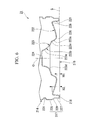
- FIG. 1 is a front view of a bottle in a first embodiment of the present invention.
- FIG. 2 is a bottom view of the bottle shown in FIG. 1 .
- FIG. 3 is a cross-sectional view of the bottle taken along line A-A shown in FIG. 2 .
- FIG. 4 is a front view of a bottle in a second embodiment of the present invention.
- FIG. 5 is a bottom view of the bottle shown in FIG. 4 .
- FIG. 6 is a cross-sectional view of the bottle taken along line B-B shown in FIG. 5 .
- FIG. 7 is a bottom view of a bottle showing a modification according to the embodiment of the present invention.
- FIG. 8 is a cross-sectional view of the bottle taken along line C-C shown in FIG. 7 .
- FIGS. 1 to 3 a bottle according to a first embodiment of the present invention will be described with reference to FIGS. 1 to 3 .
- the bottle 11 includes a mouth portion 111 , a shoulder portion 112 , a body portion 113 , and a bottom portion 114 .
- the mouth portion 111 , the shoulder portion 112 , the body portion 113 , and the bottom portion 114 are continuously connected in this order with respective central axes thereof disposed on a common axis.
- a bottle axis O a side of the mouth portion 111 is referred to as an upper side, and a side of the bottom portion 114 is referred to as a lower side.
- a direction perpendicular to the bottle axis O is referred to as a bottle radial direction, and a direction going around the bottle axis O is referred to as a bottle circumferential direction.
- a preform formed in a cylindrical shape with a bottom by injection molding is formed by blow molding, and is integrally formed of a synthetic resin material. Further, a cap (not shown) is screwed onto the mouth portion 111 . Further, each of the mouth portion 111 , the shoulder portion 112 , the body portion 113 , and the bottom portion 114 is formed in a circular shape when viewed from a cross portion perpendicular to the bottle axis O.
- a first annular groove 115 is continuously formed between the shoulder portion 112 and the body portion 113 throughout the circumference of the body portion 113 .
- the body portion 113 is formed in a tubular shape, and has a smaller diameter than a lower end of the shoulder portion 112 and a heel portion 117 of the bottom portion 114 which will be described below.
- the body portion 113 is formed with a plurality of second annular grooves 116 that are spaced apart from one another in the direction of the bottle axis O. In the example of FIG. 1 , five second annular grooves 116 are formed at regular intervals in the direction of the bottle axis O.
- Each of the second annular grooves 116 is a groove that is continuously formed throughout the circumference of the body portion 113 .
- the bottom portion 114 is formed in the shape of a cup having a heel portion 117 and a bottom wall portion 119 .
- An upper opening section of the heel portion 117 is connected to a lower opening section of the body portion 113 .
- the bottom wall portion 119 blocks a lower opening section of the heel portion 117 , and an outer circumferential edge thereof serves as a grounding portion 118 .
- a lower heel edge portion 127 of the heel portion 117 which is connected from a bottle radial outer side to the grounding portion 118 is formed with a smaller diameter than an upper heel portion 128 that is connected from above to the lower heel edge portion 127 .
- the upper heel portion 128 is a maximum outer diameter portion of the bottle 11 along with the lower end of the shoulder portion 112 .
- connection part 129 between the lower heel edge portion 127 and the upper heel portion 128 is gradually reduced in diameter with the approach from top to bottom. Thereby, the lower heel edge portion 127 is formed with the smaller diameter than the upper heel portion 128 .
- a plurality of third annular grooves 120 are continuously formed in the upper heel portion 128 throughout the circumference of the upper heel portion 128 .
- two third annular grooves 120 are formed at intervals in the direction of the bottle axis O.
- the bottom wall portion 119 includes a rising circumferential wall portion 121 , an annular movable wall portion 122 , and a recessed circumferential wall portion 123 .
- the rising circumferential wall portion 121 is connected from the bottle radial inner side to the grounding portion 118 and extends upward.
- the annular movable wall portion 122 protrudes from an upper end of the rising circumferential wall portion 121 toward the bottle radial inner side.
- the recessed circumferential wall portion 123 extends upward from a bottle radial inner end of the movable wall portion 122 .
- the movable wall portion 122 is formed in the shape of a curved surface that protrudes downward, and gradually extends downward with the approach from the bottle radial outer side to the bottle radial inner side.
- This movable wall portion 122 and the rising circumferential wall portion 121 are connected via a curved surface part 125 that protrudes upward. Then, to cause the recessed circumferential wall portion 123 to move upward, the movable wall portion 122 is formed to be free to rotate around the curved surface part (part connected to the rising circumferential wall portion 121 ) 125 .
- the rising circumferential wall portion 121 is gradually reduced in diameter with the approach from bottom to top.
- the rising circumferential wall portion 121 extends so as to be gradually inclined toward the bottle radial inner side with the approach from the grounding portion 118 to the curved surface part 125 that is a part connected to the movable wall portion 122 .
- an inclined angle ⁇ is equal to or less than 10° with respect to the bottle axis O.
- a height T from the grounding portion 118 to the curved surface part 125 is a height exceeding 7.5 mm.
- the height T is 7.7 mm.
- the recessed circumferential wall portion 123 is disposed on the same axis as the bottle axis O, and is formed in a circular shape that gradually increases in diameter with the approach from top to bottom when viewed from a cross section.
- a disc-shaped top wall 124 disposed on the same axis as the bottle axis O is connected to an upper end of the recessed circumferential wall portion 123 .
- a cylindrical shape with a top is formed by both of the recessed circumferential wall portion 123 and the top wall 124 .
- the recessed circumferential wall portion 123 is formed in the shape of a curved surface that protrudes toward the bottle radial inner side, and the upper end thereof has a curved wall 123 a connected to an outer circumferential edge of the top wall 124 .
- a lower end of the curved wall 123 a is connected to the bottle radial inner end of the movable wall portion 122 via the curved surface part 126 that protrudes downward.
- the movable wall portion 122 When a pressure inside of the bottle 11 constituted in this way is reduced, the movable wall portion 122 is rotated around the curved surface part 125 of the bottom wall portion 119 in an upward direction. Thereby, the movable wall portion 122 moves so as to raise the recessed circumferential wall portion 123 in an upward direction. In other words, when the pressure is reduced, the bottom wall portion 119 of the bottle 11 is actively deformed, and thereby a change in internal pressure (reduced pressure) of the bottle 11 can be absorbed. Thereby, predetermined pressure reduction-absorbing performance can be secured.
- the rising circumferential wall portion 121 is inclined to the bottle radial inner side with the approach to the curved surface part 125 .
- the inclined angle ⁇ of the rising circumferential wall portion 121 is equal to or less than 10 degrees with respect to the bottle axis O, and is formed in a state adjacent to an upright form.
- the upper end side (side of the curved surface part 125 ) of the rising circumferential wall portion 121 can be inhibited from easily moving in a bottle radial direction.
- the movable wall portion 122 is easily inhibited from rotating around the curved surface part 125 in a downward direction.
- the rising circumferential wall portion 121 is inhibited from being deformed and collapsing onto the bottle radial inner side. Thereby, it is possible to prevent so-called bottom collapse from easily occurring.
- the curved surface part 125 serving as the rotational center of the movable wall portion 122 is disposed at a height that is located 7.7 mm above the grounding portion 118 . For this reason, even when the movable wall portion 122 is somewhat rotated in a downward direction, it is easy to prevent occurrence of the bottom collapse. For this reason, it is possible to secure stable grounding performance, and to cope with, for example, high-temperature filling of the contents (e.g. from 80 to 100° C., and preferably from 85 to 93° C.).
- high-temperature filling of the contents e.g. from 80 to 100° C., and preferably from 85 to 93° C.
- the bottle 11 of the first embodiment is suitable for a bottle in which contents are equal to or less than 1 liter and a grounding diameter is equal to or less than 85 mm.
- the example of FIG. 3 is a bottle in which the grounding diameter is 70 mm and the height T of the curved surface part 125 from the grounding portion 118 is 7.7 mm.
- the inclined angle ⁇ of the rising circumferential wall portion 121 is preferably equal to or less than 10 degrees. More preferably, the inclined angle ⁇ of the rising circumferential wall portion 121 is equal to or less than 3 degrees.
- the movable wall portion 122 may be appropriately modified, for example, may protrude in parallel in the bottle radial direction or be inclined upward.
- the movable wall portion 122 may be appropriately modified, for example, may be formed in a planar shape or in a concave surface recessed upward.
- the movable wall portion 122 may also be made up of an outer wall portion that gradually extends downward with the approach from the curved surface part 125 to the bottle radial inner side and an inner wall portion that connects the outer wall portion and the recessed circumferential wall portion and is formed in a concave surface recessed upward.
- each of the shoulder portion 112 , the body portion 113 , and the bottom portion 114 has the circular shape when viewed from the cross section perpendicular to the bottle axis O.
- the shape may be appropriately modified, for example, to a polygonal shape when viewed from the cross section.
- the synthetic resin material forming the bottle 11 may be appropriately modified into, for instance, polyethylene terephthalate, polyethylene naphthalate, amorphous polyester, or a blend material thereof.
- the bottle 11 is not limited to a single-layer structure, and may be a laminated structured having an intermediate layer.
- the intermediate layer includes, for instance, a layer formed of a resin material having a gas barrier characteristic, a layer formed of a recycled material, or a layer formed of a resin material having oxygen absorbability.
- a predetermined internal pressure (0.5 kg/cm 2 (49 KPa)) was applied into the bottles 11 having the rising circumferential wall portions 121 of the total of eight patterns on the assumption that contents were filled in the bottle.
- a bottle 21 includes a mouth portion 211 , a shoulder portion 212 , a body portion 213 , and a bottom portion 214 .
- the mouth portion 211 , the shoulder portion 212 , the body portion 213 , and the bottom portion 214 are continuously connected in this order with respective central axes thereof disposed on a common axis.
- a bottle axis O a side of the mouth portion 211 is referred to as an upper side, and a side of the bottom portion 214 is referred to as a lower side.
- a direction perpendicular to the bottle axis O is referred to as a bottle radial direction, and a direction going around the bottle axis O is referred to as a bottle circumferential direction.
- a preform formed in a cylindrical shape with a bottom by injection molding is formed by blow molding, and is integrally formed of a synthetic resin material. Further, a cap (not shown) is screwed onto the mouth portion 211 . Further, each of the mouth portion 211 , the shoulder portion 212 , the body portion 213 , and the bottom portion 214 is formed in a circular shape when viewed from a cross section perpendicular to the bottle axis O.
- a first annular groove 216 is continuously formed in a connection part between the shoulder portion 212 and the body portion 213 throughout the circumference of the connection part.
- the body portion 213 is formed in a tubular shape, and is formed between opposite ends thereof in the direction of the bottle axis O with a smaller diameter than the opposite ends.
- the body portion 213 is formed with a plurality of second annular grooves 215 that are spaced apart from one another in the direction of the bottle axis O.
- four second annular grooves 215 are formed at regular intervals in the direction of the bottle axis O.
- Each of the second annular grooves 215 is a groove that is continuously formed throughout the circumference of the body portion 213 .
- a third annular groove 220 is continuously formed in a connection part between the body portion 213 and the bottom portion 214 throughout the circumference of the connection part.
- the bottom portion 214 is formed in the shape of a cup that has a heel portion 217 whose upper opening section thereof is connected to a lower opening section of the body portion 213 and a bottom wall portion 219 which blocks a lower opening section of the heel portion 217 and whose outer circumferential edge serves as a grounding portion 218 .
- a lower heel edge portion 227 of the heel portion 217 which is connected from a bottle radial outer side to the grounding portion 218 is formed with a smaller diameter than an upper heel portion 228 that is connected from above to the lower heel edge portion 227 .
- the upper heel portion 228 is a maximum outer diameter portion of the bottle 21 along with the opposite ends of the body portion 213 in the direction of the bottle axis O.
- connection part 229 between the lower heel edge portion 227 and the upper heel portion 228 is gradually reduced in diameter with the approach from top to bottom. Thereby, the lower heel edge portion 227 is formed with the smaller diameter than the upper heel portion 228 .
- a fourth annular groove 231 which has approximately the same depth as the third annular groove 220 , is continuously formed in the upper heel portion 228 throughout the circumference of the upper heel portion 228 .
- the bottom wall portion 219 includes a rising circumferential wall portion 221 , an annular movable wall portion 222 , and a recessed circumferential wall portion 223 .
- the rising circumferential wall portion 221 is connected from the bottle radial inner side to the grounding portion 218 and extends upward.
- the annular movable wall portion 222 protrudes from an upper end of the rising circumferential wall portion 221 toward the bottle radial inner side.
- the recessed circumferential wall portion 223 is connected from the bottle radial inner side to the movable wall portion 222 and extends upward.
- the grounding portion 218 is in line contact with a grounding plane G, for instance, in an annular shape.
- the rising circumferential wall portion 221 is gradually reduced in diameter with the approach from bottom to top.
- the movable wall portion 222 is formed in the shape of a curved surface that protrudes downward, and gradually extends downward with the approach from an outer end thereof, which is connected to the rising circumferential wall portion 221 , to an inner end thereof, which is connected to the recessed circumferential wall portion 223 .
- the movable wall portion 222 and the rising circumferential wall portion 221 are connected via a curved surface part 225 that protrudes upward, and the movable wall portion 222 and the recessed circumferential wall portion 223 are connected via a curved surface part 226 that protrudes downward.
- the curved surface part 225 is the outer end of the movable wall portion 222
- the curved surface part 226 is the inner end, and simultaneously the lowermost end, of the movable wall portion 222 .
- the movable wall portion 222 is formed to be free to rotate around the curved surface part 225 that is the outer end thereof.
- a height H 1 from the grounding portion 218 to the curved surface part 226 , which is the inner end of the movable wall portion 222 is equal to or more than 3 mm. Further, the height H 1 ranges from 35% to 65% of a height H 2 from the grounding portion 218 to the curved surface part 225 , which is the outer end of the movable wall portion 222 .
- the recessed circumferential wall portion 223 is disposed on the same axis as the bottle axis O, and is formed in a multistage shape while being gradually increased in diameter with the approach from top to bottom.
- a disc-shaped top wall 224 disposed on the same axis as the bottle axis O is connected to an upper end of the recessed circumferential wall portion 223 .
- a cylindrical shape with a top is formed by both of the recessed circumferential wall portion 223 and the top wall 224 .
- the recessed circumferential wall portion 223 of the second embodiment includes a lower tube portion 223 a , an upper tube portion 223 b , and a transition portion 223 c , and is formed in a two-stage tubular shape.
- the lower tube portion 223 a is gradually reduced in diameter as it goes upward from the bottle radial inner end of the movable wall portion 222 .
- the upper tube portion 223 b has an upper end connected to an outer circumferential edge of the top wall 224 , is gradually increased in diameter as it goes downward, and is formed in the shape of a curved surface that protrudes downward.
- the transition portion 223 c connects the lower tube portion 223 a and the upper tube portion 223 b.
- the lower tube portion 223 a is formed in a circular shape when viewed from the cross section, and is connected to the movable wall portion 222 via the curved surface part 226 .
- the upper tube portion 223 b is formed with overhang portions 223 d that overhang toward the bottle radial inner side.
- the overhang portions 223 d are formed over almost the whole length of the direction of the bottle axis O excluding an upper end of the upper tube portion 223 b . As shown in FIG. 5 , the plurality of overhang portions 223 d are continuously formed in the bottle circumferential direction.
- the overhang portions 223 d adjacent to each other in the bottle circumferential direction are disposed at intervals in the bottle circumferential direction.
- a shape of the upper tube portion 223 b when viewed from the cross section is deformed from a polygonal shape to a circular shape with the approach from bottom to top.
- a shape of the upper end of the upper tube portion 223 b when viewed from the cross section is formed in a circular shape.
- the overhang portions 223 d are polygonal sides.
- Intermediate portions 223 e located between the overhang portions 223 d adjacent to each other in the bottle circumferential direction are polygonal corners.
- the case in which the polygonal shape is an approximately regular triangle shape is taken by way of example.
- the shape of the of the upper tube portion 223 b is not limited to this case.
- the movable wall portion 222 When a pressure inside of the bottle 21 constituted in this way is reduced, the movable wall portion 222 is rotated around the curved surface part 225 in a upward direction. Thereby, the movable wall portion 222 moves so as to raise the recessed circumferential wall portion 223 in an upward direction. That is, the bottom wall portion 219 of the bottle 21 is positively deformed when the pressure is reduced, and thereby a change in the internal pressure (reduced pressure) of the bottle 21 can be absorbed.
- the movable wall portion 222 gradually extends downward with the approach from the curved surface part 225 that is the outer end thereof to the curved surface part 226 that is the inner end thereof.
- the height H 1 from the grounding portion 218 to the curved surface part 226 that is the inner end of the movable wall portion 222 is equal to or less than 65% of the height H 2 from the grounding portion 218 to the curved surface part 225 that is the outer end of the movable wall portion 222 , and a great difference in height is secured.
- the movable wall portion 222 is easily rotated in a downward direction. For this reason, an internal volume of the bottle 21 is increased, and an amount of reduced-pressure absorption just after the filling can be increased. Thereby, the pressure reduction-absorbing performance can be improved.
- the height H 1 is equal to or more than 35% of the height H2, and a distance between the curved surface part 226 , which is the inner end of the movable wall portion 222 , and the grounding portion 218 is sufficiently secured. For this reason, when the movable wall portion 222 is rotated downward along with the filling of the contents, the curved surface part 226 does not easily swell beyond the grounding portion 218 in a downward direction, and easily avoids contact with the grounding plane G. Accordingly, even in the case of high-temperature filling, filling work can be reliably carried out while the swelling of the curved surface part 226 is suppressed.
- the curved surface part 226 that is the inner end of the movable wall portion 222 is separated upward from the grounding portion 218 by 3 mm or more, it is possible to sufficiently separate the curved surface part 226 from the grounding plane G in an upward direction. Thereby, the swelling can be more reliably suppressed.
- the case in which the curved surface part 226 that is the inner end of the movable wall portion 222 is the lowermost end of the movable wall portion 222 is given as an example.
- a case in which an approximately middle portion of the bottle radial direction becomes the lowermost end depending on the shape of the movable wall portion 222 is also considered.
- a height up to the lowermost end becomes the height H 1 .
- the bottle 21 of the second embodiment is suitable for a bottle that is used when contents are filled to a volume of 1 liter or less in a grounding diameter of 85 mm or less at 80° C. or more (in detail, within a temperature range from 80° C. to 95° C., and in greater detail at a filling temperature of about 87° C.).
- the movable wall portion 222 may have a plurality of ribs 240 radially formed around the bottle axis O. That is, the ribs 240 are disposed at regular intervals in the bottle circumferential direction.
- the ribs 240 are formed in such a manner that a plurality of recesses 240 a recessed upward in a curved surface shape extend discontinuously in the bottle radial direction and in a straight line shape. Thereby, the ribs 240 are formed in a waveform when viewed from the longitudinal section following the bottle radial direction. Further, the recesses 240 a are formed with the same shape and the same size. In other words, the recesses 240 a are disposed at regular intervals in the bottle radial direction. Thus, in the plurality of ribs 240 , positions following the bottle radial direction in which the plurality of recesses 240 a are disposed are formed equally.
- the plurality of ribs 240 are formed on the movable wall portion 222 .
- a surface area of the movable wall portion 222 is increased, and a pressure-receiving area can be increased.
- the movable wall portion 222 can be deformed in more rapid response to the internal pressure change of the bottle 21 .
- an uneven portion 241 may be formed throughout the circumference of the rising circumferential wall portion 221 .
- the uneven portion 241 is constituted in such a manner that a plurality of pimples 241 a formed in the shape of a curved surface protruding toward the bottle radial inner side are disposed at intervals in the bottle circumferential direction.
- the rising circumferential wall portion 221 may be appropriately modified, for example, may extend in parallel in the direction of the bottle axis O.
- the movable wall portion 222 may be appropriately modified, for example, may be formed in the shape of a flat surface or a concave surface recessed upward.
- the upper tube portion 223 b is formed in the shape of the curved surface protruding downward, but it is not limited to this shape.
- the overhang portions 223 d adjacent to each other in the bottle circumferential direction are disposed at intervals in the bottle circumferential direction, but they are not limited thereto.
- the overhang portions 223 d may be disposed in the bottle circumferential direction with no intervals and be directly connected to each other.
- a portion of the upper tube portion 223 b on which the overhang portions 223 d are disposed may have a circular shape when viewed from the cross section.
- a shape of the upper tube portion 223 b when viewed from the cross section may be a circular shape over the whole length of the direction of the bottle axis O.
- the overhang portions 223 d are not essential and may not be provided.
- the recessed circumferential wall portion 223 is formed in a two-stage tubular shape, but it may be formed in a tubular shape having three stages or more. In addition, the recessed circumferential wall portion 223 may be formed in a multistage shape.
- the synthetic resin material forming the bottle 21 may be appropriately modified into, for instance, polyethylene terephthalate, polyethylene naphthalate, amorphous polyester, or a blend material thereof.
- the bottle 21 is not limited to the single-layer structure, and it may have a laminated structure having an intermediate layer.
- the intermediate layer includes, for instance, a layer formed of a resin material having a gas barrier characteristic, a layer formed of a recycled material, or a layer formed of a resin material having oxygen absorbability.
- each of the shoulder portion 212 , the body portion 213 , and the bottom portion 214 when viewed from the cross section perpendicular to the bottle axis O is set to the circular shape.
- the shape viewed from the cross section may be appropriately modified into, for instance, a polygonal shape.
- the bottle it is possible to secure the pressure reduction-absorbing performance while suppressing the occurrence of the bottom collapse during filling of contents or raising of internal pressure.
- the performance of absorbing the pressure reduced in the bottle can be improved.
- T height from grounding portion to curved surface part
Landscapes
- Engineering & Computer Science (AREA)
- Ceramic Engineering (AREA)
- Mechanical Engineering (AREA)
- Containers Having Bodies Formed In One Piece (AREA)
Applications Claiming Priority (5)
| Application Number | Priority Date | Filing Date | Title |
|---|---|---|---|
| JP2011-163103 | 2011-07-26 | ||
| JP2011163103A JP2013023278A (ja) | 2011-07-26 | 2011-07-26 | ボトル |
| JP2011188613A JP6151881B2 (ja) | 2011-08-31 | 2011-08-31 | ブローボトル |
| JP2011-188613 | 2011-08-31 | ||
| PCT/JP2012/068822 WO2013015312A1 (ja) | 2011-07-26 | 2012-07-25 | ボトル |
Publications (2)
| Publication Number | Publication Date |
|---|---|
| US20140124473A1 US20140124473A1 (en) | 2014-05-08 |
| US8998026B2 true US8998026B2 (en) | 2015-04-07 |
Family
ID=47601153
Family Applications (1)
| Application Number | Title | Priority Date | Filing Date |
|---|---|---|---|
| US14/131,595 Active US8998026B2 (en) | 2011-07-26 | 2012-07-25 | Bottle formed of synthetic resin material into cylindrical shape with bottom |
Country Status (8)
| Country | Link |
|---|---|
| US (1) | US8998026B2 (ko) |
| EP (1) | EP2738107B1 (ko) |
| KR (1) | KR101894448B1 (ko) |
| CN (1) | CN103492273B (ko) |
| AU (1) | AU2012287900B2 (ko) |
| CA (1) | CA2841101C (ko) |
| TW (1) | TWI603893B (ko) |
| WO (1) | WO2013015312A1 (ko) |
Cited By (3)
| Publication number | Priority date | Publication date | Assignee | Title |
|---|---|---|---|---|
| US20180186498A1 (en) * | 2015-06-23 | 2018-07-05 | Sidel Participations | Container provided with a curved invertible diaphragm |
| US20180273271A1 (en) * | 2017-03-27 | 2018-09-27 | Yoshino Kogyosho Co., Ltd. | Pressure reduction-absorbing bottle |
| US11970324B2 (en) | 2022-06-06 | 2024-04-30 | Envases USA, Inc. | Base of a plastic container |
Families Citing this family (2)
| Publication number | Priority date | Publication date | Assignee | Title |
|---|---|---|---|---|
| JP2015030466A (ja) * | 2013-07-31 | 2015-02-16 | 株式会社吉野工業所 | 減圧吸収ボトル |
| US11479400B2 (en) | 2018-01-18 | 2022-10-25 | Nissei Asb Machine Co., Ltd. | Container |
Citations (14)
| Publication number | Priority date | Publication date | Assignee | Title |
|---|---|---|---|---|
| US4147271A (en) * | 1976-08-20 | 1979-04-03 | Daiwa Can Company, Limited | Drawn and ironed can body and filled drawn and ironed can for containing pressurized beverages |
| FR2508004A1 (fr) | 1981-06-22 | 1982-12-24 | Katashi Aoki | Bouteilles en matiere plastique resistant a la pression et procede de moulage de telles bouteilles |
| JPH0747293Y2 (ja) | 1990-01-19 | 1995-11-01 | 株式会社吉野工業所 | 樹脂製容器の底部構造 |
| US5730314A (en) * | 1995-05-26 | 1998-03-24 | Anheuser-Busch Incorporated | Controlled growth can with two configurations |
| US6176382B1 (en) * | 1998-10-14 | 2001-01-23 | American National Can Company | Plastic container having base with annular wall and method of making the same |
| US20020074336A1 (en) | 2000-07-24 | 2002-06-20 | Silvers Kerry W. | Container base structure |
| WO2006118584A1 (en) | 2005-04-28 | 2006-11-09 | Amcor Limited | Container base structure responsive to vacuum related forces |
| US20070084821A1 (en) | 2005-10-14 | 2007-04-19 | Graham Packaging Company, L.P. | Repositionable base structure for a container |
| JP2008024314A (ja) | 2006-07-18 | 2008-02-07 | Hokkai Can Co Ltd | 合成樹脂製ボトル及びその製造方法 |
| US7451886B2 (en) * | 2003-05-23 | 2008-11-18 | Amcor Limited | Container base structure responsive to vacuum related forces |
| US20100140278A1 (en) | 2008-12-08 | 2010-06-10 | Graham Packaging Company, L.P. | Plastic Container Having A Deep-Inset Base |
| JP2010126184A (ja) | 2008-11-27 | 2010-06-10 | Yoshino Kogyosho Co Ltd | 合成樹脂製壜体 |
| WO2012057158A1 (ja) | 2010-10-27 | 2012-05-03 | 株式会社吉野工業所 | ボトル |
| EP2623428A1 (en) | 2010-09-30 | 2013-08-07 | Yoshino Kogyosyo Co., Ltd. | Bottle |
Family Cites Families (1)
| Publication number | Priority date | Publication date | Assignee | Title |
|---|---|---|---|---|
| CN103057778B (zh) * | 2008-11-27 | 2017-04-26 | 株式会社吉野工业所 | 合成树脂制瓶体 |
-
2012
- 2012-07-24 TW TW101126672A patent/TWI603893B/zh active
- 2012-07-25 US US14/131,595 patent/US8998026B2/en active Active
- 2012-07-25 WO PCT/JP2012/068822 patent/WO2013015312A1/ja active Application Filing
- 2012-07-25 EP EP12817631.0A patent/EP2738107B1/en active Active
- 2012-07-25 CN CN201280019689.1A patent/CN103492273B/zh active Active
- 2012-07-25 KR KR1020137027405A patent/KR101894448B1/ko active IP Right Grant
- 2012-07-25 AU AU2012287900A patent/AU2012287900B2/en active Active
- 2012-07-25 CA CA2841101A patent/CA2841101C/en active Active
Patent Citations (17)
| Publication number | Priority date | Publication date | Assignee | Title |
|---|---|---|---|---|
| US4147271A (en) * | 1976-08-20 | 1979-04-03 | Daiwa Can Company, Limited | Drawn and ironed can body and filled drawn and ironed can for containing pressurized beverages |
| FR2508004A1 (fr) | 1981-06-22 | 1982-12-24 | Katashi Aoki | Bouteilles en matiere plastique resistant a la pression et procede de moulage de telles bouteilles |
| US4465199A (en) | 1981-06-22 | 1984-08-14 | Katashi Aoki | Pressure resisting plastic bottle |
| JPH0747293Y2 (ja) | 1990-01-19 | 1995-11-01 | 株式会社吉野工業所 | 樹脂製容器の底部構造 |
| US5730314A (en) * | 1995-05-26 | 1998-03-24 | Anheuser-Busch Incorporated | Controlled growth can with two configurations |
| US6176382B1 (en) * | 1998-10-14 | 2001-01-23 | American National Can Company | Plastic container having base with annular wall and method of making the same |
| US20010002662A1 (en) * | 1998-10-14 | 2001-06-07 | Rashid A.B.M. Bazlur | Plastic container having base with annular wall and method of making the same |
| US20020074336A1 (en) | 2000-07-24 | 2002-06-20 | Silvers Kerry W. | Container base structure |
| US7451886B2 (en) * | 2003-05-23 | 2008-11-18 | Amcor Limited | Container base structure responsive to vacuum related forces |
| JP2008539141A (ja) | 2005-04-28 | 2008-11-13 | アムコー リミテッド | 真空に関連した力に反応する容器の底部構造 |
| WO2006118584A1 (en) | 2005-04-28 | 2006-11-09 | Amcor Limited | Container base structure responsive to vacuum related forces |
| US20070084821A1 (en) | 2005-10-14 | 2007-04-19 | Graham Packaging Company, L.P. | Repositionable base structure for a container |
| JP2008024314A (ja) | 2006-07-18 | 2008-02-07 | Hokkai Can Co Ltd | 合成樹脂製ボトル及びその製造方法 |
| JP2010126184A (ja) | 2008-11-27 | 2010-06-10 | Yoshino Kogyosho Co Ltd | 合成樹脂製壜体 |
| US20100140278A1 (en) | 2008-12-08 | 2010-06-10 | Graham Packaging Company, L.P. | Plastic Container Having A Deep-Inset Base |
| EP2623428A1 (en) | 2010-09-30 | 2013-08-07 | Yoshino Kogyosyo Co., Ltd. | Bottle |
| WO2012057158A1 (ja) | 2010-10-27 | 2012-05-03 | 株式会社吉野工業所 | ボトル |
Non-Patent Citations (3)
| Title |
|---|
| Feb. 3, 2015 Search Report issued in European Application No. 12817631.0. |
| Sep. 29, 2014 Office Action issued in Chinese Application No. 201280019689.1 (with English-language translation of Search Report only). |
| Sep. 4, 2012 Search Report issued in International Patent Application No. PCT/JP2012/068822 (with translation). |
Cited By (4)
| Publication number | Priority date | Publication date | Assignee | Title |
|---|---|---|---|---|
| US20180186498A1 (en) * | 2015-06-23 | 2018-07-05 | Sidel Participations | Container provided with a curved invertible diaphragm |
| US20180273271A1 (en) * | 2017-03-27 | 2018-09-27 | Yoshino Kogyosho Co., Ltd. | Pressure reduction-absorbing bottle |
| US10597213B2 (en) * | 2017-03-27 | 2020-03-24 | Yoshino Kogyosho Co., Ltd. | Pressure reduction-absorbing bottle |
| US11970324B2 (en) | 2022-06-06 | 2024-04-30 | Envases USA, Inc. | Base of a plastic container |
Also Published As
| Publication number | Publication date |
|---|---|
| CA2841101A1 (en) | 2013-01-31 |
| TW201313560A (zh) | 2013-04-01 |
| CN103492273B (zh) | 2016-06-08 |
| AU2012287900A1 (en) | 2014-01-30 |
| KR20140125283A (ko) | 2014-10-28 |
| EP2738107A4 (en) | 2015-03-04 |
| EP2738107A1 (en) | 2014-06-04 |
| EP2738107B1 (en) | 2019-09-11 |
| AU2012287900B2 (en) | 2016-09-22 |
| KR101894448B1 (ko) | 2018-09-04 |
| CA2841101C (en) | 2019-08-06 |
| US20140124473A1 (en) | 2014-05-08 |
| WO2013015312A1 (ja) | 2013-01-31 |
| TWI603893B (zh) | 2017-11-01 |
| CN103492273A (zh) | 2014-01-01 |
Similar Documents
| Publication | Publication Date | Title |
|---|---|---|
| US9650207B2 (en) | Cylindrical bottle with bottom | |
| US8998026B2 (en) | Bottle formed of synthetic resin material into cylindrical shape with bottom | |
| US11634247B2 (en) | Bottle | |
| KR101826117B1 (ko) | 병 | |
| US20130206719A1 (en) | Bottle | |
| US9555927B2 (en) | Bottle | |
| EP3028951B1 (en) | Pressure reduction absorbing bottle | |
| US10597213B2 (en) | Pressure reduction-absorbing bottle | |
| JP6224300B2 (ja) | ボトル | |
| JP5789440B2 (ja) | ボトル | |
| JP6718768B2 (ja) | 減圧吸収ボトル | |
| JP6012406B2 (ja) | ボトル | |
| JP2013023278A (ja) | ボトル | |
| JP6151881B2 (ja) | ブローボトル | |
| JP2018162086A (ja) | 減圧吸収ボトル |
Legal Events
| Date | Code | Title | Description |
|---|---|---|---|
| AS | Assignment |
Owner name: YOSHINO KOGYOSHO CO., LTD., JAPAN Free format text: ASSIGNMENT OF ASSIGNORS INTEREST;ASSIGNORS:NAKAYAMA, TADAYORI;KURIHARA, GORO;IMAI, HIROAKI;REEL/FRAME:031919/0826 Effective date: 20131220 |
|
| STCF | Information on status: patent grant |
Free format text: PATENTED CASE |
|
| FEPP | Fee payment procedure |
Free format text: PAYOR NUMBER ASSIGNED (ORIGINAL EVENT CODE: ASPN); ENTITY STATUS OF PATENT OWNER: LARGE ENTITY |
|
| MAFP | Maintenance fee payment |
Free format text: PAYMENT OF MAINTENANCE FEE, 4TH YEAR, LARGE ENTITY (ORIGINAL EVENT CODE: M1551); ENTITY STATUS OF PATENT OWNER: LARGE ENTITY Year of fee payment: 4 |
|
| MAFP | Maintenance fee payment |
Free format text: PAYMENT OF MAINTENANCE FEE, 8TH YEAR, LARGE ENTITY (ORIGINAL EVENT CODE: M1552); ENTITY STATUS OF PATENT OWNER: LARGE ENTITY Year of fee payment: 8 |