US8991068B2 - Energy efficient cycle for clothes dryer - Google Patents
Energy efficient cycle for clothes dryer Download PDFInfo
- Publication number
- US8991068B2 US8991068B2 US13/162,109 US201113162109A US8991068B2 US 8991068 B2 US8991068 B2 US 8991068B2 US 201113162109 A US201113162109 A US 201113162109A US 8991068 B2 US8991068 B2 US 8991068B2
- Authority
- US
- United States
- Prior art keywords
- air
- dryer
- temperature
- heat transfer
- clothes
- Prior art date
- Legal status (The legal status is an assumption and is not a legal conclusion. Google has not performed a legal analysis and makes no representation as to the accuracy of the status listed.)
- Active, expires
Links
- 238000001035 drying Methods 0.000 claims abstract description 61
- 239000003570 air Substances 0.000 claims description 160
- 238000012546 transfer Methods 0.000 claims description 37
- 238000000034 method Methods 0.000 claims description 31
- 230000001965 increasing effect Effects 0.000 claims description 17
- 230000004044 response Effects 0.000 claims description 6
- 239000012080 ambient air Substances 0.000 claims description 3
- 238000012544 monitoring process Methods 0.000 claims description 3
- 230000003134 recirculating effect Effects 0.000 claims 1
- 238000011084 recovery Methods 0.000 abstract description 4
- 230000006872 improvement Effects 0.000 abstract description 3
- XLYOFNOQVPJJNP-UHFFFAOYSA-N water Substances O XLYOFNOQVPJJNP-UHFFFAOYSA-N 0.000 description 7
- 238000005265 energy consumption Methods 0.000 description 6
- 238000009834 vaporization Methods 0.000 description 6
- 230000008016 vaporization Effects 0.000 description 6
- 230000008901 benefit Effects 0.000 description 4
- 230000009467 reduction Effects 0.000 description 4
- 238000012360 testing method Methods 0.000 description 4
- 238000002485 combustion reaction Methods 0.000 description 3
- 230000007423 decrease Effects 0.000 description 3
- 239000004744 fabric Substances 0.000 description 3
- 238000012986 modification Methods 0.000 description 3
- 230000004048 modification Effects 0.000 description 3
- 230000008569 process Effects 0.000 description 3
- 230000007704 transition Effects 0.000 description 3
- 230000004075 alteration Effects 0.000 description 2
- 238000013461 design Methods 0.000 description 2
- 238000005485 electric heating Methods 0.000 description 2
- 230000009286 beneficial effect Effects 0.000 description 1
- 230000008859 change Effects 0.000 description 1
- 230000003247 decreasing effect Effects 0.000 description 1
- 238000010981 drying operation Methods 0.000 description 1
- 230000000694 effects Effects 0.000 description 1
- 230000002708 enhancing effect Effects 0.000 description 1
- 230000006870 function Effects 0.000 description 1
- 239000002184 metal Substances 0.000 description 1
- 238000013021 overheating Methods 0.000 description 1
- 239000002245 particle Substances 0.000 description 1
- 230000000737 periodic effect Effects 0.000 description 1
- 238000005381 potential energy Methods 0.000 description 1
- 230000001105 regulatory effect Effects 0.000 description 1
Images


Classifications
-
- D06F58/28—
-
- D—TEXTILES; PAPER
- D06—TREATMENT OF TEXTILES OR THE LIKE; LAUNDERING; FLEXIBLE MATERIALS NOT OTHERWISE PROVIDED FOR
- D06F—LAUNDERING, DRYING, IRONING, PRESSING OR FOLDING TEXTILE ARTICLES
- D06F58/00—Domestic laundry dryers
- D06F58/32—Control of operations performed in domestic laundry dryers
- D06F58/34—Control of operations performed in domestic laundry dryers characterised by the purpose or target of the control
- D06F58/36—Control of operational steps, e.g. for optimisation or improvement of operational steps depending on the condition of the laundry
- D06F58/38—Control of operational steps, e.g. for optimisation or improvement of operational steps depending on the condition of the laundry of drying, e.g. to achieve the target humidity
-
- D—TEXTILES; PAPER
- D06—TREATMENT OF TEXTILES OR THE LIKE; LAUNDERING; FLEXIBLE MATERIALS NOT OTHERWISE PROVIDED FOR
- D06F—LAUNDERING, DRYING, IRONING, PRESSING OR FOLDING TEXTILE ARTICLES
- D06F58/00—Domestic laundry dryers
- D06F58/20—General details of domestic laundry dryers
-
- D06F2058/2829—
-
- D06F2058/2838—
-
- D06F2058/2864—
-
- D06F2058/289—
-
- D—TEXTILES; PAPER
- D06—TREATMENT OF TEXTILES OR THE LIKE; LAUNDERING; FLEXIBLE MATERIALS NOT OTHERWISE PROVIDED FOR
- D06F—LAUNDERING, DRYING, IRONING, PRESSING OR FOLDING TEXTILE ARTICLES
- D06F2103/00—Parameters monitored or detected for the control of domestic laundry washing machines, washer-dryers or laundry dryers
- D06F2103/02—Characteristics of laundry or load
- D06F2103/08—Humidity
- D06F2103/10—Humidity expressed as capacitance or resistance
-
- D—TEXTILES; PAPER
- D06—TREATMENT OF TEXTILES OR THE LIKE; LAUNDERING; FLEXIBLE MATERIALS NOT OTHERWISE PROVIDED FOR
- D06F—LAUNDERING, DRYING, IRONING, PRESSING OR FOLDING TEXTILE ARTICLES
- D06F2103/00—Parameters monitored or detected for the control of domestic laundry washing machines, washer-dryers or laundry dryers
- D06F2103/28—Air properties
- D06F2103/32—Temperature
-
- D—TEXTILES; PAPER
- D06—TREATMENT OF TEXTILES OR THE LIKE; LAUNDERING; FLEXIBLE MATERIALS NOT OTHERWISE PROVIDED FOR
- D06F—LAUNDERING, DRYING, IRONING, PRESSING OR FOLDING TEXTILE ARTICLES
- D06F2103/00—Parameters monitored or detected for the control of domestic laundry washing machines, washer-dryers or laundry dryers
- D06F2103/28—Air properties
- D06F2103/36—Flow or velocity
-
- D—TEXTILES; PAPER
- D06—TREATMENT OF TEXTILES OR THE LIKE; LAUNDERING; FLEXIBLE MATERIALS NOT OTHERWISE PROVIDED FOR
- D06F—LAUNDERING, DRYING, IRONING, PRESSING OR FOLDING TEXTILE ARTICLES
- D06F2105/00—Systems or parameters controlled or affected by the control systems of washing machines, washer-dryers or laundry dryers
- D06F2105/16—Air properties
- D06F2105/24—Flow or velocity
-
- D—TEXTILES; PAPER
- D06—TREATMENT OF TEXTILES OR THE LIKE; LAUNDERING; FLEXIBLE MATERIALS NOT OTHERWISE PROVIDED FOR
- D06F—LAUNDERING, DRYING, IRONING, PRESSING OR FOLDING TEXTILE ARTICLES
- D06F2105/00—Systems or parameters controlled or affected by the control systems of washing machines, washer-dryers or laundry dryers
- D06F2105/28—Electric heating
-
- D—TEXTILES; PAPER
- D06—TREATMENT OF TEXTILES OR THE LIKE; LAUNDERING; FLEXIBLE MATERIALS NOT OTHERWISE PROVIDED FOR
- D06F—LAUNDERING, DRYING, IRONING, PRESSING OR FOLDING TEXTILE ARTICLES
- D06F2105/00—Systems or parameters controlled or affected by the control systems of washing machines, washer-dryers or laundry dryers
- D06F2105/62—Stopping or disabling machine operation
-
- D—TEXTILES; PAPER
- D06—TREATMENT OF TEXTILES OR THE LIKE; LAUNDERING; FLEXIBLE MATERIALS NOT OTHERWISE PROVIDED FOR
- D06F—LAUNDERING, DRYING, IRONING, PRESSING OR FOLDING TEXTILE ARTICLES
- D06F25/00—Washing machines with receptacles, e.g. perforated, having a rotary movement, e.g. oscillatory movement, the receptacle serving both for washing and for centrifugally separating water from the laundry and having further drying means, e.g. using hot air
-
- D—TEXTILES; PAPER
- D06—TREATMENT OF TEXTILES OR THE LIKE; LAUNDERING; FLEXIBLE MATERIALS NOT OTHERWISE PROVIDED FOR
- D06F—LAUNDERING, DRYING, IRONING, PRESSING OR FOLDING TEXTILE ARTICLES
- D06F58/00—Domestic laundry dryers
- D06F58/02—Domestic laundry dryers having dryer drums rotating about a horizontal axis
Definitions
- This disclosure relates to saving energy supplied to a clothes dryer, and more particularly relates to methods to improve clothes dryer energy usage while preferably using the same components or hardware found in typical commercially available clothes dryers and also to novel apparatus for enhancing dryer efficiency. It will be appreciated that the disclosure may also find application in a combination washer/dryer apparatus, or by selectively using one or various ones of the different features to be described below.
- Appliances for drying articles such as clothes dryers are generally known in the art.
- Various ways of using heat energy for drying wet clothes in a clothes dryer are also known.
- a user or consumer may set a predetermined drying time for drying the clothes. This requires the user to estimate the drying time and generally results in the clothing articles being over-heated or under-heated. Selection of an unnecessarily long drying time results in over-heating the clothing articles, higher energy consumption, and the potential for damaging the clothes. Selection of too short a drying time results in the user needing to select a new drying time and subsequently monitor the dryness of the clothes through one or more additional drying periods.
- Another clothes dryer and associated method stores historical data in a memory.
- An initial drying time estimate is calculated, and the final time estimate re-calculated based on input time and moisture parameters from one or more sensors, which are then periodically compared to the estimates stored in the memory until such time as the drying cycle is terminated.
- U.S. Pat. No. 7,478,486 is also commonly-owned by the assignee of the present application and representative of such an arrangement.
- An exemplary method of drying wet clothes includes dividing a drying cycle into at least three drying periods, including a preheating stage, a latent heat transfer stage, and a sensible heat transfer stage. The method further varies air residence time in at least one of the stages relative to another stage by varying the drying air flow rate and drum inlet air temperatures.
- the varying step includes providing a low or first airflow rate in the preheating stage at an elevated air inlet temperature, providing an increased or second airflow in the latent heat transfer stage that is greater than the first airflow rate, and at a lower air inlet temperature, and increasing the airflow rate to a greatest or third airflow rate, and at a lowest air inlet temperature.
- airflow rate may be higher in the sensible or third heat transfer stage than in the latent heat transfer stage.
- a low airflow may also be provided just prior to termination of the drying cycle.
- the air inlet temperature is approximately 290° F. at an airflow rate of approximately 90 CFM (cubic feet per minute) in the preheating stage, the temperature is reduced to approximately 260° F. at an airflow rate of approximately 140 CFM in the latent heat transfer stage, and the air inlet temperature reduced to approximately 220° F. at about 190 CFM in the sensible heat transfer stage.
- the process may include introducing air from an external warm air source, such as an attic or warm outside ambient air.
- an external warm air source such as an attic or warm outside ambient air.
- An exhaust air recovery assembly includes an exhaust passage that receives air from a drum of the associated dryer and directs the air to an associated outside vent.
- a recirculation passage receives air from the associated dryer housing, circulates the air about the exhaust passage, and directs the air toward a heater intake of the associated dryer.
- a controller may be further included for varying amounts of the air re-circulated in the associated dryer housing.
- a primary advantage of the present disclosure is reducing energy consumption.
- Another advantage is saving energy supplied to a clothes dryer by changing the air residence time and inlet air temperatures in the dryer drum at different stages of the clothes drying process.
- FIG. 1 is a perspective view of a clothes dryer as used in the present disclosure.
- FIG. 2 is a graph of a typical drying cycle.
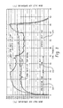
- FIG. 3 is a graphical comparison of drum inlet air temperatures for normal and proposed cycles.
- FIG. 4 is a graphical comparison of drum outlet air temperatures for normal and proposed cycles.
- FIG. 5 is a table of various characteristics illustrating an energy savings of approximately 16.61%.
- FIG. 6 is a graphical representation of typical normal operation of a dryer using 5400 watts of heater power.
- FIG. 7 is a graphical representation similar to FIG. 6 using a heater power of only 2700 watts.
- FIG. 8 is a graphical representation of an alternative drying cycle in which the heater power is curtailed from 5400 watts to 2700 watts part way through the cycle.
- FIG. 9 is graphical representation of yet another alternative where heater power is stepped down in increments from 5400 watts to 2700 watts.
- FIG. 10 is a schematic representation of alternative sources of warm air to reduce energy costs.
- FIG. 11 is a perspective view of an exhaust air heat recovery assembly for use with a dryer.
- FIG. 12 is an enlarged cross-sectional view through a heat exchange component used in FIG. 11 .
- a clothes dryer 110 includes a cabinet or main housing 112 having a first or front panel 114 , a second or rear panel 116 , and a pair of third and fourth, or side, panels 118 , 120 disposed in spaced relation from each other by the front and rear panels, a fifth or bottom panel 122 , and a sixth or top cover 124 .
- a drum or container 126 mounted for rotation around an axis, shown here as a substantially horizontal axis HA.
- Motor 144 rotates the drum about the horizontal axis through a drive means such as pulley 146 and belt 148 .
- the drum is preferably generally cylindrical in shape, and typically has an imperforate outer cylindrical wall 150 and a front flange or wall 160 that has an opening 162 to the drum. Clothing articles or other fabrics are loaded into the drum 126 through the opening 162 . A plurality of tumbling ribs (not shown) are usually provided within the drum 126 to lift the articles and allow the articles to tumble back toward the bottom of the drum as the drum rotates.
- the drum includes a rear wall 170 rotatably supported within the main housing 112 by a suitable fixed bearing.
- the rear wall 170 includes a plurality of openings or holes 172 that receive hot air that has been heated by a heater, such as a combustion chamber 174 and a rear duct 176 .
- the combustion chamber 174 receives ambient air via an inlet 178 .
- the clothes dryer shown in FIG. 1 is a gas dryer, it could just well be an electric dryer without the combustion chamber 174 and the rear duct 176 . Instead in an electric clothes dryer, the air is heated by an electric heating element or heater. Heated air is drawn from the drum by a blower fan 180 which is also advantageously driven by the motor 144 .
- the air passes through a screen filter 182 which traps lint particles in a manner known in the art. As the air passes through the screen filter 182 , it enters a trap duct seal 184 and is passed out of the clothes dryer through an exhaust duct 186 . After the clothing articles have been dried, they are removed from the drum via the opening 162 .
- a temperature sensor 190 and a wetness sensor 192 are often used to predict moisture content and degree of dryness of the clothing articles in the container.
- the temperature sensor 190 senses the temperature of the heated air passing through the screen filter, for example, while the wetness sensor 192 senses the wetness of the clothes in the drum, for example.
- the temperature sensor may be a commercially available sensor such as an Omega Thermocouple-type K, and the wetness sensor may be a commercial off-the-shelf item such as a Parametrics HT-119, although such commercially available components are representative only and one skilled in the art will appreciate that other components that serve these purposes could be used without departing from the scope and intent of the present disclosure.
- the temperature and wetness sensors provide signal representations of the temperature of the heated air, and the wetness of the clothes in the drum, respectively, to a controller 194 .
- the controller 194 is responsive to the temperature sensor and the wetness sensor and, as described below, the controller may then alter operation of the dryer in various ways to save energy over known arrangements (including varying the temperature or flow rate of the air into the drum, varying amounts of re-circulated air, etc.).
- An electric clothes dryer uses hot air, heated by heater and circulated by a blower, for drying clothes. Water in the wet clothes is removed due to a gradient in partial pressures of water vapor between the hot air entering the dryer drum and the air layer adjacent to wet clothes. The higher the wet cloth temperature, the higher the partial pressure gradient and the higher the partial pressure gradient, the more water removal rate from the clothes. Also, there will be two modes of heat transfer between the hot air and the wet clothes; one is the sensible heat transfer from hot air to wet clothes and the other is latent heat of vaporization that is taken from wet clothes. Based on the net effect of these two modes of heat transfer, the clothes temperature will either increase or remain unchanged.
- a typical clothes drying process can be divided into three zones, namely a preheating zone, a latent heat transfer zone and a sensible heat transfer zone (see FIGS. 3 and 4 ).
- a preheating zone wet clothes take the heat from the hot air and the temperature of the clothes increases, as the sensible heat transferred from hot air will be more than the latent heat of vaporization.
- the temperature of wet clothes will increase to reach a plateau (see FIG. 4 ) and the latent heat transfer zone starts.
- the sensible heat transferred from hot air and the latent heat of vaporization will be very close and hence, the wet clothes temperature will remain more or less constant.
- This disclosure is about supplying air for different zones (see FIGS. 3 and 4 ), for example:
- Preheating zone higher inlet air temperature (290° F.) at lower air flow rate (90 CFM), so that the clothes temperature can increase faster;
- Latent Heat Transfer zone slightly lower inlet air temperature (260° F.) and higher airflow rates (140 CFM) than the preheating zone, so that more heat can be transferred without any increase in clothes temperature and hence no damage to the clothes; and
- Sensible heat Zone the lowest inlet air temperature (220° F.), at the highest air flow rates (190 CFM), to ensure that moisture is driven out and the clothes temperature will not increase unnecessarily.
- drum inlet and outlet temperatures are graphed relative to time (in minutes) where the temperature and relative humidity are monitored in a typical drying cycle.
- drum inlet air temperature does not change significantly once it reaches a peak of approximately two hundred forty degrees (240°) F. as represented by plot 200 .
- the drum outlet air temperature 202 increases to approximately one hundred degrees (100°) F. and remains unchanged for a significant period of time, e.g., between about five minutes to about twenty-five minutes into the cycle, and then begins to steadily increase to approximately one hundred thirty degrees (130°) F. about forty-five minutes into the cycle.
- the drum outlet air temperature At the end of the dryer cycle, i.e., between approximately forty-five and fifty minutes as shown in the example of FIG. 2 , the drum outlet air temperature then decreases.
- the dry cycle is a time controlled dry cycle and thereby automatically terminated at the end of the time period, although it will be appreciated that the dry cycle could be based on the sensed outlet temperature increasing to the level of the inlet air temperature and then terminated.
- the rate of heat transfer between hot air and wet clothes can be improved in one of two ways, by increasing the temperature of the entering air, or by increasing the air residence time.
- Increasing the temperature of entering air has the limitation that clothes are potentially damaged if the temperature reaches an overheat condition.
- Increasing the air residence time has the potential to improve the rate of heat transfer while avoiding this limitation.
- air residence time can be increased by reducing airflow rate into the drum. Hot air entering the drum of the dryer transfers heat to the wet clothes and carries the water vapor along with it. During an initial part of the drying cycle, water in the wet clothes absorbs more heat from the hot air without much increase in the temperature of the clothes.
- Increasing the air residence time during this part of the drying cycle results in an increase in the rate of heat transfer between the hot air and the water in the wet clothes. Hence, energy supplied to heat the air is reduced as the airflow rate is reduced.
- a clothes drying cycle can be divided into three relatively distinct divisions or zones, namely a preheating zone 220 , a latent heat zone 222 , and a sensible heat zone 224 .
- a preheating zone initially heat from the heated inlet air is used to heat the damp clothes and the drum that contains them.
- the sensed temperature of the inlet air increases until the air temperature reaches approximately the temperature of the latent heat of vaporization for the moisture remaining in the clothes, at which level the sensed inlet air temperature reaches a temporary plateau.
- the latent heat zone moisture continues to be removed from the clothes until a point is reached where the heat available from the inlet air exceeds that absorbed as latent heat of vaporization and the sensed air temperature begins to gradually increase. This occurrence marks the transition from the latent heat zone to the sensible heat zone.
- the preheat zone comprises approximately the first fifteen minutes of the dry cycle
- the latent heat zone comprises approximately the next 10 minutes of the dry cycle
- the sensible heat zone comprises the balance of the dry cycle.
- plot 230 is representative of a typical or normal drum inlet air temperature that is brought up to approximately two hundred forty degrees (240°) F. in the preheating zone 220 and remains at around two hundred forty degrees (240°) F. through the latent heat zone 222 and sensible heat zone 224 before decreasing at the end of the cycle.
- Plot 232 represents a drying cycle in which the airflow and drum inlet air temperatures are altered throughout the three distinct zones to result in further energy savings.
- the drum inlet air is heated to an elevated temperature of approximately two hundred ninety degrees (290°) F. during a first or preheat portion of the dry cycle (the preheat zone 220 ) and a first airflow rate of approximately ninety (90) CFM is implemented which is less half the typical rate of 190 CFM while in this preheat zone 220 .
- the preheat zone comprises approximately the first fifteen minutes of the drying cycle.
- the drum inlet air temperature is reduced to a second predetermined temperature level of approximately two hundred sixty degrees (260°) F. in this embodiment, while the airflow rate is increased to a second predetermined rate of approximately one hundred forty (140) CFM.
- the controlled reduction in sensed inlet air temperature is time based for this example but could be incorporated in the dryer control software as a look-up table depending on cycle selection, load size and initial moisture content.
- the ten minute period is again selected through experimental data for this example (with recognition that this time period may be different under different conditions). The time intervals would be different for different loads and initial moisture contents. Maximizing the humidity in the exit air is the goal.
- the drum inlet air temperature is further reduced to a third pre-determined temperature (approximately two hundred twenty five degrees) (225° F. in this embodiment) and the air flow rate is still further increased to a third pre-determined rate (approximately one hundred ninety (190) CFM in the exemplary embodiment).
- This lower air temperature at a higher airflow rate, insures that moisture is driven out and that the clothing temperature will not increase unnecessarily.
- the drum outlet air temperature is illustrated in FIG. 4 .
- the drum outlet air temperature begins to increase approximately twenty-five minutes into the cycle. It is determined that this may cause unnecessary wasting of heat energy.
- This is represented by the plot 240 in FIG. 4 .
- the drum outlet air temperature begins to increase after approximately the thirty-fifth minute. This, of course, evidences a savings of heat energy.
- the plot illustrated at 242 in FIG. 4 suggests that the air temperature reaches one hundred degrees) (100° F. faster in the preheating zone with less energy supply when compared to the typical operating cycle.
- the plots 240 and 242 of FIG. 4 represent outlet temperatures that result from operating the dryer in a manner, which produces the inlet temperature plots 230 and 232 of FIG. 3 .
- FIG. 5 compares results 250 of a normal or typical drying cycle, where the airflow rate and power input to heater are constant over the entire cycle, with results 252 of proposed variations of air inlet temperature and airflow rate as described above in connection with FIGS. 3 and 4 .
- a substantially comparable relative moisture content is achieved at the end of a timed drying cycle (total of fifty minutes in the exemplary tests), with a significant energy reduction measured on an electric heater of approximately 0.5 kilowatt hours or an estimated energy savings of approximately 16.61% by implementing the variations in air inlet temperature and airflow rate.
- FIGS. 6-9 are graphical representations of still other methods to improve the energy usage associated with clothes dryers.
- a typical drying operation which serves as a base-line for comparison purposes, may employ an electrical heater that is supplied with a constant heater power of five thousand four hundred (5400) watts (plot 260 ). This correlates to a dryer inlet air temperature of approximately two hundred forty degrees) (240° F. as represented by plot 262 .
- the drum outlet temperature, represented by plot 264 is generally constant over much of the dryer operation and then increases from about ninety degrees (90°) F. to approximately one hundred fifty degrees (150°) F. toward the end of the timed cycle.
- the relative moisture content is shown to decrease over the drying cycle as evidenced by plot 266 .
- the heater power is cut in half, i.e., to approximately two thousand seven hundred (2700) watts as evidenced by graph 280 in FIG. 7 .
- the inlet drum air temperature is still maintained at approximately two hundred forty degrees (240°) F. (plot 282 ), the drum outlet air temperature remains substantially the same (plot 284 ), and the relative moisture content varies slightly over the same time period as represented by plot 286 .
- the relative moisture content curve is slightly different in FIG. 7 than in FIG. 6 , it ultimately reaches approximately the same final level over the same time period and yet the dryer only uses half the heater power at two thousand seven hundred (2700) watts.
- FIG. 8 A variation on the theme is shown in FIG. 8 , where heater power is supplied at the higher wattage level, five thousand four hundred (5400) watts for a predetermined period of the time (about one-half the time period) and then changed to the reduced heater power level of two thousand seven hundred (2700) watts over approximately the last one-half portion of the dryer cycle (plot 290 ).
- the drum inlet air temperature is at approximately two hundred forty degrees (240°) F., as evidenced by plot 292 in FIG. 8
- the outlet air temperature from the drum ranges from approximately ninety degrees (90°) F. to an end value of approximately one hundred forty (140°) F. as represented by plot 294 .
- the relative moisture content also decreases over time, i.e., the clothes dry in response to the heated air and airflow, and the curve is more akin to the relative moisture content curve 286 of FIG. 7 , ultimately reaching what would be deemed a “dry clothes” at the end of the cycle (plot 296 ).
- Still another arrangement is to reduce the inlet air drum temperature by periodically stepping-down the input power as represented in plot line 300 in FIG. 9 .
- the initial wattage is approximately five thousand four hundred (5400) watts, and then reduced by approximately one-quarter about one-third of the way through the cycle, and reduced another one-quarter to the two thousand seven hundred (2700) watt level two-thirds of the way through the cycle.
- the corresponding drum inlet air temperature plot 302 tracks the periodic reduction in the heater power, beginning at a temperature of approximately two hundred forty degrees (240°) F., and reducing to a level around two hundred twenty five degrees (225°) F. approximately one-third of the way through the cycle, and further reducing to about two hundred degrees (200°) F.
- FIGS. 7-9 demonstrate that reducing the amount of electrical heater power results in energy savings over what is deemed a typical drying cycle as exhibited in FIG. 6 of a constant heater power over the entire dryer cycle time period.
- the heater power can be reduced as the outlet temperature increases. This will, in turn, cause less wasted heat and save energy over the drying cycle.
- Monitoring either the outlet dryer temperature or the dampness of the load via the sensor rods also permits the inlet thermistor to be set in response thereto to reduce the heater power, or the fan speed, or both. Again, this will cause less wasted heat over the cycle and result in an energy savings.
- the controller monitors outlet and inlet air temperatures and, in response, reacts with different wattage outputs.
- FIG. 10 represents another potential energy savings feature.
- a fan 320 is located in the attic 322 that includes an attic vent 324 , or possibly outside the building or home. Warm air is drawn through air filter 326 disposed in the attic into the dryer housing from an outside source such as the attic or outside air. This eliminates the need to pull warm air from inside the house to the dryer. Air from the dryer is then directed outside the house. This arrangement will also reduce the energy needed to heat the air from ambient temperature.
- Such an energy savings kit would include, for example, a variable speed fan, pressure switches 330 , temperature sensors 332 , and associated duct work 334 .
- the remotely located fan will be controlled by the pressure switch and the dryer controller uses the remote temperature sensor as an input to determine whether air should be blown into the cabinet from the remote outside source. It will also be appreciated that taking heat out of the attic will result in an energy savings for the house, not just an improvement in savings associated with reduced dryer energy. For example, in the summer months, the air conditioner load could be reduced with a lower attic temperature.
- FIGS. 11 and 12 illustrate a multi-tube transition duct assembly 340 that may be used to efficiently transfer heat away from internal ducting, which can then be reintroduced into the inlet of the dryer.
- the heat recovery assembly 340 may include a module or housing 342 that receives a multi-tube transition duct 344 associated with the blower 346 which receives exhaust air from the dryer.
- air vented from the dryer reaches the blower 346 at blower inlet 348 , and is then directed into dryer passages or tubes 350 that direct the elevated temperature air in the passages 350 toward outside vent 352 .
- the individual passages 350 are received within a shell 354 having an inlet 356 that permits air from inside the dryer cabinet, for example at a temperature of approximately eighty (80°) F., to pass over external surfaces of the individual dryer passages 350 toward the outlet 358 and includes a blower 360 driven by a motor (not shown) to draw the air into the inlet 356 of the shell and across the dryer passages where the heat exchange results in an increase of air temperature of approximately twenty degrees (20°) F. to about one hundred degrees (100°) F., where the heat recovered air is then directed toward the heater intake 362 of the dryer.
- residual condensate may collect at drain tube 370 and directed toward a drain, while the remaining exhaust air is directed toward the outside vent as represented at 352.
Landscapes
- Engineering & Computer Science (AREA)
- Textile Engineering (AREA)
- Control Of Washing Machine And Dryer (AREA)
- Detail Structures Of Washing Machines And Dryers (AREA)
Abstract
Description
3) Sensible heat Zone: the lowest inlet air temperature (220° F.), at the highest air flow rates (190 CFM), to ensure that moisture is driven out and the clothes temperature will not increase unnecessarily.
Claims (23)
Priority Applications (1)
| Application Number | Priority Date | Filing Date | Title |
|---|---|---|---|
| US13/162,109 US8991068B2 (en) | 2011-06-16 | 2011-06-16 | Energy efficient cycle for clothes dryer |
Applications Claiming Priority (1)
| Application Number | Priority Date | Filing Date | Title |
|---|---|---|---|
| US13/162,109 US8991068B2 (en) | 2011-06-16 | 2011-06-16 | Energy efficient cycle for clothes dryer |
Publications (2)
| Publication Number | Publication Date |
|---|---|
| US20120317832A1 US20120317832A1 (en) | 2012-12-20 |
| US8991068B2 true US8991068B2 (en) | 2015-03-31 |
Family
ID=47352543
Family Applications (1)
| Application Number | Title | Priority Date | Filing Date |
|---|---|---|---|
| US13/162,109 Active 2033-11-15 US8991068B2 (en) | 2011-06-16 | 2011-06-16 | Energy efficient cycle for clothes dryer |
Country Status (1)
| Country | Link |
|---|---|
| US (1) | US8991068B2 (en) |
Families Citing this family (9)
| Publication number | Priority date | Publication date | Assignee | Title |
|---|---|---|---|---|
| EP2738303A1 (en) * | 2012-11-28 | 2014-06-04 | Electrolux Home Products Corporation N.V. | A method for controlling a drying cycle of a laundry dryer |
| US9322127B2 (en) * | 2013-05-22 | 2016-04-26 | Whirlpool Corporation | Method of operating a home appliance |
| CN104233735B (en) * | 2013-06-21 | 2018-02-23 | 海尔集团公司 | A kind of heat pump clothes dryer and clothes-drying method |
| US20180038042A1 (en) * | 2015-03-02 | 2018-02-08 | Arcelik Anonim Sirketi | Heat pump type laundry dryer and method for controlling the same |
| US10138590B2 (en) * | 2015-03-20 | 2018-11-27 | Whirlpool Corporation | Method for drying laundry in a laundry treating appliance |
| WO2016200155A1 (en) * | 2015-06-08 | 2016-12-15 | 주식회사 고영테크놀러지 | Humid air forming device, inspection device comprising same, and inspection method |
| CN105483997A (en) * | 2015-11-20 | 2016-04-13 | 李家海 | Axial air intake type energy-saving industrial clothes dryer |
| CN109944046B (en) * | 2019-04-16 | 2020-07-28 | 珠海格力电器股份有限公司 | Control method and control device of clothes drying equipment and clothes drying equipment |
| CN113609660B (en) * | 2021-07-27 | 2024-03-15 | 江苏科技大学 | A numerical simulation method to predict the heat and mass transfer rules of clothes in the dryer |
Citations (9)
| Publication number | Priority date | Publication date | Assignee | Title |
|---|---|---|---|---|
| US3833205A (en) * | 1972-02-02 | 1974-09-03 | Midland Ross Corp | Apparatus for eliminating water vapor from processed air |
| US4231166A (en) * | 1979-10-09 | 1980-11-04 | General Electric Company | Automatic control for a clothes dryer |
| US4397101A (en) | 1981-09-10 | 1983-08-09 | General Electric Company | Automatic dryer control |
| US4649654A (en) * | 1985-03-29 | 1987-03-17 | Hitachi, Ltd. | Apparatus for controlling electric clothes dryer and method therefor |
| US5666739A (en) * | 1994-08-02 | 1997-09-16 | Krueger; Waldemar | Energy conservation coupler |
| US5899005A (en) | 1997-03-13 | 1999-05-04 | General Electric Company | System and method for predicting the dryness of clothing articles |
| US6122840A (en) | 1998-11-18 | 2000-09-26 | General Electric Company | Systems and methods for determining drying time for a clothes dryer |
| US7426791B2 (en) | 2005-02-09 | 2008-09-23 | Martin Mack V | Energy saving device for clothes dryer and clothes dryer system comprising same |
| US7478486B2 (en) | 2000-05-02 | 2009-01-20 | General Electric Company | System and method for controlling a dryer appliance |
-
2011
- 2011-06-16 US US13/162,109 patent/US8991068B2/en active Active
Patent Citations (9)
| Publication number | Priority date | Publication date | Assignee | Title |
|---|---|---|---|---|
| US3833205A (en) * | 1972-02-02 | 1974-09-03 | Midland Ross Corp | Apparatus for eliminating water vapor from processed air |
| US4231166A (en) * | 1979-10-09 | 1980-11-04 | General Electric Company | Automatic control for a clothes dryer |
| US4397101A (en) | 1981-09-10 | 1983-08-09 | General Electric Company | Automatic dryer control |
| US4649654A (en) * | 1985-03-29 | 1987-03-17 | Hitachi, Ltd. | Apparatus for controlling electric clothes dryer and method therefor |
| US5666739A (en) * | 1994-08-02 | 1997-09-16 | Krueger; Waldemar | Energy conservation coupler |
| US5899005A (en) | 1997-03-13 | 1999-05-04 | General Electric Company | System and method for predicting the dryness of clothing articles |
| US6122840A (en) | 1998-11-18 | 2000-09-26 | General Electric Company | Systems and methods for determining drying time for a clothes dryer |
| US7478486B2 (en) | 2000-05-02 | 2009-01-20 | General Electric Company | System and method for controlling a dryer appliance |
| US7426791B2 (en) | 2005-02-09 | 2008-09-23 | Martin Mack V | Energy saving device for clothes dryer and clothes dryer system comprising same |
Also Published As
| Publication number | Publication date |
|---|---|
| US20120317832A1 (en) | 2012-12-20 |
Similar Documents
| Publication | Publication Date | Title |
|---|---|---|
| US8991068B2 (en) | Energy efficient cycle for clothes dryer | |
| CN104870710B (en) | Operate the method for heat pump cloth drying machine and heat pump cloth drying machine or heat pump washing machine with drying function | |
| EP2333141B1 (en) | Clothes dryer | |
| US9091014B2 (en) | Clothing dryer and control method thereof | |
| US9677218B2 (en) | Method for controlling a motor of a laundry dryer | |
| KR101351042B1 (en) | Controll method of the laundry treating machine | |
| EP2935687B1 (en) | A method for controlling a laundry drying machine and a corresponding laundry drying machine | |
| CN104919109B (en) | Method of operating heat pump laundry dryer and heat pump laundry dryer or heat pump washing machine with drying function | |
| CN102713047B (en) | Clothes dryer and control method thereof | |
| JP4976965B2 (en) | Clothes dryer | |
| EP2922993A1 (en) | A method for controlling a laundry dryer with a variable drum rotation speed and a variable fan rotation speed | |
| US11060236B2 (en) | Dryer appliance and method of operating the same based on the relative humidity of drum exit air | |
| JP7303973B2 (en) | bathroom heater dryer | |
| CN102677441A (en) | Heat pump clothes dryer control method and heat pump clothes dryer | |
| KR102679836B1 (en) | Control Method for Drying Machine | |
| US10072375B2 (en) | Method for drying clothes in a drier and a moisture estimation control to obtain an automatic cycle termination | |
| JP2004159859A (en) | Clothes dryer | |
| JP6466093B2 (en) | Clothes dryer | |
| KR101168888B1 (en) | Method for compensating electric power interrruption in clothes dryer | |
| CN206495075U (en) | A kind of heat pump type clothes dryer | |
| KR101210725B1 (en) | Clothes drier and control method of clothes drier | |
| JP7727435B2 (en) | Drum-type washer-dryer | |
| WO2025222669A1 (en) | Control method and apparatus for laundry treatment device, and storage medium and device | |
| CN120830223A (en) | clothes dryer | |
| JP2025117386A (en) | Dryers and sterilizers |
Legal Events
| Date | Code | Title | Description |
|---|---|---|---|
| AS | Assignment |
Owner name: GENERAL ELECTRIC COMPANY, NEW YORK Free format text: ASSIGNMENT OF ASSIGNORS INTEREST;ASSIGNORS:LAKKINENI, VENKAT RAMPRASAD;ZENTNER, MARTIN MITCHELL;ANIKHINDI, SANJAY MANOHAR;AND OTHERS;SIGNING DATES FROM 20110610 TO 20110614;REEL/FRAME:026454/0808 |
|
| FEPP | Fee payment procedure |
Free format text: PAYOR NUMBER ASSIGNED (ORIGINAL EVENT CODE: ASPN); ENTITY STATUS OF PATENT OWNER: LARGE ENTITY |
|
| STCF | Information on status: patent grant |
Free format text: PATENTED CASE |
|
| AS | Assignment |
Owner name: HAIER US APPLIANCE SOLUTIONS, INC., DELAWARE Free format text: ASSIGNMENT OF ASSIGNORS INTEREST;ASSIGNOR:GENERAL ELECTRIC COMPANY;REEL/FRAME:038950/0504 Effective date: 20160606 |
|
| MAFP | Maintenance fee payment |
Free format text: PAYMENT OF MAINTENANCE FEE, 4TH YEAR, LARGE ENTITY (ORIGINAL EVENT CODE: M1551) Year of fee payment: 4 |
|
| MAFP | Maintenance fee payment |
Free format text: PAYMENT OF MAINTENANCE FEE, 8TH YEAR, LARGE ENTITY (ORIGINAL EVENT CODE: M1552); ENTITY STATUS OF PATENT OWNER: LARGE ENTITY Year of fee payment: 8 |