US8985638B2 - Stacked washer slip joint seal - Google Patents
Stacked washer slip joint seal Download PDFInfo
- Publication number
- US8985638B2 US8985638B2 US13/440,121 US201213440121A US8985638B2 US 8985638 B2 US8985638 B2 US 8985638B2 US 201213440121 A US201213440121 A US 201213440121A US 8985638 B2 US8985638 B2 US 8985638B2
- Authority
- US
- United States
- Prior art keywords
- washers
- slip joint
- joint according
- inner diameter
- flat shim
- Prior art date
- Legal status (The legal status is an assumption and is not a legal conclusion. Google has not performed a legal analysis and makes no representation as to the accuracy of the status listed.)
- Active, expires
Links
Images


Classifications
-
- F—MECHANICAL ENGINEERING; LIGHTING; HEATING; WEAPONS; BLASTING
- F16—ENGINEERING ELEMENTS AND UNITS; GENERAL MEASURES FOR PRODUCING AND MAINTAINING EFFECTIVE FUNCTIONING OF MACHINES OR INSTALLATIONS; THERMAL INSULATION IN GENERAL
- F16L—PIPES; JOINTS OR FITTINGS FOR PIPES; SUPPORTS FOR PIPES, CABLES OR PROTECTIVE TUBING; MEANS FOR THERMAL INSULATION IN GENERAL
- F16L21/00—Joints with sleeve or socket
- F16L21/02—Joints with sleeve or socket with elastic sealing rings between pipe and sleeve or between pipe and socket, e.g. with rolling or other prefabricated profiled rings
- F16L21/03—Joints with sleeve or socket with elastic sealing rings between pipe and sleeve or between pipe and socket, e.g. with rolling or other prefabricated profiled rings placed in the socket before connection
-
- F—MECHANICAL ENGINEERING; LIGHTING; HEATING; WEAPONS; BLASTING
- F01—MACHINES OR ENGINES IN GENERAL; ENGINE PLANTS IN GENERAL; STEAM ENGINES
- F01N—GAS-FLOW SILENCERS OR EXHAUST APPARATUS FOR MACHINES OR ENGINES IN GENERAL; GAS-FLOW SILENCERS OR EXHAUST APPARATUS FOR INTERNAL-COMBUSTION ENGINES
- F01N13/00—Exhaust or silencing apparatus characterised by constructional features
- F01N13/18—Construction facilitating manufacture, assembly, or disassembly
- F01N13/1805—Fixing exhaust manifolds, exhaust pipes or pipe sections to each other, to engine or to vehicle body
- F01N13/1827—Sealings specially adapted for exhaust systems
-
- F—MECHANICAL ENGINEERING; LIGHTING; HEATING; WEAPONS; BLASTING
- F16—ENGINEERING ELEMENTS AND UNITS; GENERAL MEASURES FOR PRODUCING AND MAINTAINING EFFECTIVE FUNCTIONING OF MACHINES OR INSTALLATIONS; THERMAL INSULATION IN GENERAL
- F16L—PIPES; JOINTS OR FITTINGS FOR PIPES; SUPPORTS FOR PIPES, CABLES OR PROTECTIVE TUBING; MEANS FOR THERMAL INSULATION IN GENERAL
- F16L51/00—Expansion-compensation arrangements for pipe-lines
Definitions
- the present invention relates to a slip joint with a stacked washer seal for use in an exhaust system of an internal combustion engines.
- Slip joints are designed to allow exhaust system parts to move with respect to one another. Such movement may be due to thermal expansion and/or movement from different parts of the vehicle.
- the joint permits movement between the exhaust system parts so that they are not damaged and the parts they are connected to, such as the engine, is not damaged. This permitted movement is especially important in heavy duty diesel engines due to the increased length of the exhaust manifold.
- Another known method utilizes split rings between two parts.
- the rings are expensive, precision parts that require special hardware machining. Further, they only result in average sealing performance between the parts. Additionally, the quality that provides them some sealing capability also increases friction between the mated parts, thus impeding the sliding function of the joint.
- bellows may provide a good seal, but the material can be expensive and its installation is inconvenient. At the least they are known to be bulky and heavy. Further, there are concerns about the durability of the bellows material. Lastly, bellows only seal against the escape of hot gases after the gases have traveled through the joint itself. This exposes the joint to high temperatures that can damage hardware and permit exhaust particulates an opportunity to become stuck in the joint. Particulates that become stuck in the joint may impede the function of the joint, and prevent movement of the parts with respect to one another as discussed above.
- the present invention is directed toward a slip joint with a stacked washer seal having a first male part and a second female part.
- the female part has a small inner diameter portion and a large inner diameter portion. The diameter portions are unitary with one another and directly beside one another.
- the male part comprises substantially constant inner and outer diameters, with the inner diameter being substantially equal to the small inner diameter portion of the female part.
- the male part comprises a ring located on the outer diameter.
- a gap is located between the male part and the female part.
- At least two washers and at least one flat shim are located in the gap. Each washer and each flat shim have a first side, a second side, a first end and a second end.
- the first side of a first washer abuts an end of the male part or a carrier, and the second side of the first washer is in direct contact with a first side of the flat shim.
- the second side of the flat shim is in direct contact with the first side of a second washer.
- the second side of the second washer is in direct contact with a first side of a second flat shim or an abutting end of the female part.
- the carrier has a tubular portion and an upstanding flange portion.
- the tubular portion has a substantially constant inner and outer diameter.
- the flange portion is unitary with the tubular portion and extends radially outward from the tubular portion at approximately 90 degrees.
- FIG. 1 is a cross-sectional view of a slip joint and the stacked washer seal
- FIG. 2 is a top view of a washer
- FIG. 3 is a cross-sectional view of the washer in FIG. 2 along line 3 - 3 ;
- FIG. 4 is a cross-sectional view of another embodiment of FIG. 1 ;
- FIG. 5 is a cross-sectional view of another embodiment of FIG. 1 ;
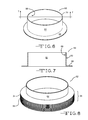
- FIG. 6 is a perspective view of the carrier
- FIG. 7 is a cross-sectional view of the carrier along line 8 - 8 ;
- FIG. 8 is a perspective view of the carrier with stacked washer seal
- FIG. 9 is an enlarged cross-sectional view of the stacked washer seal and carrier
- FIG. 10 is a cross-sectional view of the carrier with stacked washer seal
- FIG. 11 is a partial cross-sectional view of washers with a flat shim
- FIG. 12 is a partial cross-sectional view of different washers with a flat shim
- FIG. 13 is a partial cross-sectional view of different washers with a flat shim.
- FIG. 14 is a cross-sectional view of a slip joint.
- a slip joint 10 is comprised of two parts, a first male part 12 and a second female part 14 as depicted in FIG. 1 . It is desirable for the parts 12 , 14 to be able to selectively move with respect to one another.
- the parts 12 , 14 may be tubular in nature, each with a hollow interior. It is preferred that the interiors are in fluid communication with one another.
- the parts 12 , 14 may be, by way of example, parts of an exhaust system (not shown) for a vehicle.
- the parts 12 , 14 communicate exhaust gases from an internal combustion engine (not shown), such as a diesel engine, away from the engine.
- the female part 14 has a small inner diameter portion 16 and a large inner diameter portion 18 .
- the two portions 16 , 18 are unitary with one another and directly beside one another.
- the male part 12 may be substantially constant in its inner 20 and outer 22 diameters.
- the male inner diameter 20 may be the same or substantially equal to said small inner diameter portion 16 of the female part 12 .
- the male outer diameter 22 is larger than the female smaller inner diameter 16 , but substantially equal to the female larger inner diameter portion 18 .
- a ring 24 may be located on the outer diameter 22 of the male part 12 .
- the ring 24 is designed to function as a stop. More particularly, the ring 24 may selectively abut an end surface 26 of the female part 14 to prevent the male part 12 from moving too far with respect to the female part 14 .
- a gap 28 is located between an end 30 of the male part 12 and a transition area 32 between the small inner diameter portion 16 and the large inner diameter portion 18 of the female part 14 .
- At least two washers 34 a , 34 b , and at least one flat shim 36 act as a seal 38 and may be located in the gap 28 , as depicted in FIGS. 1 and 5 .
- the washer 34 may be Bellville washers.
- a Bellville washer is a type of spring shaped like a washer. It has a frusto-conical shape, i.e.; in the depicted embodiment the area about the center and the center opening extends away at an angle that is not planar with the center. This feature gives the washer 34 a spring characteristic.
- Some properties of Belleville washers include: high fatigue life, better space utilization, low creep tendency, and high load capacity with a small spring deflection.
- each washer 34 comprises a first side 40 , a second side 42 , a first end 44 and a second end 46 .
- each flat shim 36 comprises a first side 48 , a second side 50 , a first end 52 and a second end 54 .
- the second side 42 a of the first washer 34 a is in direct contact with a first side 48 a of a flat shim 36 a .
- the second side 50 a of the flat shim 36 a is in direct contact with the first side 40 b of a second washer 34 b
- the second side 42 b of the second washer 34 b may be in direct contact with a first side 48 b of a second flat shim 36 b .
- This configuration continues for as many washers 34 and shims 36 are required to create the seal 38 needed for a particular application.
- the seal 38 abuts the end 30 of the male part 12 and the transition area 32 of the female part 14 .
- a plurality of washers 34 are arranged in a series configuration, where each washer 34 is separated and supported by a flat shim 36 , as depicted in FIG. 9 .
- the number and orientation of the washers 34 and flat shims 36 may be changed from the depicted embodiment to customize the seal 38 for particular applications. For example, greater or fewer washers 34 may be used and they may be in series, in parallel or in combinations of series and parallel.
- multiple Belleville washers 34 may be stacked to modify the spring constant or amount of deflection. Stacking in the same direction will add the spring constant in parallel, creating a stiffer joint (with the same deflection). Stacking in an alternating direction is the same as adding springs in series, resulting in a lower spring constant and greater deflection. Mixing and matching directions allow a specific spring constant and deflection capacity to be designed.
- first end 44 of a washer 34 and the first end 52 of a flat shim 36 may be in direct contact with each other.
- second end 46 of a washer 34 and the second end 54 of a flat shim 36 may be in direct contact with each other.
- a selective gap 58 may be located between the second end 46 of a washer 34 and the second end 54 of a flat shim 36
- a second selective gap 60 may be located between the first end 44 of a washer 34 and the first end 52 of a flat shim 36 .
- the seal 38 is located in the gap 28 between the male and the female parts 12 , 14 . It can be appreciated that when the slip joint 10 expands, the seal 38 compresses and the sealing stress points increase. Placement of the seal 38 in this location prevents exhaust gases from escaping through the gap 28 without disrupting the slip function of the slip joint 10 .
- the seal 38 blocks hot exhaust gases from entering the slip joint 10 and causing oxidation damage to the larger inner diameter portion 18 of the female part 14 and the outer diameter 22 of the male part 12 .
- a bound or oxidized slip joint is no longer a slip joint and can lead to further motion-induced damage to engine hardware and fasteners.
- This interior placement of the seal 38 also reduces the clutter around the exhaust system and allows for more flexibility when designing the layout of other system components. Interior placement also eliminates the concern of a seal causing injuries while servicing the engine.
- FIG. 4 An alternative embodiment for placement of the seal 38 is depicted in FIG. 4 .
- the seal 38 is located on the outer diameter 22 of the male part 12 . Specifically, it is located between the ring 24 on the outer diameter 22 of the male part 12 and the end 26 of the female part 14 . This location allows for the use of lower-cost metal alloys due to the lower operating temperatures and convective cooling that is available through the joint parts.
- FIG. 5 Yet another embodiment is depicted in the FIG. 5 .
- the seal 38 is located similarly to FIG. 1 , but the seal 38 is accompanied with and supported by a carrier 62 .
- the carrier 62 as depicted in FIGS. 6 and 7 is comprised of a tubular portion 64 and an upstanding flange portion 66 .
- the tubular portion 64 has a substantially constant inner diameter 68 and outer diameter 70 .
- the flange portion 66 is unitary with the tubular portion 64 and extends radially outward from the tubular portion 64 at approximately 90 degrees.
- the carrier 62 may be solid metal or have notches designed to allow for a variety of manufacturing processes.
- the carrier 62 may be made of 304 stainless steel.
- the seal 38 may be held in place with the aid of the carrier 62 and installed on the interior of the slip joint, as depicted in FIG. 5 .
- the carrier 62 as shown in FIG. 8 assists in properly locating the seal 38 and it functions as a hot gas barrier to route the bulk of the gas past the seal 38 and from entering the slip joint area.
- the carrier 62 aids in installation of the seal 38 by holding the washers 34 and shims 36 together in the correct orientations, as shown in FIGS. 8 and 10 .
- the seal 38 is located around the tubular portion 64 of the carrier 62 .
- the seal 38 has the same, or approximately the same, outer diameter as the flange portion 66 of the carrier 62 .
- the inner diameter 72 of the washers 34 and the inner diameter 74 of the shims are substantially equal to the outer diameter 70 of the tubular portion 64 of the carrier 62 , as depicted in FIG. 9 .
- the carrier 62 provides a means to locate the washers 34 and shims 36 with respect to their internal diameters 72 , 74 , therefore making the design more flexible and allowing for the installation in slip joints with wider machining tolerances. As depicted in FIG. 5 , the seal 38 abuts the flange portion 66 of the carrier 62 and the transition area 32 of the female part 14 .
- FIG. 11 The figure depicts a partial cross section of washers 34 a, b and a shim 36 a . Here the layers are shown with some concentricity shift. Any shifting in the layers reduces the seals 38 ability to prevent exhaust gases from escaping between the two parts 12 , 14 .
- the washers 34 a, b may have flattened edges.
- the flattened edges may be located either at the first end 44 a, b or the second end 46 a, b of the washers 34 a, b .
- the flattened edges allow the washers 34 a, b to maintain excellent sealing contact during concentricity shifts.
- two washers 34 a, b are shown with flattened edges and a curved feature to prevent concentricity shifts.
- the flattened edges may be located either at the first end 44 a, b or the second end 46 a, b of the washers 34 a, b with the curved end being located on the opposite end.
- shifting is reduced due to the flattened end of one washer abutting the curved end of another washer.
- the washer designs shown feature many advantages over the prior art.
- the designs provide for a very high recovery, low load design that optimizes performance in high thermal growth conditions.
- the seal 38 functions, in part, by deploying an axial load against hardware stops and/or ends. This axle loading forces the seal 38 against the stops to prevent any leakage of gas from escaping between the two parts 12 , 14 .
- FIG. 14 depicts one embodiment of the parts 12 , 14 with existing stops 24 , 26 , 30 , 32 .
- the stops 24 , 26 , 30 , 32 prevent the male part 12 from moving too far with respect to the female part 14 .
- the stops may be any shape. They may also be located anywhere on the parts so as to adjust the mating relationship between the parts, as may be required by each application. Alternatively, the stops may or may not be a part of the parts to be joined.
Landscapes
- Engineering & Computer Science (AREA)
- General Engineering & Computer Science (AREA)
- Mechanical Engineering (AREA)
- Chemical & Material Sciences (AREA)
- Combustion & Propulsion (AREA)
- Gasket Seals (AREA)
Abstract
Description
Claims (15)
Priority Applications (1)
| Application Number | Priority Date | Filing Date | Title |
|---|---|---|---|
| US13/440,121 US8985638B2 (en) | 2011-04-07 | 2012-04-05 | Stacked washer slip joint seal |
Applications Claiming Priority (2)
| Application Number | Priority Date | Filing Date | Title |
|---|---|---|---|
| US201161472696P | 2011-04-07 | 2011-04-07 | |
| US13/440,121 US8985638B2 (en) | 2011-04-07 | 2012-04-05 | Stacked washer slip joint seal |
Publications (2)
| Publication Number | Publication Date |
|---|---|
| US20130093181A1 US20130093181A1 (en) | 2013-04-18 |
| US8985638B2 true US8985638B2 (en) | 2015-03-24 |
Family
ID=48085476
Family Applications (1)
| Application Number | Title | Priority Date | Filing Date |
|---|---|---|---|
| US13/440,121 Active 2032-07-15 US8985638B2 (en) | 2011-04-07 | 2012-04-05 | Stacked washer slip joint seal |
Country Status (1)
| Country | Link |
|---|---|
| US (1) | US8985638B2 (en) |
Families Citing this family (3)
| Publication number | Priority date | Publication date | Assignee | Title |
|---|---|---|---|---|
| US9422857B2 (en) | 2014-12-17 | 2016-08-23 | Caterpillar Inc. | Exhaust nozzle tip device and system |
| CN204785197U (en) * | 2015-05-27 | 2015-11-18 | 何远东 | Flexible fluid hose |
| DE102020119002B3 (en) * | 2020-07-17 | 2021-12-30 | Poloplast Gmbh & Co. Kg | Pipe socket |
Citations (18)
| Publication number | Priority date | Publication date | Assignee | Title |
|---|---|---|---|---|
| US2407745A (en) * | 1944-08-09 | 1946-09-17 | Jacobson Franz | Rotary joint |
| US2534123A (en) | 1944-05-04 | 1950-12-12 | Cook Electric Co | Method of making metal bellows |
| US3692337A (en) * | 1970-09-04 | 1972-09-19 | Avica Corp | Flexible coupling |
| JPS5833722A (en) | 1981-08-20 | 1983-02-28 | Matsushita Electric Ind Co Ltd | Control valve |
| JPS5985320A (en) | 1982-11-08 | 1984-05-17 | Hitachi Ltd | Spool supplying and extracting device in strip rolling installation |
| JPS6223517A (en) | 1985-07-23 | 1987-01-31 | Yamaha Motor Co Ltd | Connecting device for exhaust pipe of engine |
| DE4136799A1 (en) | 1991-11-08 | 1993-05-13 | Josef Fey Lamellenringe | Lamellar ring seal for exhaust pipe joint - has wave contour spring ring supporting lamellar single seal ring |
| JPH05231574A (en) | 1992-02-19 | 1993-09-07 | Nippon Gasket Kk | Sealing device of tube connection part |
| DE19718406A1 (en) | 1997-04-30 | 1998-11-05 | Josef Fey Lamellenringe | Sealing for axial compensator of exhaust pipes for internal combustion engines |
| DE20012679U1 (en) | 2000-07-21 | 2000-12-21 | Köthener Spezialdichtungen GmbH, 06369 Wülknitz | Spring-loaded sealing system |
| JP2001021077A (en) | 1999-07-07 | 2001-01-26 | Hitachi Metals Ltd | Insertion type pipe joint |
| US6220605B1 (en) | 1998-07-14 | 2001-04-24 | Caterpillar Inc. | Slip joint connection for engine exhaust system |
| US6860487B2 (en) | 2002-09-24 | 2005-03-01 | Honda Giken Kogyo Kabushiki Kaisha | Insertable gasket and inserting structure |
| US6902204B2 (en) * | 2002-11-26 | 2005-06-07 | Microflex, Inc. | Exhaust vibration decoupling connector with locked liner tubes |
| US7134648B1 (en) | 2002-01-22 | 2006-11-14 | Rode John E | Interlocking disc spring assemblies and adjustable interlocking disc spring assemblies |
| US20080012296A1 (en) | 2005-08-26 | 2008-01-17 | Cummins Inc. | Exhaust system slip joint |
| US7331612B2 (en) | 2004-03-26 | 2008-02-19 | Honeywell International, Inc. | Low profile tension style flexible joint |
| JP5231574B2 (en) | 2008-01-28 | 2013-07-10 | リフレクティブ エックス−レイ オプティクス エルエルシー | Optical alignment system and alignment method for X-ray imaging by X-ray imaging |
-
2012
- 2012-04-05 US US13/440,121 patent/US8985638B2/en active Active
Patent Citations (18)
| Publication number | Priority date | Publication date | Assignee | Title |
|---|---|---|---|---|
| US2534123A (en) | 1944-05-04 | 1950-12-12 | Cook Electric Co | Method of making metal bellows |
| US2407745A (en) * | 1944-08-09 | 1946-09-17 | Jacobson Franz | Rotary joint |
| US3692337A (en) * | 1970-09-04 | 1972-09-19 | Avica Corp | Flexible coupling |
| JPS5833722A (en) | 1981-08-20 | 1983-02-28 | Matsushita Electric Ind Co Ltd | Control valve |
| JPS5985320A (en) | 1982-11-08 | 1984-05-17 | Hitachi Ltd | Spool supplying and extracting device in strip rolling installation |
| JPS6223517A (en) | 1985-07-23 | 1987-01-31 | Yamaha Motor Co Ltd | Connecting device for exhaust pipe of engine |
| DE4136799A1 (en) | 1991-11-08 | 1993-05-13 | Josef Fey Lamellenringe | Lamellar ring seal for exhaust pipe joint - has wave contour spring ring supporting lamellar single seal ring |
| JPH05231574A (en) | 1992-02-19 | 1993-09-07 | Nippon Gasket Kk | Sealing device of tube connection part |
| DE19718406A1 (en) | 1997-04-30 | 1998-11-05 | Josef Fey Lamellenringe | Sealing for axial compensator of exhaust pipes for internal combustion engines |
| US6220605B1 (en) | 1998-07-14 | 2001-04-24 | Caterpillar Inc. | Slip joint connection for engine exhaust system |
| JP2001021077A (en) | 1999-07-07 | 2001-01-26 | Hitachi Metals Ltd | Insertion type pipe joint |
| DE20012679U1 (en) | 2000-07-21 | 2000-12-21 | Köthener Spezialdichtungen GmbH, 06369 Wülknitz | Spring-loaded sealing system |
| US7134648B1 (en) | 2002-01-22 | 2006-11-14 | Rode John E | Interlocking disc spring assemblies and adjustable interlocking disc spring assemblies |
| US6860487B2 (en) | 2002-09-24 | 2005-03-01 | Honda Giken Kogyo Kabushiki Kaisha | Insertable gasket and inserting structure |
| US6902204B2 (en) * | 2002-11-26 | 2005-06-07 | Microflex, Inc. | Exhaust vibration decoupling connector with locked liner tubes |
| US7331612B2 (en) | 2004-03-26 | 2008-02-19 | Honeywell International, Inc. | Low profile tension style flexible joint |
| US20080012296A1 (en) | 2005-08-26 | 2008-01-17 | Cummins Inc. | Exhaust system slip joint |
| JP5231574B2 (en) | 2008-01-28 | 2013-07-10 | リフレクティブ エックス−レイ オプティクス エルエルシー | Optical alignment system and alignment method for X-ray imaging by X-ray imaging |
Also Published As
| Publication number | Publication date |
|---|---|
| US20130093181A1 (en) | 2013-04-18 |
Similar Documents
| Publication | Publication Date | Title |
|---|---|---|
| US6279965B1 (en) | Pipe joint | |
| US8500172B2 (en) | Double cover-center cushion decoupler | |
| JP5735432B2 (en) | Liquid-cooled exhaust valve assembly | |
| EP1046002B1 (en) | Nested bridge seal | |
| JP5478502B2 (en) | Sealed segment and sealed segment structure | |
| JP3884511B2 (en) | Multi-degree-of-freedom expansion joint | |
| EP2900972B1 (en) | Panel support hanger for a turbine engine | |
| US6312022B1 (en) | Pipe joint and seal | |
| US8500131B2 (en) | Exhaust manifold gasket | |
| US5611577A (en) | Bellows sealed ball joint and method of forming | |
| US20100072710A1 (en) | Gas Turbine Seal | |
| US20080100059A1 (en) | Axial and Radial Play and Angle Compensation of a Tolerating Pipe Connection | |
| US20160238137A1 (en) | Seal runner | |
| US8985638B2 (en) | Stacked washer slip joint seal | |
| JP2005061596A (en) | Sealing device | |
| US20160333765A1 (en) | Pipe connection arrangement for connecting two pipe ends, in particular two pipe ends arranged in an exhaust line of a combustion engine | |
| US20080308170A1 (en) | Air duct having flexible bellows | |
| CN106352189A (en) | Compensator, in particular for motor vehicle applications | |
| EP2681480B1 (en) | Pipe unit in a conduit for a gaseous medium | |
| US5098133A (en) | Tube coupling with swivelable piston | |
| US10598211B2 (en) | Spherical bearing sleeve configured with one or more discrete collars | |
| CN110226025A (en) | High-temperature resistant tube for air-air aftercooler is to collector mechanical splice | |
| US11788655B2 (en) | Tube coupling | |
| EP1674686A1 (en) | Pipe joint, gasket and method for obtaining the joint | |
| WO2013006132A1 (en) | Connection between two pipes in a pipeline |
Legal Events
| Date | Code | Title | Description |
|---|---|---|---|
| AS | Assignment |
Owner name: DANA AUTOMOTIVE SYSTEMS GROUP, LLC, OHIO Free format text: ASSIGNMENT OF ASSIGNORS INTEREST;ASSIGNORS:OXENKNECHT, ERNEST;PLUNKETT, TOM;POPIELAS, FRANK;AND OTHERS;SIGNING DATES FROM 20120405 TO 20120410;REEL/FRAME:028094/0034 |
|
| STCF | Information on status: patent grant |
Free format text: PATENTED CASE |
|
| MAFP | Maintenance fee payment |
Free format text: PAYMENT OF MAINTENANCE FEE, 4TH YEAR, LARGE ENTITY (ORIGINAL EVENT CODE: M1551); ENTITY STATUS OF PATENT OWNER: LARGE ENTITY Year of fee payment: 4 |
|
| AS | Assignment |
Owner name: CITIBANK, N.A., NEW YORK Free format text: SECURITY AGREEMENT SUPPLEMENT;ASSIGNORS:DANA HEAVY VEHICLE SYSTEMS GROUP, LLC;DANA LIMITED;DANA AUTOMOTIVE SYSTEMS GROUP, LLC;AND OTHERS;REEL/FRAME:052459/0224 Effective date: 20200416 Owner name: CITIBANK, N.A., NEW YORK Free format text: SECURITY AGREEMENT (BRIDGE);ASSIGNORS:DANA HEAVY VEHICLE SYSTEMS GROUP, LLC;DANA LIMITED;DANA AUTOMOTIVE SYSTEMS GROUP, LLC;AND OTHERS;REEL/FRAME:052459/0001 Effective date: 20200416 |
|
| AS | Assignment |
Owner name: DANA AUTOMOTIVE SYSTEMS GROUP, LLC, OHIO Free format text: RELEASE BY SECURED PARTY;ASSIGNOR:CITIBANK, N.A.;REEL/FRAME:053309/0686 Effective date: 20200619 Owner name: DANA LIMITED, OHIO Free format text: RELEASE BY SECURED PARTY;ASSIGNOR:CITIBANK, N.A.;REEL/FRAME:053309/0686 Effective date: 20200619 Owner name: DANA HEAVY VEHICLE SYSTEMS GROUP, LLC, OHIO Free format text: RELEASE BY SECURED PARTY;ASSIGNOR:CITIBANK, N.A.;REEL/FRAME:053309/0686 Effective date: 20200619 Owner name: FAIRFIELD MANUFACTURING COMPANY, INC., OHIO Free format text: RELEASE BY SECURED PARTY;ASSIGNOR:CITIBANK, N.A.;REEL/FRAME:053309/0686 Effective date: 20200619 |
|
| MAFP | Maintenance fee payment |
Free format text: PAYMENT OF MAINTENANCE FEE, 8TH YEAR, LARGE ENTITY (ORIGINAL EVENT CODE: M1552); ENTITY STATUS OF PATENT OWNER: LARGE ENTITY Year of fee payment: 8 |