EP1674686A1 - Pipe joint, gasket and method for obtaining the joint - Google Patents
Pipe joint, gasket and method for obtaining the joint Download PDFInfo
- Publication number
- EP1674686A1 EP1674686A1 EP05027580A EP05027580A EP1674686A1 EP 1674686 A1 EP1674686 A1 EP 1674686A1 EP 05027580 A EP05027580 A EP 05027580A EP 05027580 A EP05027580 A EP 05027580A EP 1674686 A1 EP1674686 A1 EP 1674686A1
- Authority
- EP
- European Patent Office
- Prior art keywords
- pipe
- segment
- section
- gasket
- female
- Prior art date
- Legal status (The legal status is an assumption and is not a legal conclusion. Google has not performed a legal analysis and makes no representation as to the accuracy of the status listed.)
- Granted
Links
Images

Classifications
-
- F—MECHANICAL ENGINEERING; LIGHTING; HEATING; WEAPONS; BLASTING
- F01—MACHINES OR ENGINES IN GENERAL; ENGINE PLANTS IN GENERAL; STEAM ENGINES
- F01N—GAS-FLOW SILENCERS OR EXHAUST APPARATUS FOR MACHINES OR ENGINES IN GENERAL; GAS-FLOW SILENCERS OR EXHAUST APPARATUS FOR INTERNAL COMBUSTION ENGINES
- F01N13/00—Exhaust or silencing apparatus characterised by constructional features ; Exhaust or silencing apparatus, or parts thereof, having pertinent characteristics not provided for in, or of interest apart from, groups F01N1/00 - F01N5/00, F01N9/00, F01N11/00
- F01N13/18—Construction facilitating manufacture, assembly, or disassembly
- F01N13/1805—Fixing exhaust manifolds, exhaust pipes or pipe sections to each other, to engine or to vehicle body
- F01N13/1827—Sealings specially adapted for exhaust systems
-
- F—MECHANICAL ENGINEERING; LIGHTING; HEATING; WEAPONS; BLASTING
- F16—ENGINEERING ELEMENTS AND UNITS; GENERAL MEASURES FOR PRODUCING AND MAINTAINING EFFECTIVE FUNCTIONING OF MACHINES OR INSTALLATIONS; THERMAL INSULATION IN GENERAL
- F16L—PIPES; JOINTS OR FITTINGS FOR PIPES; SUPPORTS FOR PIPES, CABLES OR PROTECTIVE TUBING; MEANS FOR THERMAL INSULATION IN GENERAL
- F16L21/00—Joints with sleeve or socket
- F16L21/02—Joints with sleeve or socket with elastic sealing rings between pipe and sleeve or between pipe and socket, e.g. with rolling or other prefabricated profiled rings
-
- F—MECHANICAL ENGINEERING; LIGHTING; HEATING; WEAPONS; BLASTING
- F16—ENGINEERING ELEMENTS AND UNITS; GENERAL MEASURES FOR PRODUCING AND MAINTAINING EFFECTIVE FUNCTIONING OF MACHINES OR INSTALLATIONS; THERMAL INSULATION IN GENERAL
- F16L—PIPES; JOINTS OR FITTINGS FOR PIPES; SUPPORTS FOR PIPES, CABLES OR PROTECTIVE TUBING; MEANS FOR THERMAL INSULATION IN GENERAL
- F16L21/00—Joints with sleeve or socket
- F16L21/08—Joints with sleeve or socket with additional locking means
-
- F—MECHANICAL ENGINEERING; LIGHTING; HEATING; WEAPONS; BLASTING
- F16—ENGINEERING ELEMENTS AND UNITS; GENERAL MEASURES FOR PRODUCING AND MAINTAINING EFFECTIVE FUNCTIONING OF MACHINES OR INSTALLATIONS; THERMAL INSULATION IN GENERAL
- F16L—PIPES; JOINTS OR FITTINGS FOR PIPES; SUPPORTS FOR PIPES, CABLES OR PROTECTIVE TUBING; MEANS FOR THERMAL INSULATION IN GENERAL
- F16L23/00—Flanged joints
- F16L23/02—Flanged joints the flanges being connected by members tensioned axially
- F16L23/024—Flanged joints the flanges being connected by members tensioned axially characterised by how the flanges are joined to, or form an extension of, the pipes
- F16L23/026—Flanged joints the flanges being connected by members tensioned axially characterised by how the flanges are joined to, or form an extension of, the pipes by welding
-
- F—MECHANICAL ENGINEERING; LIGHTING; HEATING; WEAPONS; BLASTING
- F16—ENGINEERING ELEMENTS AND UNITS; GENERAL MEASURES FOR PRODUCING AND MAINTAINING EFFECTIVE FUNCTIONING OF MACHINES OR INSTALLATIONS; THERMAL INSULATION IN GENERAL
- F16L—PIPES; JOINTS OR FITTINGS FOR PIPES; SUPPORTS FOR PIPES, CABLES OR PROTECTIVE TUBING; MEANS FOR THERMAL INSULATION IN GENERAL
- F16L23/00—Flanged joints
- F16L23/16—Flanged joints characterised by the sealing means
- F16L23/18—Flanged joints characterised by the sealing means the sealing means being rings
Definitions
- the present invention relates, in general, to joints for pipelines traversed by fluids in the liquid or gaseous state.
- the present invention relates to joints for pipeline segments to be used in the automotive industry to discharge exhaust gases (exhaust pipelines or pipes) of internal combustion engines.
- Cup junctions are generally used in cases in which, in use, even high fluid losses are allowed, since heretofore no satisfactory solutions (e.g. adequate gaskets) had been identified to assure the seal of this type of junctions.
- cup junctions are used on the exhaust pipelines of motor vehicles due to their low cost but, because of the growing need to contain emissions, these junctions have been relegated in ever more limited areas of the vehicle, e.g. downstream of any catalytic devices in order not to distort the measurement by probes associated to such catalytic devices for pollution control.
- a cup joint comprises a base pipe (male pipe) and a pie having an appropriately widened end (female or female end) able to receive a determined portion of the male pipe.
- the prior art teaches that, to avoid the subsequent extraction of the male pipe from the female in the axial direction, it is advantageous to effect two or more cuts on the female in the axial direction in order to allow, subsequently to installation, by means of an external collar, the narrowing of the diameter of the female end and its forcing on the outer diameter of the male pipe.
- the known document proposes a cup joint in which the female end comprises a conical segment and a window; the window is configured in such a way that a collar having a section inclined in the direction of axial mounting can be inserted into it.
- the male pipe according to the known document, comprises, in the terminal part, a conical segment and, at the window, a groove,
- the collar is pressed in the window in such a way as to cause the axial movement of the male pipe in the female until the respective conical segments of the male pipe and of the female are approached.
- the Applicant notes that although the known joint assures a good axial locking, it does not assures, due to defects or coarse tolerances, a good seal against fluid leakage since, in use, only a small percentage of forces is discharged orthogonally to the axial locking forces.
- the prior art also teaches the use of flanged joints, in particular, for applications pertaining to the exhaust pipelines of motor vehicles.
- the pipe segments are joined by means of a pair of flanges appropriately welded or fastened to the ends of the pipe segments,
- junctions are mounted by pressing the flanges together with mechanical means such as screws, springs, etc., in order to mutually approach the flanges and, consequently, the pipe segments as much as possible.
- flanged junctions generally assure a good axial locking, in fact they have similar problems to those noted for cup joints with respect to fluid sealing, for the coupling between the flanges and consequently between the pipes is not always adequate, for example due to defects or coarse machining tolerances.
- various solutions of flanged joints have been proposed and, in particular, of gaskets or sealing materials to be used to assure a good seal by such joints.
- patent document EP 1 267 049 B1 proposes, in particular, a gasket with toroidal development for flanged joints to be used for the passage of the exhaust gases of internal combustion engines.
- the proposed gasket comprises, in addition to a graphite ring encapsulated in a sheet of metal with toroidal development, an additional sheet able to be held associated to one of the two flanges when mounting the joint.
- the object of the present invention is to solve the problems of the prior art, listed above.
- the present invention further relates to a method for manufacturing the joint structure according to the invention as well as a type of gasket to be applied in the joint
- the claims are an integral part of the technical teaching provided herein with regard to the invention.
- the tubes at the end comprise a female segment and a male segment with conical sections with differentiated inclination.
- the joint structure if of the cup type or of the flange cup.
- a joint or a joint structure in a first embodiment, of the cup type 10, comprises a first end (female end or female) 12 of a first pipe segment or pipe (female segment) 20, e.g. made of stainless steel or other material able not to be corroded by the fluids that flow through it, e.g. acid condensation, and a second end (male end or male) 14 of a second pipe segment (male pipe) 40, e.g, made of the same material as the same pipe 20, able to be joined by axial pressure and locked, e.g. by means of a known clamp 25.
- the female end 12 comprises, in a preferred embodiment, a first area (area AF) with substantially conical section with an angle that diverges, relative to the axis of the pipe, ranging, for example, between 5° and 15°.
- area AF a first area
- This shape is able to assure, in use, the seal of the joint 10.
- the area AF has such a surface finish as to be free of coarse defects such as scratches, machining prints etc.
- the female 12 also comprises, in the preferred embodiment, a second area (area BF) with sufficiently ample inner section to allow the insertion of the male 14, as will be explained in detail below.
- the female 12 comprises, lastly, in the preferred embodiment, a third area (area CF) having a slightly smaller diameter than the diameter of the area BF.
- in the area CF are provided two or more known cuts in the axial direction.
- the area CF is capable both of allowing a good centring of the pipes 20 and 40, as said area CF, as is readily understandable to those skilled in the art, is the last one to be inserted during the mounting phase, and of assuring a good mechanical tightening through the clamp 25.
- the male end 14 comprises, in the preferred embodiment, a first area (area AM) with substantially conical section with a converging angle relative to the axis of the pipe, ranging, for example, between 4° and 14° and with a preferable value of about 10°.
- the expression "substantially conical” means that the cross section of the male or female pipe may be not only circular but also of another kind, e.g. elliptic or flattened elliptic and that consequently the areas AF and AM are substantially conical compatibly with the cross section of the pipe.
- the conical section (area AF) of the female 12 is inclined with an angle that is preferably 1°-5° greater than the inclination of the corresponding area AM of the male 14.
- low inclination differences will be preferable between area AF and area AM in the case of low axial load when mounting a high inclination differences in the opposite case.
- the inclination values indicated respectively for the area AF and AM can vary both according to the axial mounting force available and according to the section and the dimensions of the pipes, for equal materials, without altering the principle that the inclination of the area AF of the female 12 is greater than that of the area AM of the male 14.
- the values provided in the example correspond to preferable values for exhaust pipes to be used in the automotive and engine industry.
- the male end 14 also comprises a second area (area BM), preferably having its outer section slightly smaller than the outer section of the female 12 in the area BF, to facilitate the insertion of the male 14 into the female 12.
- area BM second area
- the male end 14 comprises, lastly, one or more gaskets (gasket) 42, preferably pre-mounted in the area AM, with annular shape or type.
- the gasket 42 is pre-mounted by forcing, in known fashion, in the axial direction on the male 14, manually or with a tool, the annular shaped gasket 42 in such a way that it can be planted on the surface of the area AM of the male and come in contact, during the mounting phase, with the corresponding area AF of the female 12.
- the gasket 42 is of the deformable type and the deformability is obtained by using, for example if the joint 10 is used in the automotive and engine industry, soft metallic material, such as copper or aluminium, choosing, for example according to the maximum operating temperature: aluminium for temperatures up to 450°C and the copper for higher temperatures (up to about 800°C).
- the gasket 42 may have differently shaped sections according to the axial load available when mounting the joint 10.
- the section will be solid 45 (Fig. 3a-3d) for high axial loads, e.g. 50 kg or greater, or hollow 46 (Fig. 3e-3f) for lower loads.
- shapes with edges are capable of having, initially, contacts with the surface of the male 14 in very restricted area in such a way that, when forced, there are, as is understandable to a person skilled in the art, high specific pressures and consequent considerable deformation of the gasket 42; as a result of such deformations, the contact of the gasket with the pipes 20 and 40 in the joint 10, after "copying” any imperfections in the construction of the pipes, rapidly extends in the section of the gasket giving lift to the gasket 42 and thereby assuring the necessary thrust to provide a seal against fluids on the walls of the pipes 20 and 40 in the segments AF and AM.
- gaskets 42 with hollow section 46 hard but elastic materials can be used for the gasket 42, e.g. stainless steel with low thickness (maximum 0.4 mm).
- hollow section 46 advantageously, allows a good radial deformability and, modifying for example the thickness of the material used for the gasket 42, it is possible to obtain a residual elasticity useful to compensate for possible movements of the joint 10 as a result, for example, of heat excursions or mechanical stress variations during use.
- a spiral gasket 46 is proposed and, in particular, in Fig. 3f a gasket 46 is proposed with "S" or double “S” mirror shaped hollow section, which is well suited to provide the elasticity characteristics listed above.
- a joint or joint structure is illustrated of the type with flanges 100 comprising a first end (flanged female element or female) 112, e.g. welded, in known fashion, to the end of a first pipe segment or pipe 120, and a second end (flanged male element or male) 114, e.g. welded in known fashion to the end of a second pipe segment or pipe 140.
- Both the female element 112 and the male element 114, in addition to the pipes 120 and 140 are obtained with materials that are substantially equivalent to those described for the cup joint 10.
- Both the female element 112 and the male element 114 are able to be joined, in known fashion, for example, by means of appropriate nuts 125a and screws 125b, known in themselves, arranged in axis with the pipes 120 and 140 to be joined.
- nuts and the screws can be replaced by other devices able to perform equivalent functions, e.g. bolts, etc.
- the female 112 comprises, similarly to what has already been described, an area (area AF) with substantially conical section with equivalent characteristics to those described for the cup joint 10. In this case, too, the shape of the female element 112 is adapted to assure, in use, the seal of the joint 100.
- the area AF of the female 112 has a surface finish of the type described above.
- the male 114 comprises, similarly to what has already been described, an area (area AM) with substantially conical section with equivalent characteristics to those already described for the cup joint 10.
- the conical section (area AF) of the female 112 is inclined with a greater angle than that of the area AM of the male 114 and, preferably with equivalent characteristics to those described for the cup joint 10.
- the male 114 also comprises, similarly to what has already been described, one or more gaskets (gasket) 42, preferably pre-mounted in the area AM, having equivalent shape, dimensions and characteristics to those already described for the cup joint 10.
- the joint action of the two conical shapes is susceptible to causing the crushing of the gasket between the walls with different conicity of the female 12 and of the male 14, also with a reduced axial fitting load and it will prevent the gasket from sliding relative to both pipes, 20 and 40.
- the combined action of the two conical shapes is able to generate, according to the force applied, a component of forces prevalently in the transverse direction to the axial component such as to facilitate the sealing function of the gasket 42 with respect to fluids.
- the reduced difference between the outer section of the male pipe 40 and that of the female pipe 20 in the area CF will allow, for example, solidly to fasten the female 1'2 to the male 14 by means of the clamp 25.
- the axial fitting load is applied by means of the closing nuts 125a to assure the fastening of the flanges.
- the force that can be applied by means of the nuts 125a is greater than in the previous case (even a few tons)
- the centring function between the flanges is delegated to the same areas AF and AM.
- the joint in the various embodiments, allows the described gaskets to obtain a good radial seal and to eliminate or reduce any plays due to shape errors or coarse tolerances, without, however, markedly increasing the mounting stress.
Abstract
Description
- The present invention relates, in general, to joints for pipelines traversed by fluids in the liquid or gaseous state.
- In particular, the present invention relates to joints for pipeline segments to be used in the automotive industry to discharge exhaust gases (exhaust pipelines or pipes) of internal combustion engines.
- In the prior art, in particular in the automotive industry, use of cup or flange joints or junctions is known to join exhaust gas pipeline segments.
- Cup junctions are generally used in cases in which, in use, even high fluid losses are allowed, since heretofore no satisfactory solutions (e.g. adequate gaskets) had been identified to assure the seal of this type of junctions.
- In particular, cup junctions are used on the exhaust pipelines of motor vehicles due to their low cost but, because of the growing need to contain emissions, these junctions have been relegated in ever more limited areas of the vehicle, e.g. downstream of any catalytic devices in order not to distort the measurement by probes associated to such catalytic devices for pollution control.
- In general, a cup joint comprises a base pipe (male pipe) and a pie having an appropriately widened end (female or female end) able to receive a determined portion of the male pipe.
- In the case of motor vehicles, installation is accomplished manually, applying an axial force to the male pipe and operating under the vehicle, so it is advantageous to leave considerable "play" between the diameter of the male pipe and the female in order to require a small force for installation.
- The prior art teaches that, to avoid the subsequent extraction of the male pipe from the female in the axial direction, it is advantageous to effect two or more cuts on the female in the axial direction in order to allow, subsequently to installation, by means of an external collar, the narrowing of the diameter of the female end and its forcing on the outer diameter of the male pipe.
- In this type of prior art, fluid loss occurs through the "play" between female diameter and male pipe diameter (circumferential play) and through the innermost part of the cuts, because they cannot be deformed by the outer collar.
- The patent document published with N. JP09-133279 discloses a type of cup joint that attempts to solve both the problem of a complete locking and that of an effective seal of the joint.
- The known document proposes a cup joint in which the female end comprises a conical segment and a window; the window is configured in such a way that a collar having a section inclined in the direction of axial mounting can be inserted into it. The male pipe, according to the known document, comprises, in the terminal part, a conical segment and, at the window, a groove,
- During installation, the collar is pressed in the window in such a way as to cause the axial movement of the male pipe in the female until the respective conical segments of the male pipe and of the female are approached.
- According to the document, to assure a good seal, at the conical segments is interposed such a sealing material that, as the conical segments approach, breaks up into small pieces in order to occupy the space between the male and female pipe.
- The Applicant notes that this kind of joint is particularly complex and difficult to mount to the point of making its use and convenience particularly limited.
- Moreover, the Applicant notes that although the known joint assures a good axial locking, it does not assures, due to defects or coarse tolerances, a good seal against fluid leakage since, in use, only a small percentage of forces is discharged orthogonally to the axial locking forces.
- The prior art also teaches the use of flanged joints, in particular, for applications pertaining to the exhaust pipelines of motor vehicles.
- In flanged junctions, generally more expensive than cup junctions, the pipe segments are joined by means of a pair of flanges appropriately welded or fastened to the ends of the pipe segments,
- These types of junctions are mounted by pressing the flanges together with mechanical means such as screws, springs, etc., in order to mutually approach the flanges and, consequently, the pipe segments as much as possible.
- Although flanged junctions generally assure a good axial locking, in fact they have similar problems to those noted for cup joints with respect to fluid sealing, for the coupling between the flanges and consequently between the pipes is not always adequate, for example due to defects or coarse machining tolerances. To overcome said problems, various solutions of flanged joints have been proposed and, in particular, of gaskets or sealing materials to be used to assure a good seal by such joints.
- For example, patent document EP 1 267 049 B1 proposes, in particular, a gasket with toroidal development for flanged joints to be used for the passage of the exhaust gases of internal combustion engines.
- The proposed gasket comprises, in addition to a graphite ring encapsulated in a sheet of metal with toroidal development, an additional sheet able to be held associated to one of the two flanges when mounting the joint.
- The Applicant observes that this type of joint too, although it assures a good axial locking, does not assure, due to defects or coarse tolerances, a good seal against fluid leakage because, in use, only a low percentage of forces is discharged orthogonally to the axial locking forces.
- The Applicant essentially observes that prior art joints, both cup and flange type, do not seem to exhibit satisfactory characteristics with regard to sealing against the leakage of fluids, in the liquid or gaseous state, which flow through them.
- The object of the present invention is to solve the problems of the prior art, listed above.
- According to the present invention, this object is achieved by means of a joint structure having the characteristics set out in the claims that follow.
- The present invention further relates to a method for manufacturing the joint structure according to the invention as well as a type of gasket to be applied in the joint The claims are an integral part of the technical teaching provided herein with regard to the invention.
- According to a preferred embodiment, in the joint structure the tubes at the end comprise a female segment and a male segment with conical sections with differentiated inclination.
- According to an additional characteristic of the present invention, the joint structure if of the cup type or of the flange cup.
- This and other characteristics of the present invention will become readily apparent from the following description of a preferred embodiment, provided by way of non limiting example with the aid of the accompanying figures, in which:
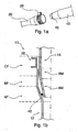
- Fig. 1a and 1b show a first embodiment of the joint according to the invention;
- Fig. 2 shows a second embodiment of the joint according to the invention; and
- Fig. 3a to 3f show examples of gaskets usable in the joints of Fig. 1a, 1 b and 2.
- With reference to Fig.1 a and 1b, a joint or a joint structure, in a first embodiment, of the
cup type 10, comprises a first end (female end or female) 12 of a first pipe segment or pipe (female segment) 20, e.g. made of stainless steel or other material able not to be corroded by the fluids that flow through it, e.g. acid condensation, and a second end (male end or male) 14 of a second pipe segment (male pipe) 40, e.g, made of the same material as thesame pipe 20, able to be joined by axial pressure and locked, e.g. by means of a knownclamp 25. - The
female end 12 comprises, in a preferred embodiment, a first area (area AF) with substantially conical section with an angle that diverges, relative to the axis of the pipe, ranging, for example, between 5° and 15°. This shape, as will be described in detail below, is able to assure, in use, the seal of thejoint 10. Preferably, the area AF has such a surface finish as to be free of coarse defects such as scratches, machining prints etc. - The female 12 also comprises, in the preferred embodiment, a second area (area BF) with sufficiently ample inner section to allow the insertion of the
male 14, as will be explained in detail below. - The female 12 comprises, lastly, in the preferred embodiment, a third area (area CF) having a slightly smaller diameter than the diameter of the area BF.
- In additional embodiments, in the area CF are provided two or more known cuts in the axial direction.
- The area CF, so configured, is capable both of allowing a good centring of the
pipes clamp 25. - The
male end 14 comprises, in the preferred embodiment, a first area (area AM) with substantially conical section with a converging angle relative to the axis of the pipe, ranging, for example, between 4° and 14° and with a preferable value of about 10°. - In the present description, use of the expression "substantially conical" means that the cross section of the male or female pipe may be not only circular but also of another kind, e.g. elliptic or flattened elliptic and that consequently the areas AF and AM are substantially conical compatibly with the cross section of the pipe. In accordance with one of the characteristics of the present invention, the conical section (area AF) of the
female 12 is inclined with an angle that is preferably 1°-5° greater than the inclination of the corresponding area AM of themale 14. - For example, low inclination differences will be preferable between area AF and area AM in the case of low axial load when mounting a high inclination differences in the opposite case.
- As is understandable for a person skilled in the art, the inclination values indicated respectively for the area AF and AM can vary both according to the axial mounting force available and according to the section and the dimensions of the pipes, for equal materials, without altering the principle that the inclination of the area AF of the
female 12 is greater than that of the area AM of themale 14. - The values provided in the example correspond to preferable values for exhaust pipes to be used in the automotive and engine industry.
- The
male end 14 also comprises a second area (area BM), preferably having its outer section slightly smaller than the outer section of the female 12 in the area BF, to facilitate the insertion of themale 14 into thefemale 12. - In other embodiments, to facilitate the insertion of the
male 14 into the female 12, it is possible that only one between the area BF and the corresponding area BM is modified with respect to the inner or outer section of therespective pipes - The
male end 14 comprises, lastly, one or more gaskets (gasket) 42, preferably pre-mounted in the area AM, with annular shape or type. - In the preferred embodiment, the
gasket 42 is pre-mounted by forcing, in known fashion, in the axial direction on themale 14, manually or with a tool, the annularshaped gasket 42 in such a way that it can be planted on the surface of the area AM of the male and come in contact, during the mounting phase, with the corresponding area AF of thefemale 12. - Preferably, the
gasket 42 is of the deformable type and the deformability is obtained by using, for example if thejoint 10 is used in the automotive and engine industry, soft metallic material, such as copper or aluminium, choosing, for example according to the maximum operating temperature: aluminium for temperatures up to 450°C and the copper for higher temperatures (up to about 800°C). - The
gasket 42 may have differently shaped sections according to the axial load available when mounting thejoint 10. - For example, the section will be solid 45 (Fig. 3a-3d) for high axial loads, e.g. 50 kg or greater, or hollow 46 (Fig. 3e-3f) for lower loads.
- In the case of
gaskets 42 withsolid section 45, preferably, in accordance to additional possible characteristics of the present invention, in Figures 3a-3c shapes with solid section are proposed with a plurality of edges, e.g. shapes with quadrangular section, such as square, rhomboidal or rectangular. Advantageously, shapes with edges are capable of having, initially, contacts with the surface of the male 14 in very restricted area in such a way that, when forced, there are, as is understandable to a person skilled in the art, high specific pressures and consequent considerable deformation of thegasket 42; as a result of such deformations, the contact of the gasket with thepipes gasket 42 and thereby assuring the necessary thrust to provide a seal against fluids on the walls of thepipes - In the case of
gaskets 42 withhollow section 46, hard but elastic materials can be used for thegasket 42, e.g. stainless steel with low thickness (maximum 0.4 mm). - Use of the
hollow section 46, advantageously, allows a good radial deformability and, modifying for example the thickness of the material used for thegasket 42, it is possible to obtain a residual elasticity useful to compensate for possible movements of the joint 10 as a result, for example, of heat excursions or mechanical stress variations during use. - Preferably, in accordance with additional possible characteristics of the present invention, in Fig. 3e a
spiral gasket 46 is proposed and, in particular, in Fig. 3f agasket 46 is proposed with "S" or double "S" mirror shaped hollow section, which is well suited to provide the elasticity characteristics listed above. - In accordance with a second embodiment and with reference to Fig. 2, a joint or joint structure is illustrated of the type with flanges 100 comprising a first end (flanged female element or female) 112, e.g. welded, in known fashion, to the end of a first pipe segment or
pipe 120, and a second end (flanged male element or male) 114, e.g. welded in known fashion to the end of a second pipe segment orpipe 140. - Both the
female element 112 and themale element 114, in addition to thepipes - Both the
female element 112 and themale element 114 are able to be joined, in known fashion, for example, by means ofappropriate nuts 125a and screws 125b, known in themselves, arranged in axis with thepipes - Naturally, as is readily understandable to a person skilled in the art, in additional embodiments the nuts and the screws can be replaced by other devices able to perform equivalent functions, e.g. bolts, etc.
- The female 112 comprises, similarly to what has already been described, an area (area AF) with substantially conical section with equivalent characteristics to those described for the cup joint 10. In this case, too, the shape of the
female element 112 is adapted to assure, in use, the seal of the joint 100. - Preferably, the area AF of the female 112 has a surface finish of the type described above.
- The male 114 comprises, similarly to what has already been described, an area (area AM) with substantially conical section with equivalent characteristics to those already described for the cup joint 10.
- In accordance with one of the characteristics of the present invention, the conical section (area AF) of the female 112 is inclined with a greater angle than that of the area AM of the male 114 and, preferably with equivalent characteristics to those described for the cup joint 10.
- The male 114 also comprises, similarly to what has already been described, one or more gaskets (gasket) 42, preferably pre-mounted in the area AM, having equivalent shape, dimensions and characteristics to those already described for the cup joint 10.
- According to the method for mounting the joint, e.g. in the case of cup joint 10 (Fig. 1a. Fig. 1b) once the
gasket 42 is positioned on themale end 14, a force is applied, substantially in axial direction, to thepipe 40 in such a way as to thrust thegasket 42 against the conical wall of the female 12. - The joint action of the two conical shapes is susceptible to causing the crushing of the gasket between the walls with different conicity of the female 12 and of the male 14, also with a reduced axial fitting load and it will prevent the gasket from sliding relative to both pipes, 20 and 40. In particular, the combined action of the two conical shapes is able to generate, according to the force applied, a component of forces prevalently in the transverse direction to the axial component such as to facilitate the sealing function of the
gasket 42 with respect to fluids. - Lastly, once the
male pipe 40 is inserted into thefemale pipe 20, preferably, the reduced difference between the outer section of themale pipe 40 and that of thefemale pipe 20 in the area CF will allow, for example, solidly to fasten the female 1'2 to the male 14 by means of theclamp 25. - The same effect of crushing the
gasket 42 can be obtained, by means of the flanged joint 100 (Fig. 2), as described in the second embodiment. - In accorctance with said additional embodiment, the axial fitting load is applied by means of the
closing nuts 125a to assure the fastening of the flanges. In particular, since the force that can be applied by means of the nuts 125a is greater than in the previous case (even a few tons), it will be possible to obtain, thanks to the different conicity of themale flange 114 and of thefemale flange 112, a strong deformation of thegasket 42 and a consequent marked mutual approach of the flanges, with the effect of compensate, for example, large shape errors or coarse tolerances of the flanges, In accordance with this second embodiment, the centring function between the flanges is delegated to the same areas AF and AM. - The joint, in the various embodiments, allows the described gaskets to obtain a good radial seal and to eliminate or reduce any plays due to shape errors or coarse tolerances, without, however, markedly increasing the mounting stress.
- Obvious modifications or variants to the above description are possible, in the dimensions, shapes, materials, components, as well as in the details of the illustrated construction and of the method of operation without departing from the scope of the invention as specified by the claims that follow.
Claims (10)
- A joint structure for pipelines traversed by fluid comprising- a first end (12, 112) of a first pipe (20);- a second end (14, 114) of a second pipe (40) able to be fastened in axis with said first pipe (20) by applying a determined mounting force along a direction corresponding to the direction of said fastening axis;characterised in that- said first end (12, 112) comprises- at least a female segment (AF) having substantially conical section with a predetermined inclination angle;and in that- said second end (14, 114) comprises- at least a male segment (AM) having a substantially conical section with a smaller inclination angle than said predetermined female segment (AF); and- at least one gasket (42) fitted on said male segment (AM) and able to apply a sealing force with a direction that is prevalently transverse to the direction of said mounting force.
- A joint structure as claimed in claim 1 wherein said predetermined inclination angle of said female segment (AF) ranges between 5° and 15° sexagesimal degrees.
- A joint structure as claimed in claim 1 wherein said at least one gasket (42) has a section selected in the group formed by- circular solid section;- quadrangular solid section;- "S" shaped hollow section;- mirror double "S" shaped hollow section;- a section that is a combination of said sections.
- A joint structure as daimed in claim 1 through 3 wherein said first end (12) and said second end (14) are configured to obtain a cup joint (10).
- A joint structure as claimed in claim 4 wherein- said first end and said second end comprise, upstream of said respective female segment (AF) and said respective male segment (AM), at least one insertion area (BF, BM) having a predetermined difference between the inner section of said first pipe (20) and the outer section of said second pipe (40); and wherein- said first end and said second end comprise, upstream of said insertion area, at least a centring area (CF) wherein the difference between the inner section of said first pipe (20) and the outer section of said second pipe (40) is smaller than said predetermined difference in section of said insertion area.
- A joint structure as claimed in claim 1 through 3 wherein said first end (112) and said second end (114) are configured to obtain a flanged joint (100).
- A joint structure as claimed in claim 6 wherein said flanged joint (100) comprises- at least a pair of fastening devices (125a, 125b) associated to said first and second end (112, 114) and configured to assure the fastening of said first end (112) to said second end (114).
- A gasket for joints of pipes traversed by fluids, wherein at least one end (12, 112, 14, 114) of at least one pipe (20, 40) comprises at least one segment (AM) with a substantially conical section, and wherein said gasket is adapted to be fitted on said segment (AM) by means of a determined fitting stress, characterised in that- said gasket has a section comprising a plurality of edges; and in that- at least one of said edges is able to exercise on said segment (AM), based on said fitting stress, a specific pressure having a prevalent radial component to said pipe.
- Method for obtaining a joint structure for pipelines traversed by fluids wherein a first pipe (20) has a first end (12, 112) having at least one female segment (AF), wherein a second pipe (40) has a second end (14, 114) having at least one male segment (AM) and wherein said second pipe (40) is able to be fastened in axis to said first pipe (20); characterised by the steps of:- applying to said at least one female segment (AF) a substantially conical with a predetermined inclination angle;- applying to said at least one male segment a substantially conical section with a smaller inclination angle than said predetermined inclination angle of said female segment (AF);- mounting on said at least one male segment (AM) at least one gasket for generating by means of said gasket, when mounting, a sealing force with a direction that is prevalently transverse to the direction of fastening.
- Internal combustion engine comprising at least one joint structure as claimed in claims 1 through 7.
Applications Claiming Priority (1)
| Application Number | Priority Date | Filing Date | Title |
|---|---|---|---|
| IT000898A ITTO20040898A1 (en) | 2004-12-23 | 2004-12-23 | JOINT STRUCTURE FOR PIPE ROUTES FROM FLUIDS, GASKETS AND RELATIVE REALIZATION METHOD |
Publications (2)
| Publication Number | Publication Date |
|---|---|
| EP1674686A1 true EP1674686A1 (en) | 2006-06-28 |
| EP1674686B1 EP1674686B1 (en) | 2008-01-30 |
Family
ID=35734011
Family Applications (1)
| Application Number | Title | Priority Date | Filing Date |
|---|---|---|---|
| EP05027580A Not-in-force EP1674686B1 (en) | 2004-12-23 | 2005-12-16 | Pipe joint, gasket and method for obtaining the joint |
Country Status (4)
| Country | Link |
|---|---|
| EP (1) | EP1674686B1 (en) |
| AT (1) | ATE385282T1 (en) |
| DE (1) | DE602005004591T2 (en) |
| IT (1) | ITTO20040898A1 (en) |
Cited By (5)
| Publication number | Priority date | Publication date | Assignee | Title |
|---|---|---|---|---|
| DE102008058958A1 (en) | 2008-11-25 | 2010-05-27 | Daimler Ag | Tubes connection arrangement for use in fuel cell system of drive device of vehicle, has tubes rotatable relative to each other around tube middle axis when flanges of tubes are connected with each other |
| CN106555912A (en) * | 2017-02-07 | 2017-04-05 | 兴化市苏星金属制品有限公司 | A kind of board-like W.N flange |
| CN106764159A (en) * | 2017-02-07 | 2017-05-31 | 兴化市苏星金属制品有限公司 | A kind of hubbed clip-on-welding flange |
| CN109764200A (en) * | 2019-03-18 | 2019-05-17 | 天津海科瑞德科技有限公司 | A kind of special-shaped flange being tightly connected firmly for pipeline |
| CN112031923A (en) * | 2020-08-07 | 2020-12-04 | 中国北方发动机研究所(天津) | Two-stage supercharging system connection mode |
Families Citing this family (2)
| Publication number | Priority date | Publication date | Assignee | Title |
|---|---|---|---|---|
| CN101806379B (en) * | 2010-04-20 | 2011-09-07 | 航天晨光股份有限公司 | Rotary flange |
| CN106764160A (en) * | 2017-02-07 | 2017-05-31 | 兴化市苏星金属制品有限公司 | A kind of band neck W.N flange |
Citations (5)
| Publication number | Priority date | Publication date | Assignee | Title |
|---|---|---|---|---|
| EP0242868A1 (en) * | 1986-04-22 | 1987-10-28 | Nippon Reinz Co.,Ltd. | Joint means having flanges |
| DE4033160A1 (en) * | 1989-10-20 | 1991-04-25 | Vaillant Joh Gmbh & Co | Pipe clamp for joining pipes - consists of ring with slits and conically stepped part |
| DE4242290A1 (en) * | 1991-12-24 | 1993-07-01 | Pall Corp | |
| JPH09133279A (en) * | 1995-11-09 | 1997-05-20 | Nippon Reinz Co Ltd | Insert joint structure |
| EP1267049A1 (en) * | 2001-06-11 | 2002-12-18 | Federal-Mogul Sealing Systems S.p.A. | Improved toroidal gasket for exhaust pipes |
-
2004
- 2004-12-23 IT IT000898A patent/ITTO20040898A1/en unknown
-
2005
- 2005-12-16 AT AT05027580T patent/ATE385282T1/en not_active IP Right Cessation
- 2005-12-16 EP EP05027580A patent/EP1674686B1/en not_active Not-in-force
- 2005-12-16 DE DE602005004591T patent/DE602005004591T2/en active Active
Patent Citations (5)
| Publication number | Priority date | Publication date | Assignee | Title |
|---|---|---|---|---|
| EP0242868A1 (en) * | 1986-04-22 | 1987-10-28 | Nippon Reinz Co.,Ltd. | Joint means having flanges |
| DE4033160A1 (en) * | 1989-10-20 | 1991-04-25 | Vaillant Joh Gmbh & Co | Pipe clamp for joining pipes - consists of ring with slits and conically stepped part |
| DE4242290A1 (en) * | 1991-12-24 | 1993-07-01 | Pall Corp | |
| JPH09133279A (en) * | 1995-11-09 | 1997-05-20 | Nippon Reinz Co Ltd | Insert joint structure |
| EP1267049A1 (en) * | 2001-06-11 | 2002-12-18 | Federal-Mogul Sealing Systems S.p.A. | Improved toroidal gasket for exhaust pipes |
Non-Patent Citations (1)
| Title |
|---|
| PATENT ABSTRACTS OF JAPAN vol. 1997, no. 09 30 September 1997 (1997-09-30) * |
Cited By (5)
| Publication number | Priority date | Publication date | Assignee | Title |
|---|---|---|---|---|
| DE102008058958A1 (en) | 2008-11-25 | 2010-05-27 | Daimler Ag | Tubes connection arrangement for use in fuel cell system of drive device of vehicle, has tubes rotatable relative to each other around tube middle axis when flanges of tubes are connected with each other |
| CN106555912A (en) * | 2017-02-07 | 2017-04-05 | 兴化市苏星金属制品有限公司 | A kind of board-like W.N flange |
| CN106764159A (en) * | 2017-02-07 | 2017-05-31 | 兴化市苏星金属制品有限公司 | A kind of hubbed clip-on-welding flange |
| CN109764200A (en) * | 2019-03-18 | 2019-05-17 | 天津海科瑞德科技有限公司 | A kind of special-shaped flange being tightly connected firmly for pipeline |
| CN112031923A (en) * | 2020-08-07 | 2020-12-04 | 中国北方发动机研究所(天津) | Two-stage supercharging system connection mode |
Also Published As
| Publication number | Publication date |
|---|---|
| ITTO20040898A1 (en) | 2005-03-23 |
| DE602005004591T2 (en) | 2009-01-29 |
| DE602005004591D1 (en) | 2008-03-20 |
| ATE385282T1 (en) | 2008-02-15 |
| EP1674686B1 (en) | 2008-01-30 |
Similar Documents
| Publication | Publication Date | Title |
|---|---|---|
| US6279965B1 (en) | Pipe joint | |
| EP1674686B1 (en) | Pipe joint, gasket and method for obtaining the joint | |
| US7128323B2 (en) | Seal device | |
| EP2385228B1 (en) | Pipe joint and seal band clamp | |
| US9080700B2 (en) | Coupling gaskets and associated methods | |
| JP4440530B2 (en) | Shallow S-shaped metal seal | |
| US2761707A (en) | Tube coupling with impressionable metallic seal | |
| EP2366919B1 (en) | Metal seal fitting constraints | |
| US6312022B1 (en) | Pipe joint and seal | |
| US20030080554A1 (en) | Peanut fittings for CO2 air conditioning systems | |
| US20100072710A1 (en) | Gas Turbine Seal | |
| KR102124473B1 (en) | Metal seal fitting for in-tank transmission oil cooler | |
| KR102538871B1 (en) | Metal seal fitting with tight bend technology | |
| US7007954B2 (en) | Annular gasket for a fluid transfer coupling, and a coupling fitted with such a gasket | |
| US11359754B2 (en) | Flexible pipe element and method for inserting a seal in a flexible pipe element | |
| US4819973A (en) | Hermetic connection device and method of providing hermetic connection | |
| US5421624A (en) | Flange joint assembly | |
| JP2007239537A (en) | Exhaust pipe flange joint structure | |
| JP2001173855A (en) | Packing structure between part cross-section axially symmetrical facing against each other on same shaft center | |
| EP1267049B1 (en) | Improved toroidal gasket for exhaust pipes | |
| US20230147384A1 (en) | Housing type pipe joint | |
| EP1111213A1 (en) | Gasket for spigot joints in exhaust tubes of internal comustion engines | |
| JP2945374B1 (en) | Gasket for pipe joint | |
| JP2543687Y2 (en) | Exhaust system fittings | |
| RU2290559C2 (en) | Self-sealing pipe junction |
Legal Events
| Date | Code | Title | Description |
|---|---|---|---|
| PUAI | Public reference made under article 153(3) epc to a published international application that has entered the european phase |
Free format text: ORIGINAL CODE: 0009012 |
|
| AK | Designated contracting states |
Kind code of ref document: A1 Designated state(s): AT BE BG CH CY CZ DE DK EE ES FI FR GB GR HU IE IS IT LI LT LU LV MC NL PL PT RO SE SI SK TR |
|
| AX | Request for extension of the european patent |
Extension state: AL BA HR MK YU |
|
| 17P | Request for examination filed |
Effective date: 20061215 |
|
| 17Q | First examination report despatched |
Effective date: 20070116 |
|
| AKX | Designation fees paid |
Designated state(s): AT BE BG CH CY CZ DE DK EE ES FI FR GB GR HU IE IS IT LI LT LU LV MC NL PL PT RO SE SI SK TR |
|
| GRAP | Despatch of communication of intention to grant a patent |
Free format text: ORIGINAL CODE: EPIDOSNIGR1 |
|
| GRAS | Grant fee paid |
Free format text: ORIGINAL CODE: EPIDOSNIGR3 |
|
| GRAA | (expected) grant |
Free format text: ORIGINAL CODE: 0009210 |
|
| AK | Designated contracting states |
Kind code of ref document: B1 Designated state(s): AT BE BG CH CY CZ DE DK EE ES FI FR GB GR HU IE IS IT LI LT LU LV MC NL PL PT RO SE SI SK TR |
|
| REG | Reference to a national code |
Ref country code: GB Ref legal event code: FG4D |
|
| REG | Reference to a national code |
Ref country code: CH Ref legal event code: EP |
|
| REG | Reference to a national code |
Ref country code: IE Ref legal event code: FG4D |
|
| REF | Corresponds to: |
Ref document number: 602005004591 Country of ref document: DE Date of ref document: 20080320 Kind code of ref document: P |
|
| PG25 | Lapsed in a contracting state [announced via postgrant information from national office to epo] |
Ref country code: IS Free format text: LAPSE BECAUSE OF FAILURE TO SUBMIT A TRANSLATION OF THE DESCRIPTION OR TO PAY THE FEE WITHIN THE PRESCRIBED TIME-LIMIT Effective date: 20080530 Ref country code: ES Free format text: LAPSE BECAUSE OF FAILURE TO SUBMIT A TRANSLATION OF THE DESCRIPTION OR TO PAY THE FEE WITHIN THE PRESCRIBED TIME-LIMIT Effective date: 20080511 Ref country code: FI Free format text: LAPSE BECAUSE OF FAILURE TO SUBMIT A TRANSLATION OF THE DESCRIPTION OR TO PAY THE FEE WITHIN THE PRESCRIBED TIME-LIMIT Effective date: 20080130 Ref country code: LI Free format text: LAPSE BECAUSE OF FAILURE TO SUBMIT A TRANSLATION OF THE DESCRIPTION OR TO PAY THE FEE WITHIN THE PRESCRIBED TIME-LIMIT Effective date: 20080130 Ref country code: CH Free format text: LAPSE BECAUSE OF FAILURE TO SUBMIT A TRANSLATION OF THE DESCRIPTION OR TO PAY THE FEE WITHIN THE PRESCRIBED TIME-LIMIT Effective date: 20080130 |
|
| NLV1 | Nl: lapsed or annulled due to failure to fulfill the requirements of art. 29p and 29m of the patents act | ||
| REG | Reference to a national code |
Ref country code: CH Ref legal event code: PL |
|
| ET | Fr: translation filed | ||
| PG25 | Lapsed in a contracting state [announced via postgrant information from national office to epo] |
Ref country code: AT Free format text: LAPSE BECAUSE OF FAILURE TO SUBMIT A TRANSLATION OF THE DESCRIPTION OR TO PAY THE FEE WITHIN THE PRESCRIBED TIME-LIMIT Effective date: 20080130 |
|
| PG25 | Lapsed in a contracting state [announced via postgrant information from national office to epo] |
Ref country code: SI Free format text: LAPSE BECAUSE OF FAILURE TO SUBMIT A TRANSLATION OF THE DESCRIPTION OR TO PAY THE FEE WITHIN THE PRESCRIBED TIME-LIMIT Effective date: 20080130 Ref country code: BE Free format text: LAPSE BECAUSE OF FAILURE TO SUBMIT A TRANSLATION OF THE DESCRIPTION OR TO PAY THE FEE WITHIN THE PRESCRIBED TIME-LIMIT Effective date: 20080130 Ref country code: PT Free format text: LAPSE BECAUSE OF FAILURE TO SUBMIT A TRANSLATION OF THE DESCRIPTION OR TO PAY THE FEE WITHIN THE PRESCRIBED TIME-LIMIT Effective date: 20080630 Ref country code: LV Free format text: LAPSE BECAUSE OF FAILURE TO SUBMIT A TRANSLATION OF THE DESCRIPTION OR TO PAY THE FEE WITHIN THE PRESCRIBED TIME-LIMIT Effective date: 20080130 Ref country code: PL Free format text: LAPSE BECAUSE OF FAILURE TO SUBMIT A TRANSLATION OF THE DESCRIPTION OR TO PAY THE FEE WITHIN THE PRESCRIBED TIME-LIMIT Effective date: 20080130 |
|
| PG25 | Lapsed in a contracting state [announced via postgrant information from national office to epo] |
Ref country code: NL Free format text: LAPSE BECAUSE OF FAILURE TO SUBMIT A TRANSLATION OF THE DESCRIPTION OR TO PAY THE FEE WITHIN THE PRESCRIBED TIME-LIMIT Effective date: 20080130 Ref country code: DK Free format text: LAPSE BECAUSE OF FAILURE TO SUBMIT A TRANSLATION OF THE DESCRIPTION OR TO PAY THE FEE WITHIN THE PRESCRIBED TIME-LIMIT Effective date: 20080130 Ref country code: SK Free format text: LAPSE BECAUSE OF FAILURE TO SUBMIT A TRANSLATION OF THE DESCRIPTION OR TO PAY THE FEE WITHIN THE PRESCRIBED TIME-LIMIT Effective date: 20080130 Ref country code: SE Free format text: LAPSE BECAUSE OF FAILURE TO SUBMIT A TRANSLATION OF THE DESCRIPTION OR TO PAY THE FEE WITHIN THE PRESCRIBED TIME-LIMIT Effective date: 20080430 Ref country code: CZ Free format text: LAPSE BECAUSE OF FAILURE TO SUBMIT A TRANSLATION OF THE DESCRIPTION OR TO PAY THE FEE WITHIN THE PRESCRIBED TIME-LIMIT Effective date: 20080130 |
|
| PG25 | Lapsed in a contracting state [announced via postgrant information from national office to epo] |
Ref country code: RO Free format text: LAPSE BECAUSE OF FAILURE TO SUBMIT A TRANSLATION OF THE DESCRIPTION OR TO PAY THE FEE WITHIN THE PRESCRIBED TIME-LIMIT Effective date: 20080130 |
|
| PLBE | No opposition filed within time limit |
Free format text: ORIGINAL CODE: 0009261 |
|
| STAA | Information on the status of an ep patent application or granted ep patent |
Free format text: STATUS: NO OPPOSITION FILED WITHIN TIME LIMIT |
|
| 26N | No opposition filed |
Effective date: 20081031 |
|
| PG25 | Lapsed in a contracting state [announced via postgrant information from national office to epo] |
Ref country code: LT Free format text: LAPSE BECAUSE OF FAILURE TO SUBMIT A TRANSLATION OF THE DESCRIPTION OR TO PAY THE FEE WITHIN THE PRESCRIBED TIME-LIMIT Effective date: 20080130 |
|
| PG25 | Lapsed in a contracting state [announced via postgrant information from national office to epo] |
Ref country code: BG Free format text: LAPSE BECAUSE OF FAILURE TO SUBMIT A TRANSLATION OF THE DESCRIPTION OR TO PAY THE FEE WITHIN THE PRESCRIBED TIME-LIMIT Effective date: 20080430 Ref country code: EE Free format text: LAPSE BECAUSE OF FAILURE TO SUBMIT A TRANSLATION OF THE DESCRIPTION OR TO PAY THE FEE WITHIN THE PRESCRIBED TIME-LIMIT Effective date: 20080130 |
|
| PG25 | Lapsed in a contracting state [announced via postgrant information from national office to epo] |
Ref country code: MC Free format text: LAPSE BECAUSE OF NON-PAYMENT OF DUE FEES Effective date: 20081231 Ref country code: CY Free format text: LAPSE BECAUSE OF FAILURE TO SUBMIT A TRANSLATION OF THE DESCRIPTION OR TO PAY THE FEE WITHIN THE PRESCRIBED TIME-LIMIT Effective date: 20080130 |
|
| PG25 | Lapsed in a contracting state [announced via postgrant information from national office to epo] |
Ref country code: IE Free format text: LAPSE BECAUSE OF NON-PAYMENT OF DUE FEES Effective date: 20081216 |
|
| PG25 | Lapsed in a contracting state [announced via postgrant information from national office to epo] |
Ref country code: LU Free format text: LAPSE BECAUSE OF NON-PAYMENT OF DUE FEES Effective date: 20081216 Ref country code: HU Free format text: LAPSE BECAUSE OF FAILURE TO SUBMIT A TRANSLATION OF THE DESCRIPTION OR TO PAY THE FEE WITHIN THE PRESCRIBED TIME-LIMIT Effective date: 20080731 |
|
| GBPC | Gb: european patent ceased through non-payment of renewal fee |
Effective date: 20091216 |
|
| PG25 | Lapsed in a contracting state [announced via postgrant information from national office to epo] |
Ref country code: TR Free format text: LAPSE BECAUSE OF FAILURE TO SUBMIT A TRANSLATION OF THE DESCRIPTION OR TO PAY THE FEE WITHIN THE PRESCRIBED TIME-LIMIT Effective date: 20080130 |
|
| PG25 | Lapsed in a contracting state [announced via postgrant information from national office to epo] |
Ref country code: GR Free format text: LAPSE BECAUSE OF FAILURE TO SUBMIT A TRANSLATION OF THE DESCRIPTION OR TO PAY THE FEE WITHIN THE PRESCRIBED TIME-LIMIT Effective date: 20080501 |
|
| PG25 | Lapsed in a contracting state [announced via postgrant information from national office to epo] |
Ref country code: GB Free format text: LAPSE BECAUSE OF NON-PAYMENT OF DUE FEES Effective date: 20091216 |
|
| PGFP | Annual fee paid to national office [announced via postgrant information from national office to epo] |
Ref country code: IT Payment date: 20101220 Year of fee payment: 6 |
|
| REG | Reference to a national code |
Ref country code: DE Ref legal event code: R081 Ref document number: 602005004591 Country of ref document: DE Owner name: ELRINGKLINGER AG, DE Free format text: FORMER OWNER: CARL FREUDENBERG KG, 69469 WEINHEIM, DE Effective date: 20110824 |
|
| PG25 | Lapsed in a contracting state [announced via postgrant information from national office to epo] |
Ref country code: IT Free format text: LAPSE BECAUSE OF NON-PAYMENT OF DUE FEES Effective date: 20111216 |
|
| PGFP | Annual fee paid to national office [announced via postgrant information from national office to epo] |
Ref country code: DE Payment date: 20141218 Year of fee payment: 10 |
|
| PGFP | Annual fee paid to national office [announced via postgrant information from national office to epo] |
Ref country code: FR Payment date: 20141212 Year of fee payment: 10 |
|
| REG | Reference to a national code |
Ref country code: DE Ref legal event code: R119 Ref document number: 602005004591 Country of ref document: DE |
|
| REG | Reference to a national code |
Ref country code: FR Ref legal event code: ST Effective date: 20160831 |
|
| PG25 | Lapsed in a contracting state [announced via postgrant information from national office to epo] |
Ref country code: DE Free format text: LAPSE BECAUSE OF NON-PAYMENT OF DUE FEES Effective date: 20160701 |
|
| PG25 | Lapsed in a contracting state [announced via postgrant information from national office to epo] |
Ref country code: FR Free format text: LAPSE BECAUSE OF NON-PAYMENT OF DUE FEES Effective date: 20151231 |