US897828A - Rail-fastener. - Google Patents
Rail-fastener. Download PDFInfo
- Publication number
- US897828A US897828A US40217307A US1907402173A US897828A US 897828 A US897828 A US 897828A US 40217307 A US40217307 A US 40217307A US 1907402173 A US1907402173 A US 1907402173A US 897828 A US897828 A US 897828A
- Authority
- US
- United States
- Prior art keywords
- rail
- clutch
- faces
- clamp
- slot
- Prior art date
- Legal status (The legal status is an assumption and is not a legal conclusion. Google has not performed a legal analysis and makes no representation as to the accuracy of the status listed.)
- Expired - Lifetime
Links
- 230000015572 biosynthetic process Effects 0.000 description 29
- 238000005755 formation reaction Methods 0.000 description 29
- 230000008093 supporting effect Effects 0.000 description 17
- 150000001875 compounds Chemical class 0.000 description 15
- 239000002184 metal Substances 0.000 description 14
- 239000004567 concrete Substances 0.000 description 9
- 239000000203 mixture Substances 0.000 description 8
- 239000002131 composite material Substances 0.000 description 4
- 238000000926 separation method Methods 0.000 description 4
- 238000010276 construction Methods 0.000 description 2
- 230000004048 modification Effects 0.000 description 2
- 238000012986 modification Methods 0.000 description 2
- PXMNMQRDXWABCY-UHFFFAOYSA-N 1-(4-chlorophenyl)-4,4-dimethyl-3-(1H-1,2,4-triazol-1-ylmethyl)pentan-3-ol Chemical compound C1=NC=NN1CC(O)(C(C)(C)C)CCC1=CC=C(Cl)C=C1 PXMNMQRDXWABCY-UHFFFAOYSA-N 0.000 description 1
- 101100421200 Caenorhabditis elegans sep-1 gene Proteins 0.000 description 1
- 241000272165 Charadriidae Species 0.000 description 1
- 229940126062 Compound A Drugs 0.000 description 1
- NLDMNSXOCDLTTB-UHFFFAOYSA-N Heterophylliin A Natural products O1C2COC(=O)C3=CC(O)=C(O)C(O)=C3C3=C(O)C(O)=C(O)C=C3C(=O)OC2C(OC(=O)C=2C=C(O)C(O)=C(O)C=2)C(O)C1OC(=O)C1=CC(O)=C(O)C(O)=C1 NLDMNSXOCDLTTB-UHFFFAOYSA-N 0.000 description 1
- 150000002500 ions Chemical class 0.000 description 1
- 235000000396 iron Nutrition 0.000 description 1
- 230000000630 rising effect Effects 0.000 description 1
- 239000002023 wood Substances 0.000 description 1
Images


Classifications
-
- A—HUMAN NECESSITIES
- A01—AGRICULTURE; FORESTRY; ANIMAL HUSBANDRY; HUNTING; TRAPPING; FISHING
- A01M—CATCHING, TRAPPING OR SCARING OF ANIMALS; APPARATUS FOR THE DESTRUCTION OF NOXIOUS ANIMALS OR NOXIOUS PLANTS
- A01M1/00—Stationary means for catching or killing insects
- A01M1/20—Poisoning, narcotising, or burning insects
- A01M1/2022—Poisoning or narcotising insects by vaporising an insecticide
- A01M1/2061—Poisoning or narcotising insects by vaporising an insecticide using a heat source
- A01M1/2077—Poisoning or narcotising insects by vaporising an insecticide using a heat source using an electrical resistance as heat source
Definitions
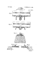
- FIG. 1 is a plan view showing my invention applied to a metal tie.
- Fig. 2 is an enlarged side elevation viewed on the line 22 of Fig. 1 and showing the fastener applied to Fig- 3 is, top plan view of'the compound form of-fastener.
- Fig. 3 is an elevation in edge view of the fastener taken on the line of Fig. 2 and looking in the direction of the arrows.
- Fig. 4 is an elevation of the fastener on the line ld of Fig.
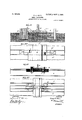
- Fig. 5 and 6 are cross sections through difierent forms of metal ties showing modifications of the invention.
- Fig. '7 is a top plan view showing another application of my invention to a metal tie.
- -Fig. 8 is a cross section through a concrete or composition tie taken on the line 8-8 of Fig. 13, and showing another form of my invention.
- Fig. 9 is a'sectional view showing another form of my invention applied to a rail supporting plate.
- Fig. 10 is a further modification showing another form of rail supporting plate.
- Fig. 11 is anenlarged cross-section showing on larger scale the rail supporting plate P, P.
- Fig. 12 is a vertical section taken on the line 1212 of Fig. 11'.
- Fig. 13 is a view taken in a plane longitudinally to the tie and transversely to the rail-and showing the application of arail-supportingplate on the top of the composite or concrete tie.
- Fig. 14 is a view taken in a plane longitu dinally to the tie and transversely to the rails showingv the application of my invention as an alinement bar for switches, etc.
- Fig. 15 is a sec tional view taken on the-line 1515 of Fig.
- Fig. 16 is a view of the concrete or composition tie taken in a plane at right-angles to the rails, showing form of my invention appliedto the same.
- Fig. 17 is a transverse section of the tie and plate taken on the line 1717 of Fig. 16. side elevation and top plan view, respectively, of another form of my invention.
- Figs. 19, 19, 19 are, respectively, longitudinal section of tie, top plan view and perspective of still another form of my invention.
- Figs. 20 and 20 are, respectively, a
- Figs. 21, 22, and 23 are transverse sections of metal ties of still other modified forms.
- Fig. 22 is a cross section of the same form of tie SllOWll in Fig. 22, but with a one-piece rail clamp A applied to the same, instead of a compound rail clamp, and Fig. 22* is a detail in perspective showing the one-piece rail clamp.
- Ll and are the two running rails and P. the cross-over or switch rail laid on' the tie, as formed of the two metal sections X and X. As shown these two metal sections are spaced apart by means of metalfilling blocks x which are riveted, bolted or otherwise fastened between the two sections of the tie, so as to leave between the'said tie sections longi. tudinal opening or slot running as desired substantially theiull length or only in portions of the length of the tie.
- the tie Within the longitudinal slot, of the tie are arranged any number of my compound rail clamps consistingeach of the two sections A and B; or where the clamp is desired, made ⁇ of only one piece, as hereinafter described and claimed, the two metal sections of the tie X and X would be holted or otherwise adjustahly fastened together. faces the slot of the tie are deformed or fashioned into clutch faces so as to securely engage the corresponding faces of the two,
- Figs. 18 and 18 are a sectional sections pf my rail clamp, or the two faces of the oneiece rail clamp. The faces of this 4 the rail under a load.
- the clutch faces on one side of the slot are in the nature of vertical and parallel corrugations, serrations, saw-tootl'n'ng or other deformations and the clutch faces on the other side of said'slot are horizontal, parallel-corrugations, serrations, saw-toothing or other deforinations.
- the other section B of my compound clamp v 9 has its external wall fashioned into horizontal corrugations, serrations, saw-toothing or other deformations meshing and interlocking with the horizontal corrugations, serrations, saw-toothing or other deformations of the other side of the tie slot.
- the section B of theclamp is provided with an overhanging lip or'lug b, which bears upon the up er'surface of the base of ithe rail and holds Ste samedown to the tie.
- Theother section A'of the clamp is provided with or see Fig. 3, which extends behindthe outer .end .of the. clamp section B.
- the two clamp sections A and'B are' formed on their adjacentfaces with interlocking means con sisting of the rib'or other deformation (1 on the section A- and the corresponding groove'or otherinterlocking deformation 1) in the section B -wbich when interlocked prevent the horizontal separation of'the two sections; or the groove or other interlocking deformation 6 may be on the section A, and
- the rib or other deformation a" may be on the section B, or vice versa as may be desired.
- the two sectionsA'a-nd B are also looked against vertical movement away from each other means of a horizontal perforation and a cotter key, rivet, bolt or w her means of fastening C. .5
- the clamp section f having the horizontal corrugations on itsouter face is adjusted to the rail base with the corrugations, serrations, saw-toothing or other deformations of the section .B interlocked with the'horizontal corrugations, serclamp sideof the slot while the interlocking rib or other deformation a" enters the vertical groove or interlocking deformation 6 of the other SECtl011.
- This clutch connection pretions A and B and when the cotter key, rivet, bolt or other means of fastening C is passed through the sections A'and B it will be seen that the section A is also locked against vertical movement, so that the compound clamp A, B is rigidly fixed-in place as against displacing strains in all directions.
- the compound A, B may be inserted at anv point along the length of saidslot to adapt it to the varying widths of the rail bases or to the position of the switch rail, or tothe variations of the gage of the running rails.
- the metal orcomposition tie in Fig, .5 maybe either of integral cit-composite construction with a longitudinal. channel way, while in Fig. 6 the metal tie may be formed in two pieces with the slot and its clutch faces formed in a subjacent T shape bar, X, or'the same may be of channel bar construction with angle bars set on its face bearing the clutch faces.
- Fig. 7 I show a-top plan view of a metal vents the horizontal separation of the sec tie with my locking and clamping devices in such position of the tie only as may be subj ect to variations due to possible adjustments in the widths of'rail bases, but the width of the gage would not be materially altered.
- the slot is not co-extensive with the length of the tie X but only extends a short distance on each side of the rails.
- a concrete or composition tie serves to sup ort a special fOIlll'Of plate on which the rai is carried and which plate is fashioned to receive my rail clamp A, B.
- Said rail plate in this case may be made of two sections P and-P fitted together with a longitudinal ,rabbet.
- said rail-plate may be of only one piece and the two adjacent faces of the slot in the same provided respectively, with vertical andhorizontal corrugations, serrations, sawtoothing or other clutch deformations which mesh and interlock with the clutch faces of the elam'p.
- Bolts or other means of fasten Can senses ing (Z pass throu h the two sections of the plate, or the one section as the case may be and anchor the same to the subjacent concrete or composite or other structure.
- FIGQ 9 substantially the same plate as shown in Fig. 8 is employed, but one of the members of my rail clamp is formed with a laterally projecting lug Z at its lower end which enters a recess in one of the plate sections P so as to firmly lock the clamp against upward movement.
- I show a rail bearing plate, or commonly called tieplate, for a rail somewhat similar to that employed in Figs. 8 and 9 and having its up per surface formed with depressions.
- Fig. 11 shows, in enlarged. cross-section taken on the line 11 11 of Fig. 13, the twopart base plate for the rail
- Fig. 12 is one form of'section taken on the line l212 of Fig. 11 showing the manner of holding down the rail base to the base plate by the overlapping of my compound clamp
- Fig. 13 shows the side view of the concrete or composition'railway tie showing the application [thereto of my invention as set forth in detail in Figs. 11 and 1'2 and showing also an elastic cushion S which may be inserted between the plate and the concrete or composition tie.
- a transverse alinement bar E is shown as employed in place of a tie to which nay-inven ion is shown applied for holding the rails in alinenient for use at switches, or at such points where use of such bar is found desirable.
- Fig. 17 may be modified in many other ditl'erent
- the clutch faces forms. forming the slot may be merely bars running longitudinally through the length or portions oi the length of the tie, and the rail made to bear directly on the tie; or the same may be made and applied shown the drawings by means of the saddles T either overlappingthe o? *"ic shown rely lap- ;nng o no lying on the top of t lie tie.
- the faces of the clamp may have the symmetrical clutch projections and the faces of the slot have the horizontal and vertical corrugations opposite each other, or vice versa as desired.
- the vertically in sertible member A is provided with vertical corrugations, serrations, saw toothing or other clutch deformations on both of its sides, the vertical corrugations on one'side extending throughout theentire face of said member which comes in contactwith'lace of the slot and the vertical corrugations on the other side shown at a being formed on that portion of the member A"wliiclfiextends behind the cooperating iii'ember B.
- the vertically insertible Inembe'rA has-an interlocking clutch connection with both olt'he clutch faces on the opposite sides of the'slot. 1
- Figs. 20 and 20 thesanie arrangement of clutch faces and clamp members is"employed as in Figs. 19 and lg' except that in the latter figures the clutch faces of the slot are formed in independent platesM bolted, riveted or otherwise fastened to the two parts of the metal tie X, while in Figs. 20 and 2O clutch faces are formed directly on the inner surfaces of the tie sections X
- Fig. 21 which shows a form of metallic tie with a subjacent plate 0 applied to the same and containing the clutch faces, the plate and the tie are fastened together by rivets, bolts or other means of fastening F, and which may if desired also secure cushions G to the metal tie. T he elastic cushions G may be used or left off entirely and the rail made to bear directly on the tie it so desired.
- a different form of metallic tie is shown composed oia T -bar I ant we angle bars, or other bars, X and'X bolted, riveted or otherwise fastenedv to the web of of the T-bar and to each other by bolt, rivet or other fastening H, the clutch faces being formed on the inner surfaces of the said bars.
- the two angle bars am- X are bolted or otherwis ljustably fastened to the web of the T-barl so as to allow the cluth faces on the inner faces or surfaces of the ar bars to be drawn up tight and locked and internu against corresponding sides oi.
- the tie islormed of two cnanne irons X and X connected by bolls, "iv'cts or the rails in positionwhere the same are sub' ject to being moved-such as switch fastenings, attaching crane rails to crane girders, attachingmembers to I-beams, rolled or other shapes.
- a permanent railroad tie or roadbed may be employed and any width of base or flange of rail may be. used and the gage maintained, or the gage itself may be changed if desired and the devices and ties be used repeatedly and for any length of time without the necessity of renewal.
- a railfastening consisting of a rail supporting member having a slot running transversely to the rail with the adjacent vertical faces of said slot wrought into clutch formations and a rail clamp with corresponding clutch formations fitting between and interlooking with both of said opposite clutch formations of the rail supporting member.
- a rail fastening consisting of a rail supporting member having a slot running transversely to the rail with the adjacent vertical faces, of said slot wrought into clutch formations, and a compound rail clamp made in two parts, each having on its exterior side clutch formations "corresponding to the clutch formations of the adjacent side of the supporting member,said compound rail clamp being provided with interlocking means and fitting between and interlocking with both of said opposite clutch formations of the rail supporting member.
- a rail fastening consisting of a rail supporting member having a slot running transversely to the rail with the adjacent vertical jfaces of said slot wrought intoclutch formae tions, and a two-part rail clamp, one part 1 being formed with clutch formations of alooking direction, and a rail clamp having on its opposite sides clutch formatlons fitting between and interlocking with the clutch formations dfJooth the rail supporting members.
- a rail fastening consisting of a rail supporting member having a slot running transversely to the rail with the adjacent vertical faces of said slot wrought into clutch formations, said rail supporting member being also divided intotwo parts with one overlappin the other with a rabbeted joint, and a rai clamp with clutch formations fitting between and interlocking with both of said opposite clutchformat-ions of the rail supporting member.
- a rail fastening consisting of a rail sup porting member having a slot running transversely to the rail with the adjacent vertical faces of said slot wrought into clutch formations, said rail supporting member being also divided into two parts with one overlapping the other with a rabbeted joint, and a rail clamp with clutch formations fitting between and interlocking with both of said opposite clutch formations of the rail supporting member, and a composite base arranged beneath the rail supporting member.
- a rail'fastemng comprising a rail su port having an opening running transverse y to the rail with clutch formations on both the opposite faces of the said opening, and a compound rail-clamp composed of two members, one of the same having an external clutch'face slidable in one direction into the clutch faces of one side of the opening and locking in the other direction, and the other member having clutch faces slfidable into the clutch faces of the-other side of the opening by a movement at right angles to the sliding movement of the other member, one of said members having anoverhanging lug for' overlapping the rail. base.
- a rail fastening comprising a rail su port having an opening running transverse y to the rail with clutch formations 011 both the oppositefaces of the said opening, and a compound rail clamp composed of two mem bers, one of the same having an external clutch face slidable in one direction into theclutch faces of one side of the opening and locking in t-he'other direction, and the other 30 senses member having clutch faces slidable into the clutch faces of the other side of the opening by a movement at right angles to the sliding movement of the othenmember, one of the said members having an overhanging lug for overlapping the rail base, and means for locking the two members of the compound clamp against separation from each other.
- a rail fastening comprising a rail support having an opening running transversely to the rail with clutch formations on both the opposite sides or faces of the said opening, and a compound rail clamp composed of two members, one of the same having an external clutch face slidable in one direction into the clutch faces of one side of the opening and locking in the other direction, and the other member having clutch faces slidable into the clutch faces'of the other side of the opening by a movement at right angles to the sliding movement of the other member, one of the said members having an overhanging lug for overlapping the rail base, means for locking the two members of the compound clamp against separation from each other in horizontal direction, and IDQELHS'fOI looking them tion in vertical direction.
- a rail f "ening comprising a tivmpart rail clamp, ibined with rail support slotted transversely to the rail and having clutch faces 1 both the innersides of the slot, the ti. 's of We rail clamp having clutch faces l l with both clutch faces of i longitudina iustable th t j to the rail,
- a rail fastening comprising a two-part rail clamp, combined with a rail support slotted transversely to the rail and having clutch faces on both the inner sides of the slot,the two parts of the rail clamp having faces of the slot and longitudinally and verti cally adjustable the-rein transversely to the rail, the rail support being formed in two separable parts fastened together, and a railroad tie arranged beneath the two part rail support, and'a fastening for securing the two parts of the rail support to each other and also to the subjacent tie or roadbed.
- rail fastening comprising a two-part rail clamp, combined with a rail support slotted transversely to the rail and having clutch faces on both the inner faces of the slot, the two parts of the rail clamp having clutch faces interlocking with the clutch of the slot and longitudinally and vertically adjustable therein transversely to the rail, the clutch faces of the two members of the two-part clamp having a slidable conformation right angles to each other and the clutch faces on both sides of the opening in the rail support being exactly alike.
- a rail fastening comprising a two-part ail clamp combined with a rail support otted transversely to the rail andhaving ilar clutch faces on both sides of the s slot, each with interlocking grooves atright angles, one of the rail clamp members having vertical clutch formations on both of. its parallel sides interlocking the clutch formations on both sides of the slot, and
- a rail fastening comprising a r port having an opening running trans tot-he rail With clutch formations o the opposite faces of said opening, one clutch formations bein horizontal and clutch faces interlocking with the clutch other vertical, and a rai clamp, one side face 14.
- a rail fastening comprising a rail su ofthe same bearing against and intermeshing and interlocking with the face of the slot opening having clutch formations running in ace a horizontal direction, and the other side of the said clamp bearing against and interlocking and intermeshing with; the other face running in a vertical of the slot opening, havin clutch formations direction, said rail clamphaving an overhanging lug overlapping the base of the rail, and means for ad- ]usting and locking the faces of the said slot openin against the faces of the said clamp.
- said slot being formed by two separate railsupporting sections connected together, and,
- the rail clamp having clutch faces interlocking and intermeshing nith the clutch faces of the slot and longitudinally and vertically adjustable therein transversely to the rail.
- a rail fastening comprising a rail clamp, combined with a rail supp rt slotted transversely to the rail, and hav ng clutch faces on both the inner faces of the said slot,
- the rail clamp having clutch faces interlockmg and interineshing with the clutch faces of the slot and-longitudinally and vertically 7 adjustable therein transversely to the rail, the rail support being formed in two arts separable from each other and bolte to gether.
- a rail fastening comprising a rail support having an opening running transversely senses to the rail with horizontal clutch formations on one side of the opening, and vertical clutch formations on the other side of the opening, and a rail clamp, one'side face of the said rail clamp having vertical lutch forum-- tions, and the other side of i118- fa'ce of said clamp having horizontal clutch format-ions, each matching anc interlocking with and internieshing with their respective sides of the clutch faces of the slot opening next to the-same.
- 1h rail fastening com rising a rail clamp having opposite clutc faces, combined with a rail support slotted transversely to the rail-and having clutch faces on both the inner faces. of the slot, the two side faces of the said rail clamp having clutch faces interlocking with the clutch faces of the slot and longitudinally and vertically adjustable therein transversely to the rail, the rail sup port being formed in two separable parts fastened together, and a railroad tie arranged beneath the two-part rail support, and means for securing the two-parts of the rail support to each other and also to the subjacent tie or roadbed.
- a rail fastening comprising a rail clamp, having opposite clutch faces combined with a rail support slotted transversely to the rail and having clutch faces on bot-l1 the inner faces of the slot, the rail clanip having its clutch faces interlocking and internieshing with the clutch faces of the slot and longitudinally and vertically adjustable therein transversely to the rail, and the clntchfaces of the two-sides respectively of the rail clamp having inserting conformations at right angles to each other, and the clutch faces on both sides ofthe slot opening in the rail support being exactlyalike.
Landscapes
- Life Sciences & Earth Sciences (AREA)
- Pest Control & Pesticides (AREA)
- Health & Medical Sciences (AREA)
- General Health & Medical Sciences (AREA)
- Toxicology (AREA)
- Engineering & Computer Science (AREA)
- Insects & Arthropods (AREA)
- Wood Science & Technology (AREA)
- Zoology (AREA)
- Environmental Sciences (AREA)
- Clamps And Clips (AREA)
Description
'PATENTED EPT. 1, 1903.
0. A. HALL. RAIL FASTENER.
APPLICATION IILBD NOV. 14, 1907.
a sums-11mm 1.
m M w u N B. H "n. R
V: W B u a? l H. 5
WITNESSES A TTORNEYS INVENTOI? OLIVER f1 HALL PATENTED SEPT. 1, 1908.
s SHEETS-SHEET 2.
O. A. HALL.
' I RAIL FASTENER.
APPLICATION 11,111) NOV 14, 1907 WITNESSES A TTOHNEYS 8 0 l L m P E S D E T N E T. A .LLfi-NU E mm A A? an A APPLIOATION rum: 1m}. 14, 1907.
s sums-sum a.
INVENTOI? OLIVER f1 H ALL er ATTORNEYS No. 897,828.. PATENTED SEPT. 1, 1908. o. A. HALL.
RAIL PASTENER. APPLICATION FILED NOV. 14, 1907.
8 SHEETS-SHEET 4.
INVENTOH OLIVER flJinLL;
wlrussss's No. 897,828. PATENTED SEPT. 1, 1908; 0. A. HALL.
RAIL PASTENER.
APPLICATION FILED NOV. 14, 1907.
8 SHEETS-SHEET 5.
H S V! M U n A H "HY RB CL N L U WITNESSES PATENTED SEPT. 1,1908.
7 0. A. HALL. RAIL 'FASTENBE. APPLICATION FILED NOV. 14, 1907.
8 SHEETS-SHEET 6.
I I I I I I I I I I I I I I I I. I I I I I I I I I I I I I I n I lI(IIIIllIIIIIIIIIIIIIIIIIIIIII/ INVENTOR UuvcR fi. HALL,
WITNESSES v msszsza. 0 A HALL PATENTED SEPT. 1, 190a.
BAIL FASTENER. APPLICATION FILED NOV 14, 1907 8 SHBETFBHEET 7- INVENTOI? VER h. HALL mHmlllu idnllnmi5 WITNESSES 54 Ufa/Mu AZTOHNEYS No. 897,828. PATENTED SEPT. 1, 190s.
- 0. A. HALL RAIL FASTENER. APPLICATION FILED 17017.14, 1907.
8 SHEETS-SHEET 8.
INVENTOH OLIVER R. HALL;
I WITNESSES A 7TOHNEYS in w $1 251 OLIVER A. HALL, OF OMAHA, NEBRASKA.
nain-ras'rnnnn.
Specification of Letters ratent.
Patented Sep 1, 1908.
Application filedll'ovember 14,1901; Seria1No.. .02,1.73i
To all whom it may concern:
Be it known that I, OLrvnn- A. HALL, a citizen of the United States, and a resident of Omaha, in the county of Douglas and State of Nebraska, have invented certain and locking a railroad rail in alinement with or to a tie or. road-bed without the necessity the rail.
of injuring or defacing the tie or ro'adbed and to provide for adjustment for different widths I of rail bases and widths of gage without defacing or injuring the tie or roadbed or thenecessity or, providing new ties or bars whenever the rail sizes or widthsof track gages are changed; also to allow the use of any form of tie or roadhed desired, such as concrete, composition, metal, wood, etc., which can be set permanently in place and therails renewe d or changed as tosizes as often or when ever desired. I
To hese ends my invention consists in either the compound or one piece form of fastener as hereinafter claimed, and in the combination of the same .with'a special form of rail support, as hereinafter more fully described with reference to the drawings, in which 1 Figure 1 is a plan view showing my invention applied to a metal tie. Fig. 2 is an enlarged side elevation viewed on the line 22 of Fig. 1 and showing the fastener applied to Fig- 3 is, top plan view of'the compound form of-fastener. Fig. 3 is an elevation in edge view of the fastener taken on the line of Fig. 2 and looking in the direction of the arrows. Fig. 4 is an elevation of the fastener on the line ld of Fig. 1 and looking in the opposite direction to Fig. 2. Figs. 5 and 6 are cross sections through difierent forms of metal ties showing modifications of the invention. Fig. '7 is a top plan view showing another application of my invention to a metal tie. -Fig. 8 is a cross section through a concrete or composition tie taken on the line 8-8 of Fig. 13, and showing another form of my invention. Fig. 9 is a'sectional view showing another form of my invention applied to a rail supporting plate. Fig. 10 is a further modification showing another form of rail supporting plate. Fig. 11 is anenlarged cross-section showing on larger scale the rail supporting plate P, P. Fig. 12is a vertical section taken on the line 1212 of Fig. 11'. Fig. 13 is a view taken in a plane longitudinally to the tie and transversely to the rail-and showing the application of arail-supportingplate on the top of the composite or concrete tie.
Fig. 14 is a view taken in a plane longitu dinally to the tie and transversely to the rails showingv the application of my invention as an alinement bar for switches, etc. Fig. 15 is a sec tional view taken on the-line 1515 of Fig.
14, and slightly enlarged. Fig. 16 is a view of the concrete or composition tie taken in a plane at right-angles to the rails, showing form of my invention appliedto the same. Fig. 17 is a transverse section of the tie and plate taken on the line 1717 of Fig. 16. side elevation and top plan view, respectively, of another form of my invention. Figs. 19, 19, 19 are, respectively, longitudinal section of tie, top plan view and perspective of still another form of my invention. Figs. 20 and 20 are, respectively, a
longitudinal section of tie, and planof an other form. Figs. 21, 22, and 23 are transverse sections of metal ties of still other modified forms. Fig. 22 is a cross section of the same form of tie SllOWll in Fig. 22, but with a one-piece rail clamp A applied to the same, instead of a compound rail clamp, and Fig. 22* is a detail in perspective showing the one-piece rail clamp.
Referring to Fig. 1., Ll and are the two running rails and P. the cross-over or switch rail laid on' the tie, as formed of the two metal sections X and X. As shown these two metal sections are spaced apart by means of metalfilling blocks x which are riveted, bolted or otherwise fastened between the two sections of the tie, so as to leave between the'said tie sections longi. tudinal opening or slot running as desired substantially theiull length or only in portions of the length of the tie. Within the longitudinal slot, of the tie are arranged any number of my compound rail clamps consistingeach of the two sections A and B; or where the clamp is desired, made {of only one piece, as hereinafter described and claimed, the two metal sections of the tie X and X would be holted or otherwise adjustahly fastened together. faces the slot of the tie are deformed or fashioned into clutch faces so as to securely engage the corresponding faces of the two,
The inner vertical.
Figs. 18 and 18 are a sectional sections pf my rail clamp, or the two faces of the oneiece rail clamp. The faces of this 4 the rail under a load. As shown, the clutch faces on one side of the slot are in the nature of vertical and parallel corrugations, serrations, saw-tootl'n'ng or other deformations and the clutch faces on the other side of said'slot are horizontal, parallel-corrugations, serrations, saw-toothing or other deforinations.
Theisection A' of my com ound clamp is formed'on its externalv wal Figs. 1 to 4,-
" without, as desired, a rectangular flange a,
with vertical corrugations, serrations, sawtootlnng or other deformations meshing or interlocking with the verticalcorrugations,
serrations,.saw-toothing or otherdeforma-' tions-of the tie on one side-of the slot, and the other section B of my compound clamp v 9 has its external wall fashioned into horizontal corrugations, serrations, saw-toothing or other deformations meshing and interlocking with the horizontal corrugations, serrations, saw-toothing or other deformations of the other side of the tie slot. The section B of theclamp is provided with an overhanging lip or'lug b, which bears upon the up er'surface of the base of ithe rail and holds Ste samedown to the tie. Theother section A'of the clamp is provided with or see Fig. 3, which extends behindthe outer .end .of the. clamp section B. The two clamp sections A and'B are' formed on their adjacentfaces with interlocking means con sisting of the rib'or other deformation (1 on the section A- and the corresponding groove'or otherinterlocking deformation 1) in the section B -wbich when interlocked prevent the horizontal separation of'the two sections; or the groove or other interlocking deformation 6 may be on the section A, and
therib or other deformation a" may be on the section B, or vice versa as may be desired. The two sectionsA'a-nd B are also looked against vertical movement away from each other means of a horizontal perforation and a cotter key, rivet, bolt or w her means of fastening C. .5
As will be seen in-Fig. 1, the clamp section f; having the horizontal corrugations on itsouter face is adjusted to the rail base with the corrugations, serrations, saw-toothing or other deformations of the section .B interlocked with the'horizontal corrugations, serclamp sideof the slot while the interlocking rib or other deformation a" enters the vertical groove or interlocking deformation 6 of the other SECtl011." This clutch connection pretions A and B and when the cotter key, rivet, bolt or other means of fastening C is passed through the sections A'and B it will be seen that the section A is also locked against vertical movement, so that the compound clamp A, B is rigidly fixed-in place as against displacing strains in all directions. It.w ill also be seen that as the-corrugations, serrations, saw-toothing or other clutch deforma tions in the sides of the, slot are. (o-extensive with the length of the tie slot, the compound A, B may be inserted at anv point along the length of saidslot to adapt it to the varying widths of the rail bases or to the position of the switch rail, or tothe variations of the gage of the running rails.
In Figs. 5 and 6, I have shown how my invention is applicableto two difierent forms of metal or composition ties, the metal orcomposition tie in Fig, .5 maybe either of integral cit-composite construction with a longitudinal. channel way, while in Fig. 6 the metal tie may be formed in two pieces with the slot and its clutch faces formed in a subjacent T shape bar, X, or'the same may be of channel bar construction with angle bars set on its face bearing the clutch faces.
In Fig. 7, I show a-top plan view of a metal vents the horizontal separation of the sec tie with my locking and clamping devices in such position of the tie only as may be subj ect to variations due to possible adjustments in the widths of'rail bases, but the width of the gage would not be materially altered. In such case the slot is not co-extensive with the length of the tie X but only extends a short distance on each side of the rails.
In Fig. 8 I have shown a form of my invention in which a concrete or composition tie serves to sup ort a special fOIlll'Of plate on which the rai is carried and which plate is fashioned to receive my rail clamp A, B. Said rail plate in this case may be made of two sections P and-P fitted together with a longitudinal ,rabbet. joint as shown, or said rail-plate may be of only one piece and the two adjacent faces of the slot in the same provided respectively, with vertical andhorizontal corrugations, serrations, sawtoothing or other clutch deformations which mesh and interlock with the clutch faces of the elam'p.' Bolts or other means of fasten Can senses ing (Z pass throu h the two sections of the plate, or the one section as the case may be and anchor the same to the subjacent concrete or composite or other structure.
InFigQ 9 substantially the same plate as shown in Fig. 8 is employed, but one of the members of my rail clamp is formed with a laterally projecting lug Z at its lower end which enters a recess in one of the plate sections P so as to firmly lock the clamp against upward movement. in Fig. 10, I show a rail bearing plate, or commonly called tieplate, for a rail somewhat similar to that employed in Figs. 8 and 9 and having its up per surface formed with depressions.
.Fig. 11 shows, in enlarged. cross-section taken on the line 11 11 of Fig. 13, the twopart base plate for the rail, and Fig. 12 is one form of'section taken on the line l212 of Fig. 11 showing the manner of holding down the rail base to the base plate by the overlapping of my compound clamp; Fig. 13 shows the side view of the concrete or composition'railway tie showing the application [thereto of my invention as set forth in detail in Figs. 11 and 1'2 and showing also an elastic cushion S which may be inserted between the plate and the concrete or composition tie.
In ll and 15 a transverse alinement bar E is shown as employed in place of a tie to which nay-inven ion is shown applied for holding the rails in alinenient for use at switches, or at such points where use of such bar is found desirable. I
In hi 1%- and arehriorced concrete or composition tie is provided with my invention to the same by means of the sadles T. Fig. 17 may be modified in many other ditl'erent The clutch faces forms. forming the slot may be merely bars running longitudinally through the length or portions oi the length of the tie, and the rail made to bear directly on the tie; or the same may be made and applied shown the drawings by means of the saddles T either overlappingthe o? *"ic shown rely lap- ;nng o no lying on the top of t lie tie. v
In l 18 and I the two rnenibers A and E o i ed 1'11 a ma: scribed b are OllS'tlUCt- .siinilar that air iv dec or opposite i'csupport 1: are to say, instead or stilt slot with vertical 7 ns on the one side and horizontal saw too thing or other clutch deformations on the other side sic the corrugations on both sides of the slot are both vertical and horizontal, re solving the adjacent or opposite faces of the slot into'a surface of symmetrical clutch projectionswhich;engage alike with the vertical cor ngatio'ns offthe section A and the hori- Zont'al corrugations of the section B. Or the faces of the clamp may have the symmetrical clutch projections and the faces of the slot have the horizontal and vertical corrugations opposite each other, or vice versa as desired. in Figs. 19, 19, and lat) the vertically in sertible member A is provided with vertical corrugations, serrations, saw toothing or other clutch deformations on both of its sides, the vertical corrugations on one'side extending throughout theentire face of said member which comes in contactwith'lace of the slot and the vertical corrugations on the other side shown at a being formed on that portion of the member A"wliiclfiextends behind the cooperating iii'ember B. In this form of the device it willbe' seen that the vertically insertible Inembe'rA has-an interlocking clutch connection with both olt'he clutch faces on the opposite sides of the'slot. 1
In Figs. 20 and 20 thesanie arrangement of clutch faces and clamp members is"employed as in Figs. 19 and lg' except that in the latter figures the clutch faces of the slot are formed in independent platesM bolted, riveted or otherwise fastened to the two parts of the metal tie X, while in Figs. 20 and 2O clutch faces are formed directly on the inner surfaces of the tie sections X In Fig. 21 which shows a form of metallic tie with a subjacent plate 0 applied to the same and containing the clutch faces, the plate and the tie are fastened together by rivets, bolts or other means of fastening F, and which may if desired also secure cushions G to the metal tie. T he elastic cushions G may be used or left off entirely and the rail made to bear directly on the tie it so desired.
In Fig. a different form of metallic tie is shown composed oia T -bar I ant we angle bars, or other bars, X and'X bolted, riveted or otherwise fastenedv to the web of of the T-bar and to each other by bolt, rivet or other fastening H, the clutch faces being formed on the inner surfaces of the said bars.
in the one-piece form of my rail clamp, shown at A in Fig. 22 and 22", the two angle bars am- X are bolted or otherwis ljustably fastened to the web of the T-barl so as to allow the cluth faces on the inner faces or surfaces of the ar bars to be drawn up tight and locked and internu against corresponding sides oi.
but piece rail clamp, and therai ed to the rail base by loo or other means of adjus in Fig. the tie islormed of two cnanne irons X and X connected by bolls, "iv'cts or the rails in positionwhere the same are sub' ject to being moved-such as switch fastenings, attaching crane rails to crane girders, attachingmembers to I-beams, rolled or other shapes.
In making use of my invention I wish to have it. further understood that whereas the drawings show clutch deformations running longitudmally and. vertically only, I do not confine this application to clutch deforma tions running in these directions alone, but said clutch deformations maybe made to run in any direction found desirable or at any angle.
' In making use of my invention, I wish to have it further understood that whereas these drawings accompanying these specifihave been applied to the securing of railroad rails to their subj acent bed, and do not claim this broadly.
By means of my invention a permanent railroad tie or roadbed. may be employed and any width of base or flange of rail may be. used and the gage maintained, or the gage itself may be changed if desired and the devices and ties be used repeatedly and for any length of time without the necessity of renewal.
' I claim:
1. A railfastening, consisting of a rail supporting member having a slot running transversely to the rail with the adjacent vertical faces of said slot wrought into clutch formations and a rail clamp with corresponding clutch formations fitting between and interlooking with both of said opposite clutch formations of the rail supporting member.
2. A rail fastening, consisting of a rail supporting member having a slot running transversely to the rail with the adjacent vertical faces, of said slot wrought into clutch formations, and a compound rail clamp made in two parts, each having on its exterior side clutch formations "corresponding to the clutch formations of the adjacent side of the supporting member,said compound rail clamp being provided with interlocking means and fitting between and interlocking with both of said opposite clutch formations of the rail supporting member.
3. A rail fastening, consisting of a rail supporting member having a slot running transversely to the rail with the adjacent vertical jfaces of said slot wrought intoclutch formae tions, and a two-part rail clamp, one part 1 being formed with clutch formations of alooking direction, and a rail clamp having on its opposite sides clutch formatlons fitting between and interlocking with the clutch formations dfJooth the rail supporting members.
5. A rail fastening, consisting of a rail supporting member having a slot running transversely to the rail with the adjacent vertical faces of said slot wrought into clutch formations, said rail supporting member being also divided intotwo parts with one overlappin the other with a rabbeted joint, and a rai clamp with clutch formations fitting between and interlocking with both of said opposite clutchformat-ions of the rail supporting member.
6. A rail fastening, consisting of a rail sup porting member having a slot running transversely to the rail with the adjacent vertical faces of said slot wrought into clutch formations, said rail supporting member being also divided into two parts with one overlapping the other with a rabbeted joint, and a rail clamp with clutch formations fitting between and interlocking with both of said opposite clutch formations of the rail supporting member, and a composite base arranged beneath the rail supporting member.
7. A rail'fastemng, comprising a rail su port having an opening running transverse y to the rail with clutch formations on both the opposite faces of the said opening, and a compound rail-clamp composed of two members, one of the same having an external clutch'face slidable in one direction into the clutch faces of one side of the opening and locking in the other direction, and the other member having clutch faces slfidable into the clutch faces of the-other side of the opening by a movement at right angles to the sliding movement of the other member, one of said members having anoverhanging lug for' overlapping the rail. base. 8. A rail fastening, comprising a rail su port having an opening running transverse y to the rail with clutch formations 011 both the oppositefaces of the said opening, and a compound rail clamp composed of two mem bers, one of the same having an external clutch face slidable in one direction into theclutch faces of one side of the opening and locking in t-he'other direction, and the other 30 senses member having clutch faces slidable into the clutch faces of the other side of the opening by a movement at right angles to the sliding movement of the othenmember, one of the said members having an overhanging lug for overlapping the rail base, and means for locking the two members of the compound clamp against separation from each other.
9. A rail fastening, comprising a rail support having an opening running transversely to the rail with clutch formations on both the opposite sides or faces of the said opening, and a compound rail clamp composed of two members, one of the same having an external clutch face slidable in one direction into the clutch faces of one side of the opening and locking in the other direction, and the other member having clutch faces slidable into the clutch faces'of the other side of the opening by a movement at right angles to the sliding movement of the other member, one of the said members having an overhanging lug for overlapping the rail base, means for locking the two members of the compound clamp against separation from each other in horizontal direction, and IDQELHS'fOI looking them tion in vertical direction.
10. A rail f "ening comprising a tivmpart rail clamp, ibined with rail support slotted transversely to the rail and having clutch faces 1 both the innersides of the slot, the ti. 's of We rail clamp having clutch faces l l with both clutch faces of i longitudina iustable th t j to the rail,
11. it ran r comprising a tJO-i rail clamp, ibined with a rail supuop slotted transversely to the rail and haviru clutch faces or both the inner sides of ti e slot, the two 1 of the rail clamp ha clutch far ii "nngrvith both the faces of the SiOL- and vertically ad;. r- 1 therein transversely t against separa to the rail an the inner sides f the rail clamp h: i with both the cl 'itudinally and v ransversely ti. c :ing fprmed in clutch faces an both the inner sides of the vslot, the two par of the rail clamp having .clutch faces lnterlockmg with both the clutch faces of the slot and longitudinally adjustable therein transversely to the rail, the rail support being formed into separable parts fastened together, and one of the clamp sections being formed with an underlapping lug housed Within the joint of the two-part rail support.
'port having an opening running transverse y to the rail with horizontal clutch formations on one side of the opening and vertical clutch formations on the other side o the opening, and a compound rail clamp composed of tyre interlocking members, one having vertical clutch formations on its outer side and the. other having horizontal clutch formations on the out-er side.
15. A rail fastening comprising a two-part rail clamp, combined with a rail support slotted transversely to the rail and having clutch faces on both the inner sides of the slot,the two parts of the rail clamp having faces of the slot and longitudinally and verti cally adjustable the-rein transversely to the rail, the rail support being formed in two separable parts fastened together, and a railroad tie arranged beneath the two part rail support, and'a fastening for securing the two parts of the rail support to each other and also to the subjacent tie or roadbed.
3%. it. rail fastening comprising a two-part rail clamp, combined with a rail support slotted transversely to the rail and having clutch faces on both the inner faces of the slot, the two parts of the rail clamp having clutch faces interlocking with the clutch of the slot and longitudinally and vertically adjustable therein transversely to the rail, the clutch faces of the two members of the two-part clamp having a slidable conformation right angles to each other and the clutch faces on both sides of the opening in the rail support being exactly alike.
'27. A rail fastening comprising a two-part ail clamp combined with a rail support otted transversely to the rail andhaving ilar clutch faces on both sides of the s slot, each with interlocking grooves atright angles, one of the rail clamp members having vertical clutch formations on both of. its parallel sides interlocking the clutch formations on both sides of the slot, and
rail clamp member having-hon ns-on one side interlc slot only, and means for locking the clamp members together.
18. A rail fastening comprising a r port having an opening running trans tot-he rail With clutch formations o the opposite faces of said opening, one clutch formations bein horizontal and clutch faces interlocking with the clutch other vertical, and a rai clamp, one side face 14. A rail fastening, comprising a rail su ofthe same bearing against and intermeshing and interlocking with the face of the slot opening having clutch formations running in ace a horizontal direction, and the other side of the said clamp bearing against and interlocking and intermeshing with; the other face running in a vertical of the slot opening, havin clutch formations direction, said rail clamphaving an overhanging lug overlapping the base of the rail, and means for ad- ]usting and locking the faces of the said slot openin against the faces of the said clamp.
20. rail fastening comprising a clamp,
with opposite clutch faces, combined with a rail support slotted transversely to the rail,
said slot being formed by two separate railsupporting sections connected together, and,
. having clutch faces on both the inner faces of said slot, the rail clamp having clutch faces interlocking and intermeshing nith the clutch faces of the slot and longitudinally and vertically adjustable therein transversely to the rail.
- 21. A rail fastening comprising a rail clamp, combined with a rail supp rt slotted transversely to the rail, and hav ng clutch faces on both the inner faces of the said slot,
, the rail clamp having clutch faces interlockmg and interineshing with the clutch faces of the slot and-longitudinally and vertically 7 adjustable therein transversely to the rail, the rail support being formed in two arts separable from each other and bolte to gether.
- 22. A rail fastening, comprising a rail support having an opening running transversely senses to the rail with horizontal clutch formations on one side of the opening, and vertical clutch formations on the other side of the opening, and a rail clamp, one'side face of the said rail clamp having vertical lutch forum-- tions, and the other side of i118- fa'ce of said clamp having horizontal clutch format-ions, each matching anc interlocking with and internieshing with their respective sides of the clutch faces of the slot opening next to the-same.
23. 1h rail fastening com )rising a rail clamp having opposite clutc faces, combined with a rail support slotted transversely to the rail-and having clutch faces on both the inner faces. of the slot, the two side faces of the said rail clamp having clutch faces interlocking with the clutch faces of the slot and longitudinally and vertically adjustable therein transversely to the rail, the rail sup port being formed in two separable parts fastened together, and a railroad tie arranged beneath the two-part rail support, and means for securing the two-parts of the rail support to each other and also to the subjacent tie or roadbed.
2 1-. A rail fastening comprising a rail clamp, having opposite clutch faces combined with a rail support slotted transversely to the rail and having clutch faces on bot-l1 the inner faces of the slot, the rail clanip having its clutch faces interlocking and internieshing with the clutch faces of the slot and longitudinally and vertically adjustable therein transversely to the rail, and the clntchfaces of the two-sides respectively of the rail clamp having inserting conformations at right angles to each other, and the clutch faces on both sides ofthe slot opening in the rail support being exactlyalike.
Subscribed and sworn to this fifth day of November, A. 1)., 1907'.
OLIVER A. HALL.
Ni tnesses V EMILE W. HICKOK, WILLIAM ARTHUR.
Priority Applications (1)
| Application Number | Priority Date | Filing Date | Title |
|---|---|---|---|
| US40217307A US897828A (en) | 1907-11-14 | 1907-11-14 | Rail-fastener. |
Applications Claiming Priority (1)
| Application Number | Priority Date | Filing Date | Title |
|---|---|---|---|
| US40217307A US897828A (en) | 1907-11-14 | 1907-11-14 | Rail-fastener. |
Publications (1)
| Publication Number | Publication Date |
|---|---|
| US897828A true US897828A (en) | 1908-09-01 |
Family
ID=2966254
Family Applications (1)
| Application Number | Title | Priority Date | Filing Date |
|---|---|---|---|
| US40217307A Expired - Lifetime US897828A (en) | 1907-11-14 | 1907-11-14 | Rail-fastener. |
Country Status (1)
| Country | Link |
|---|---|
| US (1) | US897828A (en) |
-
1907
- 1907-11-14 US US40217307A patent/US897828A/en not_active Expired - Lifetime
Similar Documents
| Publication | Publication Date | Title |
|---|---|---|
| US897828A (en) | Rail-fastener. | |
| US1074942A (en) | Railway-tie and rail-fastener. | |
| US1229926A (en) | Railway-rail fastener. | |
| US928791A (en) | Railway-tie and rail-fastener. | |
| US873707A (en) | Tie-plate. | |
| US806453A (en) | Metallic railway-tie. | |
| US1049985A (en) | Metallic railroad-tie. | |
| US806340A (en) | Metallic railway-tie. | |
| US795185A (en) | Railway-tie. | |
| US985688A (en) | Rail joint and fastener. | |
| US730787A (en) | Railway-tie. | |
| US990615A (en) | Railway-rail tie and fastener. | |
| US1093129A (en) | Railway-tie. | |
| US1220948A (en) | Rail-tie plate and rail-fastener. | |
| US827881A (en) | Railway-tie. | |
| US749817A (en) | Metallic railway-tie and rail-fastener | |
| US510047A (en) | Railway-tie plate | |
| US462900A (en) | Metallic railway-tie | |
| US1126573A (en) | Railroad-tie. | |
| US1015657A (en) | Tie and rail-fastener. | |
| US1492325A (en) | Road rail for concrete pavements and analogous uses | |
| US919741A (en) | Combined guard-rail clamp and tie-plate. | |
| US1078297A (en) | Combination sole-plate and railroad-tie. | |
| US464054A (en) | Jacob c | |
| US1170351A (en) | Base-plate. |