US8934138B2 - Color processing apparatus and method, and non-transitory computer readable medium - Google Patents
Color processing apparatus and method, and non-transitory computer readable medium Download PDFInfo
- Publication number
- US8934138B2 US8934138B2 US13/663,863 US201213663863A US8934138B2 US 8934138 B2 US8934138 B2 US 8934138B2 US 201213663863 A US201213663863 A US 201213663863A US 8934138 B2 US8934138 B2 US 8934138B2
- Authority
- US
- United States
- Prior art keywords
- color
- lightness
- lowest
- chroma
- gamut
- Prior art date
- Legal status (The legal status is an assumption and is not a legal conclusion. Google has not performed a legal analysis and makes no representation as to the accuracy of the status listed.)
- Expired - Fee Related, expires
Links
Images


Classifications
-
- H—ELECTRICITY
- H04—ELECTRIC COMMUNICATION TECHNIQUE
- H04N—PICTORIAL COMMUNICATION, e.g. TELEVISION
- H04N1/00—Scanning, transmission or reproduction of documents or the like, e.g. facsimile transmission; Details thereof
- H04N1/46—Colour picture communication systems
- H04N1/56—Processing of colour picture signals
- H04N1/60—Colour correction or control
- H04N1/6058—Reduction of colour to a range of reproducible colours, e.g. to ink- reproducible colour gamut
- H04N1/6061—Reduction of colour to a range of reproducible colours, e.g. to ink- reproducible colour gamut involving the consideration or construction of a gamut surface
-
- H—ELECTRICITY
- H04—ELECTRIC COMMUNICATION TECHNIQUE
- H04N—PICTORIAL COMMUNICATION, e.g. TELEVISION
- H04N1/00—Scanning, transmission or reproduction of documents or the like, e.g. facsimile transmission; Details thereof
- H04N1/46—Colour picture communication systems
- H04N1/56—Processing of colour picture signals
- H04N1/60—Colour correction or control
-
- G—PHYSICS
- G06—COMPUTING OR CALCULATING; COUNTING
- G06K—GRAPHICAL DATA READING; PRESENTATION OF DATA; RECORD CARRIERS; HANDLING RECORD CARRIERS
- G06K15/00—Arrangements for producing a permanent visual presentation of the output data, e.g. computer output printers
- G06K15/02—Arrangements for producing a permanent visual presentation of the output data, e.g. computer output printers using printers
Definitions
- the present invention relates to a color processing apparatus and method, and to a non-transitory computer readable medium.
- a color processing apparatus including a correction unit.
- a correction unit corrects the low-lightness color to a higher lightness side higher than that of the lowest-lightness color on the achromatic color axis.
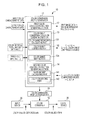
- FIG. 1 is a functional block diagram of a color processing apparatus
- FIGS. 2A to 2E are image diagrams for describing color gamut conversion processing
- FIG. 3 is a flowchart illustrating a color gamut conversion condition generating process
- FIG. 4 is a diagram for describing color gamut correction
- FIG. 5 is a diagram for describing color gamut correction
- FIG. 6 is a diagram illustrating the relationship between a color material total amount limit value and the lowest lightness
- FIG. 7 is a diagram for describing color gamut correction
- FIG. 8 is an image diagram for describing color gamut conversion processing
- FIG. 9 is a diagram illustrating the corresponding relationship between the weight of a chroma component and the color material total amount
- FIG. 10A is a diagram illustrating the corresponding relationship between the lightness of mapping anchor and the color material total amount
- FIG. 10B is a diagram for describing a change in an anchor point
- FIG. 11 is a diagram for describing color gamut mapping
- FIG. 12 is a diagram for describing the color material total amount of primary colors and secondary colors
- FIG. 13 is a diagram illustrating the corresponding relationship between a mapping angle and the color material total amount.
- FIG. 14 is a block diagram of a color processing apparatus configured using a computer.
- FIG. 1 is a block diagram illustrating the functional configuration of a color processing apparatus 10 according to an exemplary embodiment.
- the color processing apparatus 10 includes a color converter 16 , a color conversion profile storage unit 15 , and a color conversion profile generator 11 .
- the color converter 16 is provided between an input device 20 and an output device 30 .
- the color converter 16 performs color conversion processing of image data input from the input device 20 .
- the color conversion profile storage unit 15 stores a reference table (color conversion profile) to which the color converter 16 refers upon color conversion of image data.
- the color conversion profile generator 11 generates a color conversion profile stored in the color conversion profile storage unit 15 .
- the color processing apparatus 10 is realized by being included in an image forming apparatus (color copy machine), which is the output device 30 , and which forms, for example, a color image with an electrophotographic system using cyan, magenta, yellow, and key (black) (CMYK) color toners and transfers and fixes the color image on a sheet.
- image forming apparatus color copy machine
- CMYK key (black)
- the input device 20 may be, for example, an information processing terminal (client) realized using a personal computer (PC) or the like, or an image forming apparatus (color copy machine) that has a color gamut different from that of the output device 30 .
- client information processing terminal
- PC personal computer
- image forming apparatus color copy machine
- image data in the red, green, and blue (RGB) color space which is generated by a user who checks the colors on a display of the client, is input as a target of color gamut conversion to the color converter 16 .
- the image forming apparatus inputs image data in the CMYK color space as a target of color gamut conversion to the color converter 16 .
- the color conversion profile generator 11 includes a first color conversion condition generating section 12 , a color gamut conversion condition generating section 13 , and a second color conversion condition generating section 14 .
- the first color conversion condition generating section 12 converts color values (such as R, G, and B) of image data input from the input device 20 into color values in a device-independent color space (such as the L*a*b space) that does not depend on the output device 30 , which reproduces multiple colors based on multiple color (C, M, Y, and K colors in this example) elements.
- the color gamut conversion condition generating section 13 converts the color values of the input image data, which have been obtained as a result of conversion by the first color conversion condition generating section 12 , into color values in the output color gamut of the output device 30 , in the same color space (the L*a*b space).
- the second color conversion condition generating section 14 converts the color values in the L*a*b space, which have been obtained as a result of conversion by the color gamut conversion condition generating section 13 , into color values in, for example, the CMYK color space, which are reproducible by the output device 30 .
- the color conversion profile generator 11 obtains input device characteristic data and output device characteristic data via, for example, a network.
- the input device characteristic data includes information necessary for calculating the boundary of a reproducible color gamut (input color gamut) in the above-described device-independent color space of the input device 20 .
- the output device characteristic data includes information necessary for calculating the boundary of a reproducible color gamut (output color gamut) in the above-described device-independent color space of the output device 30 .
- the color gamut conversion condition generating section 13 includes a color gamut boundary calculating part 131 , a color gamut correcting part 132 , and a color gamut mapping part 135 .
- the color gamut boundary calculating part 131 calculates the boundary of the input color gamut of the input device 20 on the basis of the input device characteristic data, and calculates the boundary of the output color gamut of the output device 30 on the basis of the output device characteristic data.
- the color gamut correcting part 132 corrects the color gamut boundary of the output color gamut, which will be described in detail later.
- the color gamut mapping part 135 converts (maps) color values of all pixels in the input color gamut into color values in the output color gamut.
- the second color conversion condition generating section 14 includes a black amount calculating part 141 , and a color converting part 142 .
- the black amount calculating part 141 calculates the black amount from, for example, a color material total amount limit value set in advance (or stored in a memory or the like) in the output device 30 .
- the color converting part 142 converts the color values mapped, by the color gamut mapping part 135 in the color gamut conversion condition generating section 13 , to the output color gamut of the output device 30 into values in the CMYK color space of the output device 30 by reflecting the black amount calculated by the black amount calculating part 141 .
- black includes the meaning “the color of the 100%-black color material”
- black in the exemplary embodiment means “a color with the lowest lightness reproducible by the output device 30 on the cross-section of the color gamut” on the “cross-section of the color gamut of the output device 30 ” described later.
- FIGS. 2A to 2E are conceptual diagrams illustrating images of color gamut conversion processing based on the color material total amount limit value of the output device 30 in the color processing apparatus 10 (see FIG. 1 ).
- FIG. 2A illustrates the cross-sections of the color gamuts (cross-sections in terms of the L*C* side) of the color gamut boundary (input color gamut) of the input device 20 and the color gamut boundary (output color gamut) of the output device 30 in the L*a*b space, which are calculated by the color conversion profile generator 11 in the color gamut conversion processing.
- the color material total amount limit value becomes 400.
- the boundary shape of the output color gamut A 2 does not change.
- the shape of the boundary in a region on the low lightness side is gradually sharpened toward the high lightness side. Therefore, for example, as indicated by the color gamut A 24 illustrated in FIG.
- the color gamut correcting part 132 corrects the color gamut boundary by correcting colors from the lowest-lightness color 40 on the L*-axis to the high-lightness color 42 whose lightness is higher than the lightness of Cusp toward a high lightness side, thereby avoiding the low-lightness color 44 whose lightness is lower than that of the lowest-lightness color 40 on the L*-axis.
- the color gamut conversion condition generating section 13 loads input device characteristic data and output device characteristic data. On the basis of the input device characteristic data, the color gamut conversion condition generating section 13 calculates pixels (color value data) reproducible by the input device 20 (step S 100 ). On the basis of the output device characteristic data, the color gamut conversion condition generating section 13 calculates the color gamut boundary (output color gamut) reproducible by the output device 30 (step S 102 ).
- pixels corresponding to the processing order are taken out one at a time from among all the pixels in the input color gamut, which are image data serving as a target of color gamut conversion (step S 104 ).
- a color gamut conversion process (steps S 106 to S 116 ) of converting each such pixel into values in the output color gamut is executed.
- step S 106 it is determined whether the lightness of the taken-out pixel (color value data) is lower than the lightness of Cusp on the cross-section of the color gamut of the output device 30 (step S 106 ).
- the color value data is mapped within the range of the output color gamut by using a first mapping method (step S 110 ).
- step S 116 While it is determined in step S 116 that mapping of all the pieces of pixel data has not been completed (NO in step S 116 ), all the pixels in a region where the lightness is not lower than that of Cusp are continuously mapped by using the first mapping method.
- the color gamut conversion condition generating section 13 determines whether there exists a high-lightness color whose lightness is higher than the lightness of Cusp and a color with the same lightness as that of the high-lightness color but with different chroma, among colors on the color gamut boundary, from the lowest-lightness color on the L*-axis to Cusp (highest-chroma color) on the cross-section of the color gamut of the output device 30 (step S 108 ).
- the color value data of the pixel taken out in step S 104 is mapped within the output color gamut by using the first mapping method (step S 110 ).
- the color gamut correcting part 132 corrects the color gamut boundary by correcting the colors, from the lowest-lightness color on the L*-axis to the high-lightness color whose lightness is higher than Cusp, toward a high lightness side (S 112 ).
- a correction line 50 connecting, with a straight line, the lowest-lightness color 40 on the L*-axis and the highest-lightness color 42 among colors with lightness higher than that of Cusp, and a line 52 connecting the highest-lightness color 42 and Cusp serve as a new color gamut boundary. Accordingly, the lightness of the colors from the lowest-lightness color 40 on the L*-axis to the highest-lightness color 42 gradually increases, and hence, there exists no color whose lightness is lower than that of the lowest-lightness color 40 on the L*-axis.
- spline interpolation may be implemented among three points including these two points and Cusp, thereby connecting these three points with a curved line.
- the lowest-lightness color 40 on the L*-axis is not corrected.
- the lowest-lightness color 40 on the L*-axis may be corrected to a color 40 A toward a higher lightness side in accordance with the color material total amount limit value.
- a threshold Th 1 e.g., 300%
- the lightness of the lowest-lightness color 40 on the L*-axis substantially coincides with the lowest lightness of the color gamut of the output device 30 .
- the lowest-lightness color 40 on the L*-axis is not corrected and remains as it is.
- the lowest-lightness color 40 on the L*-axis is corrected to become gradually higher as the color material total amount limit value becomes smaller.
- the color material total amount limit value is less than or equal to the threshold Th 2
- the lightness of the lowest-lightness color 40 on the L*-axis is corrected, with the lowest lightness of the black (K) single color as the upper limit.
- an intersection point 54 of the line connecting the lowest-lightness color 40 on the L*-axis and Cusp and the color gamut boundary A 2 is obtained, and a line 56 from the lowest-lightness color 40 on the L*-axis to the intersection point 54 and a line 58 from the intersection point 54 to Cusp may serve as a new color gamut boundary.
- the lowest-lightness color 40 on the L*-axis may be corrected to a higher lightness side in accordance with the color material total amount limit value.
- the color value of the pixel taken out in step S 104 is mapped by using a second mapping method, which is different from the first mapping method (step S 114 ).
- mapping processing of all the pieces of pixel data has been completed (YES in step S 116 ).
- mapping method from the first mapping method to the second mapping method in step S 114 , there is a method of changing a color difference equation, a method of correcting a weight coefficient of a corresponding color component in the color difference equation, or the like.
- FIG. 8 is a conceptual diagram (cross-section of the color gamut) illustrating color conversion method changing patterns related to the color conversion processing (see FIG. 3 ) in the exemplary embodiment.
- a method of changing the color difference equation to A, B, or C, as patterns 1 , 2 , and 3 is illustrated by way of example.
- mapping is done using an existing method (e.g., the color difference equation A), regardless of the color material total amount limit value.
- step S 110 mapping processing is done using the color difference equation A so as to minimize the color difference before and after the conversion.
- step S 114 when the color material total amount limit value of the output device 30 is less than “300” (such as when the color material total amount limit value is “250”, which is less than the maximum threshold Th 1 in FIG. 2D ), in step S 114 , the color gamut mapping part 135 changes the color difference equation from the color difference equation A to, for example, the color difference equation B, and performs mapping processing by using the color difference equation B so as to minimize the color difference.
- the color difference equation B enables color reproduction that maintains chroma, compared with the color difference equation A.
- step S 114 the color difference equation A is changed to, for example, the color difference equation C, and mapping processing is done by using the color difference equation C so as to minimize the color difference.
- the color difference equation C enables color reproduction that maintains chroma, compared with the color difference equation B.
- the color conversion method in a region where lightness is lower than that of the vertex on the cross-section of the color gamut of the input device 20 is changed in accordance with the color material total amount limit value (color material total amount) of the output device 30 so that chroma may be maintained as the color material total amount limit value becomes smaller.
- this color difference equation is used to find a mapping point where the color difference is minimized in the above-described step S 110 , S 114 , or the like.
- ⁇ E ⁇ (( L *out ⁇ L *in) ⁇ WL ) ⁇ 2+(( a *out ⁇ a *in) ⁇ Wa ) ⁇ 2+(( b *out ⁇ b *in) ⁇ Wb ) ⁇ 2 ⁇ 1 ⁇ 2 (1)
- WL indicates a weight value (weight coefficient) of the L* component
- Wa and Wb indicate weight values of the a* component and the b* component, respectively.
- the weight values of the color difference equation are changed so that the relationship between WL* and the color material total amount becomes, for example, characteristics illustrated in FIG. 9 .
- control is performed to reduce the weight value of WL* as the color material total amount becomes smaller.
- WL* becomes smaller, the color difference equation has a stronger emphasis on chroma, resulting in realizing compression with a stronger emphasis on chroma.
- FIGS. 10A and 10B examples of selecting the AP related to mapping processing in the exemplary embodiment will be described.
- FIG. 10A illustrates the relationship between the lightness of mapping anchor related to mapping processing in the exemplary embodiment and the color material total amount (characteristics on the cross-section of the color gamut in the L*C* color space).
- control is performed to increase the lightness of the mapping anchor as the color material total amount becomes smaller, in accordance with the characteristic diagram illustrated in FIG. 10A .
- FIG. 10B is a diagram illustrating a transition state of the lightness of the mapping anchor on the cross-section of the light gamut (L*C* space).
- mapping anchor On the cross-section of the color gamut, as the lightness of the mapping anchor becomes higher (as the lightness changes from AP 2 to AP 1 ), mapping has a stronger emphasis on maintaining chroma.
- control to increase the lightness of the mapping anchor as the color material total amount becomes smaller enables mapping that maintains chroma as the color material total amount becomes smaller.
- stepwise color gamut mapping may be performed. For example, as illustrated in FIG. 11 , a color 60 in the input color gamut may be mapped to a color 62 in the color gamut A 21 in the case where the color material total amount limit value is 400% (that is, color materials of all the C, M, Y, and K are 100% usable) by using, for example, the first color gamut mapping method, and then the color 62 may be mapped to, for example, a color 64 in the corrected output color gamut.
- the color material total amount limit value is 400% (that is, color materials of all the C, M, Y, and K are 100% usable)
- the color gamut mapping method may be changed in accordance with the color material total amount of Cusp.
- the maximum value of the color material total amount of Cusp of each of the primary colors that is, Y, M, and C
- the maximum value of the color material total amount of Cusp of each of the secondary colors, that is, R, G, and B is 200%.
- color gamut mapping is done so that the mapping angle of the color gamut mapping (angle formed by the C*-axis and the mapping direction) becomes, for example, 90 degrees, that is, the chroma is maintained.
- color gamut mapping is done so that the mapping angle of the color gamut mapping becomes, for example, 30 degrees, that is, the lightness is maintained.
- color gamut mapping is done so that the mapping angle gradually increases within the range from 30 degrees to 90 degrees as the color material total amount increases. That is, color gamut mapping is done so that the emphasis changes from maintaining lightness to maintaining chroma as the color material total amount increases.
- stepwise color gamut mapping when stepwise color gamut mapping is done, for example, if the color material total amount of Cusp is 200% (in the case of R, G, and B), the color 60 is mapped to the color 62 in the color gamut A 21 where the color material total amount is 400%. Then, the color 62 is mapped to a color 66 in the corrected output color gamut with an angle of 90 degrees with respect to the C*-axis.
- the color 60 is mapped to the color 62 in the color gamut A 21 where the color material total amount is 400%, and then the color 62 is mapped to the color 64 in the corrected output color gamut with an angle of 30 degrees with respect to the C*-axis.
- step S 114 may be omitted, and, even when the color gamut is corrected in step S 112 , color gamut mapping may be done by using the first mapping method.
- the exemplary embodiment is also applicable to an inkjet printer.
- an inkjet printer capable of ejecting multiple types of ink droplets, such as large, medium, and small droplets
- the color material total amount limit value is divided into three regions, namely, large, medium, and small regions, in accordance with the types of ink droplets.
- the color material total amount limit value falls in the small region, the lightness of a small ink droplet of the 100% K single color serves as the upper limit.
- the lightness of a medium ink droplet of the 100% K single color serves as the upper limit.
- the lightness of a large ink droplet of the 100% K single color serves as the upper limit. Then, the lightness of the lowest-lightness color 40 on the L*-axis may be corrected.
- the color processing apparatus 10 is realized as a configuration including a computer 70 illustrated in FIG. 14 .
- the computer 70 illustrated in FIG. 14 includes a central processing unit (CPU) 70 A, a read-only memory (ROM) 70 B, a random-access memory (RAM) 70 C, a nonvolatile memory 70 D, and an input/output (I/O) interface 70 E, which are interconnected via a bus 70 F.
- a program causing the computer 70 to execute the color gamut conversion condition generating process, illustrated in FIG. 3 is written to, for example, the nonvolatile memory 70 D, and the CPU 70 A is caused to execute the program.
- the computer 70 functions as the color processing apparatus 10 .
- the program may be provided via a recording medium, such as a compact-disc read-only memory (CD-ROM) or a digital versatile disc read-only memory (DVD-ROM).
Landscapes
- Engineering & Computer Science (AREA)
- Multimedia (AREA)
- Signal Processing (AREA)
- Facsimile Image Signal Circuits (AREA)
- Color Image Communication Systems (AREA)
- Image Processing (AREA)
Abstract
Description
ΔE={((L*out−L*in)×WL)^2+((a*out−a*in)×Wa)^2+((b*out−b*in)×Wb)^2}½ (1)
Claims (10)
Applications Claiming Priority (2)
| Application Number | Priority Date | Filing Date | Title |
|---|---|---|---|
| JP2012-100171 | 2012-04-25 | ||
| JP2012100171A JP5880253B2 (en) | 2012-04-25 | 2012-04-25 | Color processing apparatus and color processing program |
Publications (2)
| Publication Number | Publication Date |
|---|---|
| US20130286413A1 US20130286413A1 (en) | 2013-10-31 |
| US8934138B2 true US8934138B2 (en) | 2015-01-13 |
Family
ID=49463779
Family Applications (1)
| Application Number | Title | Priority Date | Filing Date |
|---|---|---|---|
| US13/663,863 Expired - Fee Related US8934138B2 (en) | 2012-04-25 | 2012-10-30 | Color processing apparatus and method, and non-transitory computer readable medium |
Country Status (3)
| Country | Link |
|---|---|
| US (1) | US8934138B2 (en) |
| JP (1) | JP5880253B2 (en) |
| CN (1) | CN103379253B (en) |
Cited By (1)
| Publication number | Priority date | Publication date | Assignee | Title |
|---|---|---|---|---|
| US11095864B2 (en) | 2017-05-02 | 2021-08-17 | Interdigital Vc Holdings, Inc. | Method and device for color gamut mapping |
Families Citing this family (2)
| Publication number | Priority date | Publication date | Assignee | Title |
|---|---|---|---|---|
| JP6011569B2 (en) * | 2014-03-13 | 2016-10-19 | カシオ計算機株式会社 | Imaging apparatus, subject tracking method, and program |
| JP6614859B2 (en) * | 2015-08-24 | 2019-12-04 | キヤノン株式会社 | Display device, display device control method, image processing device, program, and recording medium |
Citations (4)
| Publication number | Priority date | Publication date | Assignee | Title |
|---|---|---|---|---|
| JP2007258835A (en) | 2006-03-20 | 2007-10-04 | Ricoh Co Ltd | Image processing apparatus, gamut correction method for image output apparatus, image processing method, program, and recording medium |
| JP2009212642A (en) | 2008-03-03 | 2009-09-17 | Konica Minolta Business Technologies Inc | Color gamut conversion device, and color gamut converting method and program |
| US8223410B2 (en) * | 2005-06-01 | 2012-07-17 | Sony Corporation | Imaging device and method of processing imaging result in imaging device |
| US8446634B2 (en) * | 2009-03-11 | 2013-05-21 | Ricoh Company, Limited | Color conversion apparatus, and color conversion method and computer program product |
Family Cites Families (8)
| Publication number | Priority date | Publication date | Assignee | Title |
|---|---|---|---|---|
| JP3642888B2 (en) * | 1996-06-28 | 2005-04-27 | 株式会社リコー | Color information conversion processing method |
| JP3915858B2 (en) * | 1999-02-25 | 2007-05-16 | 富士ゼロックス株式会社 | Color image signal processing apparatus and color image signal processing method |
| JP4411961B2 (en) * | 2003-12-22 | 2010-02-10 | 富士ゼロックス株式会社 | Image processing apparatus, image processing method, and image processing program |
| US7764411B2 (en) * | 2006-11-14 | 2010-07-27 | Fuji Xerox Co., Ltd. | Color processing apparatus and method, and storage medium storing color processing program |
| JP2008172437A (en) * | 2007-01-10 | 2008-07-24 | Fuji Xerox Co Ltd | Image processing unit, program, and method |
| JP4618457B2 (en) * | 2008-06-16 | 2011-01-26 | 富士ゼロックス株式会社 | Color signal processing device, color conversion device, color signal processing program, color conversion program |
| JP2010093429A (en) * | 2008-10-06 | 2010-04-22 | Fuji Xerox Co Ltd | Color gamut outline calculation apparatus and color gamut outline calculation program |
| JP2010114519A (en) * | 2008-11-04 | 2010-05-20 | Canon Inc | Color conversion processing device, color conversion processing method, and computer program |
-
2012
- 2012-04-25 JP JP2012100171A patent/JP5880253B2/en not_active Expired - Fee Related
- 2012-10-30 US US13/663,863 patent/US8934138B2/en not_active Expired - Fee Related
- 2012-12-07 CN CN201210523787.0A patent/CN103379253B/en not_active Expired - Fee Related
Patent Citations (4)
| Publication number | Priority date | Publication date | Assignee | Title |
|---|---|---|---|---|
| US8223410B2 (en) * | 2005-06-01 | 2012-07-17 | Sony Corporation | Imaging device and method of processing imaging result in imaging device |
| JP2007258835A (en) | 2006-03-20 | 2007-10-04 | Ricoh Co Ltd | Image processing apparatus, gamut correction method for image output apparatus, image processing method, program, and recording medium |
| JP2009212642A (en) | 2008-03-03 | 2009-09-17 | Konica Minolta Business Technologies Inc | Color gamut conversion device, and color gamut converting method and program |
| US8446634B2 (en) * | 2009-03-11 | 2013-05-21 | Ricoh Company, Limited | Color conversion apparatus, and color conversion method and computer program product |
Cited By (1)
| Publication number | Priority date | Publication date | Assignee | Title |
|---|---|---|---|---|
| US11095864B2 (en) | 2017-05-02 | 2021-08-17 | Interdigital Vc Holdings, Inc. | Method and device for color gamut mapping |
Also Published As
| Publication number | Publication date |
|---|---|
| CN103379253A (en) | 2013-10-30 |
| JP2013229740A (en) | 2013-11-07 |
| JP5880253B2 (en) | 2016-03-08 |
| US20130286413A1 (en) | 2013-10-31 |
| CN103379253B (en) | 2017-10-27 |
Similar Documents
| Publication | Publication Date | Title |
|---|---|---|
| US8705122B2 (en) | Image processing apparatus, image processing method, and program for executing the image processing method | |
| US8786626B2 (en) | Color processing device, color processing method, and computer readable medium storing program | |
| EP3142345B1 (en) | Image processing apparatus for monchrome conversion and image forming apparatus including the same | |
| US20070052986A1 (en) | Color transforms for concave device gamuts | |
| US8045221B2 (en) | Image-processing device, image-processing method, and recording medium | |
| JP2008148275A (en) | Color processing apparatus and program | |
| US20150172511A1 (en) | Image processing apparatus, image processing method, and program | |
| US8934138B2 (en) | Color processing apparatus and method, and non-transitory computer readable medium | |
| US9396419B2 (en) | Data-processing apparatus generating color conversion data | |
| JP5257158B2 (en) | Color conversion apparatus, color conversion method and program | |
| JP2015142250A (en) | Color conversion correspondence information creation device, method and program, and manufacturing system and manufacturing method for printer | |
| US8976413B2 (en) | Color processing for converting an input color gamut into an output color gamut in accordance with a set combination of ink droplet diameters | |
| US20250071229A1 (en) | Image processing apparatus, image processing method, and medium | |
| JP2007221336A (en) | Device, method and program for processing image | |
| JP5777322B2 (en) | Color processing apparatus and color processing method | |
| EP4580172A1 (en) | Information processing apparatus, method, program, and storage medium for storing program | |
| JP6263954B2 (en) | Color gamut compression apparatus and program | |
| JP4853270B2 (en) | Color gamut generation device, color gamut generation method, and color gamut generation program | |
| US8988748B2 (en) | Output profile for colour reproduction system | |
| JP6562381B2 (en) | Image forming apparatus and program | |
| JP2009004917A (en) | Color processing apparatus and method | |
| JP2017135683A (en) | Generation device, and computer program | |
| JP2013143573A (en) | Image processing apparatus, image processing method, program, and recording medium | |
| JP5857617B2 (en) | Control device and program | |
| JP4569484B2 (en) | Image processing device |
Legal Events
| Date | Code | Title | Description |
|---|---|---|---|
| AS | Assignment |
Owner name: FUJI XEROX CO., LTD., JAPAN Free format text: ASSIGNMENT OF ASSIGNORS INTEREST;ASSIGNORS:IWAFUCHI, TOSHIHIRO;KAWASHIMA, HIDETOSHI;REEL/FRAME:029572/0117 Effective date: 20121105 |
|
| STCF | Information on status: patent grant |
Free format text: PATENTED CASE |
|
| MAFP | Maintenance fee payment |
Free format text: PAYMENT OF MAINTENANCE FEE, 4TH YEAR, LARGE ENTITY (ORIGINAL EVENT CODE: M1551) Year of fee payment: 4 |
|
| AS | Assignment |
Owner name: FUJIFILM BUSINESS INNOVATION CORP., JAPAN Free format text: CHANGE OF NAME;ASSIGNOR:FUJI XEROX CO., LTD.;REEL/FRAME:058287/0056 Effective date: 20210401 |
|
| FEPP | Fee payment procedure |
Free format text: MAINTENANCE FEE REMINDER MAILED (ORIGINAL EVENT CODE: REM.); ENTITY STATUS OF PATENT OWNER: LARGE ENTITY |
|
| LAPS | Lapse for failure to pay maintenance fees |
Free format text: PATENT EXPIRED FOR FAILURE TO PAY MAINTENANCE FEES (ORIGINAL EVENT CODE: EXP.); ENTITY STATUS OF PATENT OWNER: LARGE ENTITY |
|
| STCH | Information on status: patent discontinuation |
Free format text: PATENT EXPIRED DUE TO NONPAYMENT OF MAINTENANCE FEES UNDER 37 CFR 1.362 |
|
| FP | Lapsed due to failure to pay maintenance fee |
Effective date: 20230113 |