US8931217B2 - Modular Processing Facility - Google Patents

Modular Processing Facility Download PDF

Info

Publication number
US8931217B2
US8931217B2 US12/971,365 US97136510A US8931217B2 US 8931217 B2 US8931217 B2 US 8931217B2 US 97136510 A US97136510 A US 97136510A US 8931217 B2 US8931217 B2 US 8931217B2
Authority
US
United States
Prior art keywords
module
process block
modules
facility
blocks
Prior art date
Legal status (The legal status is an assumption and is not a legal conclusion. Google has not performed a legal analysis and makes no representation as to the accuracy of the status listed.)
Expired - Fee Related, expires
Application number
US12/971,365
Other versions
US20110146164A1 (en
Inventor
Fred Haney
Gary Donovan
Todd Roth
Alan Lowrie
George Morlidge
Simon Lucchini
Sean Halvorsen
Current Assignee (The listed assignees may be inaccurate. Google has not performed a legal analysis and makes no representation or warranty as to the accuracy of the list.)
Fluor Technologies Corp
Original Assignee
Fluor Technologies Corp
Priority date (The priority date is an assumption and is not a legal conclusion. Google has not performed a legal analysis and makes no representation as to the accuracy of the date listed.)
Filing date
Publication date
Family has litigation
First worldwide family litigation filed litigation Critical https://patents.darts-ip.com/?family=44149114&utm_source=google_patent&utm_medium=platform_link&utm_campaign=public_patent_search&patent=US8931217(B2) "Global patent litigation dataset” by Darts-ip is licensed under a Creative Commons Attribution 4.0 International License.
Application filed by Fluor Technologies Corp filed Critical Fluor Technologies Corp
Priority to US12/971,365 priority Critical patent/US8931217B2/en
Publication of US20110146164A1 publication Critical patent/US20110146164A1/en
Priority to US14/527,425 priority patent/US9376828B2/en
Application granted granted Critical
Publication of US8931217B2 publication Critical patent/US8931217B2/en
Priority to US14/747,727 priority patent/US10458140B2/en
Assigned to FLUOR TECHNOLOGIES CORPORATION reassignment FLUOR TECHNOLOGIES CORPORATION ASSIGNMENT OF ASSIGNORS INTEREST (SEE DOCUMENT FOR DETAILS). Assignors: ROTH, TODD, HALVORSEN, SEAN, HANEY, FRED, LOWRIE, ALAN, LUCCHINI, SIMON, MORLIDGE, GEORGE, DONOVAN, GARY
Priority to US15/440,812 priority patent/US20170159305A1/en
Expired - Fee Related legal-status Critical Current
Adjusted expiration legal-status Critical

Links

Images

Classifications

    • EFIXED CONSTRUCTIONS
    • E04BUILDING
    • E04BGENERAL BUILDING CONSTRUCTIONS; WALLS, e.g. PARTITIONS; ROOFS; FLOORS; CEILINGS; INSULATION OR OTHER PROTECTION OF BUILDINGS
    • E04B1/00Constructions in general; Structures which are not restricted either to walls, e.g. partitions, or floors or ceilings or roofs
    • E04B1/348Structures composed of units comprising at least considerable parts of two sides of a room, e.g. box-like or cell-like units closed or in skeleton form
    • E04B1/34869Elements for special technical purposes, e.g. with a sanitary equipment
    • EFIXED CONSTRUCTIONS
    • E04BUILDING
    • E04HBUILDINGS OR LIKE STRUCTURES FOR PARTICULAR PURPOSES; SWIMMING OR SPLASH BATHS OR POOLS; MASTS; FENCING; TENTS OR CANOPIES, IN GENERAL
    • E04H1/00Buildings or groups of buildings for dwelling or office purposes; General layout, e.g. modular co-ordination or staggered storeys
    • E04H1/005Modulation co-ordination
    • EFIXED CONSTRUCTIONS
    • E04BUILDING
    • E04HBUILDINGS OR LIKE STRUCTURES FOR PARTICULAR PURPOSES; SWIMMING OR SPLASH BATHS OR POOLS; MASTS; FENCING; TENTS OR CANOPIES, IN GENERAL
    • E04H5/00Buildings or groups of buildings for industrial or agricultural purposes
    • E04H5/02Buildings or groups of buildings for industrial purposes, e.g. for power-plants or factories

Definitions

  • the field of the invention is modular construction of process facilities, with particular examples given with respect to modular oil sand processing facilities.
  • 2nd Generation Modular Construction Given the difficulties of building a facility entirely on-site, there has been considerable interest in what we shall call 2nd Generation Modular Construction.
  • a facility is logically segmented into truckable modules, the modules are constructed in an established industrial area, trucked or airlifted to the plant site, and then coupled together at the plant site.
  • 2nd Generation Modular Construction facilities are in place in the tar sands of Alberta, Canada, and they have been proved to provide numerous advantages in terms of speed of deployment, construction work quality, reduction in safety risks, and overall project cost.
  • MHR Modular Helium Reactor
  • 2nd Generation Modular facilities have also been described in the patent literatures, An example of a large capacity oil refinery composed of multiple, self-contained, interconnected, modular refining units is described in WO 03/031012 to Shumway. A generic 2nd Generation Modular facility is described in US20080127662 to Stanfield.
  • the inventive subject matter provides apparatus, systems and methods in which the various processes of a plant are segmented in process blocks, each comprising multiple modules, wherein at least some of the modules within at least some of the blocks are fluidly and electrically coupled to at least another of the modules using direct-module to-module connections.
  • a processing facility is constructed at least in part by coupling together three or more process blocks.
  • Each of at least two of the blocks comprises at least two truckable modules, and more preferably three, four five or even more such modules.
  • Contemplated embodiments can be rather large, and can have four, five, ten or even twenty or more process blocks, which collectively comprise up to a hundred, two hundred, or even a higher number of truckable modules. All manner of industrial processing facilities are contemplated, including nuclear, gas-fired, coal-fired, or other energy producing facilities, chemical plants, and mechanical plants.
  • process block means a part of a processing facility that has several process systems within a distinct geographical boundary.
  • a facility might have process blocks for generation or electricity or steam, for distillation, scrubbing or otherwise separating one material from another, for crushing, grinding, or performing other mechanical operations, for performing chemical reactions with or without the use of catalysts, for cooling, and so forth.
  • truckable module means a section of a process block that includes multiple pieces of equipment, and has a transportation weight between 20,000 Kg and 200,000 Kg.
  • the concept is that a commercially viable subset of truckable modules would be large enough to practically carry the needed equipment and support structures, but would also be suitable for transportation on commercially used roadways in a relevant geographic area, for a particular time of year.
  • a typical truckable module for the Western Canada tar sands areas would be between 30,000 Kg and 180,000 Kg, and more preferably between 40,000 Kg and 160,000 Kg. From a dimensions perspective, such modules would typically measure between 15 and 30 meters long, and at least 3 meters high and 3 meters wide, but no more than 35 meters long, 8 meters wide, and 8 meters high.
  • Truckable modules may be closed on all sides, and on the top and bottom, but more typically such modules would have at least one open side, and possibly all four open sides, as well as an open top.
  • the open sides allows modules to be positioned adjacent one another at the open sides, thus creating a large open space, comprising 2, 3, 4, 5 or even more modules, through which an engineer could walk from one module to another within a process block.
  • a typical truckable module might well include equipment from multiples disciplines, as for example, process and staging equipment, platforms, wiring, instrumentation, and lighting.
  • process blocks are designed to have only a relatively small number of external couplings.
  • the same is contemplated with respect to power lines, and the same is contemplated with respect to control (i.e. wired communications) lines.
  • control i.e. wired communications
  • fan out is not meant in a narrow literal sense, but in a broader sense to include situations where, for example, a given fluid line splits into smaller lines that carry a fluid to different parts of the process block through orthogonal, parallel, and other line orientations.
  • Process blocks can be assembled in any suitable manner. It is contemplated, for example, that process blocks can be positioned end-to-end and/or side-to-side and/or above/below one another.
  • Contemplated facilities include those arranged in a matrix of x by y blocks, in which x is at least 2 and y is at least 3.
  • the modules can also be arranged in any suitable manner, although since modules are likely much longer than they are wide, preferred process blocks have 3 or 4 modules arranged in a side-by-side fashion, and abutted at one or both of their collective ends by the sides of one or more other modules.
  • Individual process blocks can certainly have different numbers of modules, and for example a first process block could have five modules, another process block could have two modules, and a third process block could have another two modules. In other embodiments, a first process block could have at least five modules, another process block could have at least another five modules, and a third process block could have at least another five modules.
  • 3rd Generation Modular Construction facilities are those in which the process blocks collectively include equipment configured to extract oil from oil sands. Facilities are also contemplated in which at least one of the process blocks produces power used by at least another one of the process blocks, and independently wherein at least one of the process blocks produces steam used by at least another one of the process blocks, and independently wherein at least one of the process blocks includes an at least two story cooling tower. It is also contemplated that at least one of the process blocks includes a personnel control area, which is controllably coupled to at least another one of the process blocks using fiber optics. In general, but not necessarily in all cases, the process blocks of a 3rd Generation Modular facility would collectively include at least one of a vessel, a compressor, a heat exchanger, a pump, a filter.
  • a 3rd Generation Modular facility might have one or more piperacks to inter-connect modules within a process block, it is not necessary to do so.
  • a modular building system could comprise A, B, and C modules juxtaposed in a side-to-side fashion, each of the modules having (a) a height greater than 4 meters and a width greater than 4 meters, and (b) at least one open side; and a first fluid line coupling the A and B modules; a second fluid line coupling the B and C modules; and wherein the first and second fluid lines pass do not pass through a common interconnecting piperack.
  • FIG. 1 is a flowchart showing some of the steps involved in 3 rd Generation Construction process.
  • FIG. 2 is an example of a 3rd Generation Construction process block showing a first level grid and equipment arrangement.
  • FIG. 3 is a simple 3rd Generation Construction “block” layout.
  • FIG. 4 is a schematic of three exemplary process blocks (# 1 , # 2 and # 3 ) in an oil separation facility designed for the oil sands region of western Canada.
  • FIG. 5 is a schematic of a process block module layout elevation view, in which modules C, B and A are on one level, most likely ground level, with a fourth module D disposed atop module C.
  • FIG. 6 is a schematic of an alternative embodiment of a portion of an oil separation facility in which there are again three process blocks (# 1 , # 2 and # 3 ).
  • FIG. 7 is a schematic of the oil treating process block # 1 of FIG. 3 , showing the three modules described above, plus two additional modules disposed in a second story.
  • FIG. 8 is a schematic of a 3rd Generation Modular facility having four process blocks, each of which has five modules.
  • the modular building system would further comprise a first command line coupling the A and B modules; a second command line coupling the B and C modules; and wherein the first and second command lines do not pass through the common piperack.
  • the A, B, and C modules comprise at least, 5, at least 8, at least 12, or at least 15 modules.
  • at least two of the A, B and C process blocks are fluidly coupled by no more than five fluid lines, excluding utility lines.
  • a D module could be is stacked upon the C module, and a third fluid line could directly couple C and D modules.
  • Methods of laying out a 2nd Generation Modular facility are different in many respects from those used for laying out a 3rd Generation Modular facility. Whereas the former generally merely involves dividing up equipment for a given process among various modules, the latter preferably takes place in a five-step process as described below. It is contemplated that while traditional 2nd Generation Modular Construction can prefab about 50-60% of the work of a complex, multi-process facility, 3rd Generation Modular Construction can prefab up to about 90-95% of the work
  • Design Guide Additional information for designing 3rd Generation Modular Construction facilities is included in the 3rd Generation Modular Execution Design Guide, which is included in this application.
  • the Design Guide should be interpreted as exemplary of one or more preferred embodiments, and language indicating specifics (e.g. “shall be” or “must be”) should therefore be viewed merely as suggestive of one or more preferred embodiments.
  • the Design Guide refers to confidential software, data or other design tools that are not included in this application, such software, data or other design tools are not deemed to be incorporated by reference. In the event there is a discrepancy between the Design Guide and this specification, the specification shall control.
  • FIG. 1 is a flow chart 100 showing steps in production of a 3rd Generation Construction process facility. In general there are three steps, as discussed below.
  • Step 101 is to identify the 3rd Generation Construction process facility configuration using process blocks.
  • the process lead typically separates the facilities into process “blocks”. This is best accomplished by developing a process block flow diagram.
  • Each process block contains a distinct set of process systems.
  • a process block will have one or more feed streams and one or more product streams. The process block will process the feed into different products as shown in.
  • Step 102 is to allocate a plot space for each 3rd Generation Construction process block.
  • the plot space allocation requires the piping layout specialist to distribute the relevant equipment within each 3rd Generation Construction process block.
  • a 3rd Generation Construction process block equipment layout requires attention to location to assure effective integration with the piping, electrical and control distribution. In order to provide guidance to the layout specialist the following steps should be followed:
  • Step 102 A is to obtain necessary equipment types, sizes and weights. It is important that equipment be sized so that it can fit effectively onto a module. Any equipment that has been sized and which can not fit effectively onto the module envelop needs to be evaluated by the process lead for possible resizing for effective module installation.
  • Step 102 B is to establish an overall geometric area for the process block using a combination of transportable module dimensions.
  • a first and second level should be identified using a grid layout where the grid identifies each module boundary within the process block.
  • Step 102 C is to allocate space for the electrical and control distribution panels on the first level.
  • FIG. 2 is an example of a 3rd Generation Construction process block first level grid and equipment arrangement.
  • the E&I panels are sized to include the motor control centers and distributed instrument controllers and I/O necessary to energize and control the equipment, instrumentation, lighting and electrical heat tracing within the process block.
  • the module which contains the E&I panels is designated the 3rd Generation primary process block module. Refer to E&I installation details for 3rd Generation module designs.
  • Step 102 D is to group the equipment and instruments by primary systems using the process block PFDs.
  • Step 102 E is to lay out each grouping of equipment by system onto the process block layout assuring that equipment does not cross module boundaries.
  • the layout should focus on keeping the pumps located on the same module grid and level as the E&I distribution panels. This will assist with keeping the electrical power home run cables together. If it is not practical, the second best layout would be to have the pumps or any other motor close to the module with the E&I distribution panels.
  • equipment should be spaced to assure effective operability, maintainability and safe access and egress.
  • Fluor's OptimeyesTM is an effective tool at this stage of the project to assist with process block layouts.
  • Step 103 is to prepare a detailed equipment layout within Process Blocks to produce an integrated 3rd Generation facility.
  • Each process block identified from step 2 is laid out onto a plot space assuring interconnects required between blocks are minimized.
  • the primary interconnects are identified from the Process Flow Block diagram.
  • Traditional interconnecting piperacks are preferably no longer needed or used. Pipeways are integrated into the module.
  • a simple, typical 3rd Generation “block” layout is illustrated in FIG. 3 .
  • Step 104 is to develop a 3rd Generation Module Configuration Table and power and control distribution plan, which combines process blocks for the overall facility to eliminate traditional interconnecting piperacks and reduce number of interconnects.
  • a 3rd Generation module configuration table is developed using the above data. Templates can be used, and for example, a 3rd Generation power and control distribution plan can advantageously be prepared using the 3rd Generation power and control distribution architectural template.
  • Step 105 is to develop a 3rd Generation Modular Construction plan, which includes fully detailed process block modules on integrated multi-discipline basis.
  • the final step for this phase of a project is to prepare an overall modular 3rd Generation Modular Execution plan, which can be used for setting the baseline to proceed to the next phase. It is contemplated that a 3rd Generation Modular Execution will require a different schedule than traditionally executed modular projects.
  • Power distribution cabling is installed and terminated in module shop for Process Block interconnects with pre- terminated cable connectors, or coiled at module boundary for site interconnection of cross module feeders to loads within Process Blocks using pre- terminated cable connectors.
  • Section 3.3E Instrument Control cabinets are either Control cabinets are and control centralized in satellite decentralized and integrated into systems substations or randomly the Primary Process Block distributed throughout process module. facility. Close coupling of instruments to Instrument locations are fallout locate all instruments for a of piping and mechanical system on a single Process Block layout. module to maximum extent Vast majority of instrument practical. cabling and termination is done Instrumentation cabling installed in field for multiple cross and terminated in module shop. module boundaries and stick- Process Block module built portions via cable tray or interconnects utilize pre-installed misc. supports installed on cabling pre-coiled at module interconnecting piperacks. boundary for site connection using pre-terminated cable connectors. Ref.: Section 3.3F
  • FIG. 4 is a schematic of three exemplary process blocks (# 1 , # 2 and # 3 ) in an oil separation facility designed for the oil sands region of western Canada.
  • process block # 1 has two modules (# 1 and # 2 )
  • process block # 2 has two modules (# 3 and # 4 )
  • process block # 3 has only one module (# 5 ).
  • the dotted lines between modules indicate open sides of adjacent modules, whereas the solid lines around the modules indicate walls.
  • the arrows show fluid and electrical couplings between modules.
  • Drawing 1 shows only two one electrical line connection and one fluid line connection between modules # 1 and # 2 .
  • Drawing 1 shows no electrical line connections between process blocks # 1 and 2 , and only a single fluid line connection between those process blocks.
  • FIG. 5 is a schematic of a process block module layout elevation view, in which modules C, B and A are on one level, most likely ground level, with a fourth module D disposed atop module C.
  • modules C, B and A are on one level, most likely ground level, with a fourth module D disposed atop module C.
  • FIG. 5 should be understood to potentially include one or more additional fluid couplings, and one or more electrical and control couplings.
  • FIG. 6 is a schematic of an alternative embodiment of a portion of an oil separation facility in which there are again three process blocks (# 1 , # 2 and # 3 ). But here, process block # 1 has three modules (# 1 , # 2 , and # 3 ), process block # 2 has two modules (# 1 and # 2 ), and process block # 3 has two additional modules (# 1 and # 2 ).
  • FIG. 7 is a schematic of the oil treating process block # 1 of FIG. 3 , showing the three modules described above, plus two additional modules disposed in a second story.
  • FIG. 8 is a schematic of a 3rd Generation Modular facility having four process blocks, each of which has five modules. Although dimensions are not shown, each of the modules should be interpreted as having (a) a length of at least 15 meters, (b) a height greater than 4 meters, (c) a width greater than 4 meters, and (d) having open sides and/or ends where the modules within a given process block are positioned adjacent one another.
  • the first and second process blocks are fluidly coupled by no more four fluid lines, excluding utility lines, four electrical lines, and two control lines.
  • the first and third process blocks are connected by six fluid lines, excluding utility lines, and by one electrical and one control line.

Abstract

The various processes of a plant are segmented into separate process blocks that are connected to one another using fluid conduits or electrical connections. Each process block is specialized to perform specific tasks in an assembly line manner to achieve an overall goal. For example, multiple distillation process blocks could be daisy-chained to create fuel from crude oil. Each process block is generally small enough to be mounted on a truck or a flatbed for easy transport, allowing for an assembly line of process blocks to be transported anywhere in the world with ease.

Description

This application claims priority to U.S. provisional application Ser. No. 61/287,956, filed Dec. 18, 2009, which along with all other references concurrently filed are incorporated herein by reference in their entirety.
FIELD OF THE INVENTION
The field of the invention is modular construction of process facilities, with particular examples given with respect to modular oil sand processing facilities.
BACKGROUND
Building large-scale processing facilities can be extraordinarily challenging in remote locations, or under adverse conditions. One particular geography that is both remote and suffers from severe adverse conditions includes the land comprising the western provinces of Canada, where several companies are now trying to establish processing plants for removing oil from oil sands.
Given the difficulties of building a facility entirely on-site, there has been considerable interest in what we shall call 2nd Generation Modular Construction. In that technology, a facility is logically segmented into truckable modules, the modules are constructed in an established industrial area, trucked or airlifted to the plant site, and then coupled together at the plant site. Several 2nd Generation Modular Construction facilities are in place in the tar sands of Alberta, Canada, and they have been proved to provide numerous advantages in terms of speed of deployment, construction work quality, reduction in safety risks, and overall project cost. There is even an example of a Modular Helium Reactor (MHR), described in a paper by Dr. Arkal Shenoy and Dr. Alexander Telengator, General Atomics, 3550 General Atomics Court, San Diego, Calif. 92121.
2nd Generation Modular facilities have also been described in the patent literatures, An example of a large capacity oil refinery composed of multiple, self-contained, interconnected, modular refining units is described in WO 03/031012 to Shumway. A generic 2nd Generation Modular facility is described in US20080127662 to Stanfield.
Unless otherwise expressly indicated herein, Shumway and all other extrinsic materials discussed herein, and in the priority specification and attachments, are incorporated by reference in their entirety. Where a definition or use of a term in an incorporated reference is inconsistent with or contrary to the definition of that term provided herein, the definition of that term provided herein applies and the definition of that term in the reference does not apply.
There are very significant cost savings in using 2nd Generation Modular. It is contemplated, for example, that building of a process module costs US$4 in the field for every US$1 spent building an equivalent module in a construction facility. Nevertheless, despite the many advantages of 2nd Generation Modular, there are still problems. Possibly the most serious problems arise from the ways in which the various modules are inter-connected. In the prior art 2nd Generation Modular units, the fluid, power and control lines between modules are carried by external piperacks. This can be seen clearly in FIGS. 1 and 2 of WO 03/031012. In facilities using multiple, self-contained, substantially identical production units, it is logically simple to operate those units in parallel, and to provide in feed (inflow) and product (outflow) lines along an external piperack. But where small production units are impractical or uneconomical, the use of external piperacks is a hindrance.)
What is needed is a new modular paradigm, in which the various processes of a plant are segmented in process blocks comprising multiple modules. We refer to such designs and implementations as 3rd Generation Modular Construction.
SUMMARY OF THE INVENTION
The inventive subject matter provides apparatus, systems and methods in which the various processes of a plant are segmented in process blocks, each comprising multiple modules, wherein at least some of the modules within at least some of the blocks are fluidly and electrically coupled to at least another of the modules using direct-module to-module connections.
In preferred embodiments, a processing facility is constructed at least in part by coupling together three or more process blocks. Each of at least two of the blocks comprises at least two truckable modules, and more preferably three, four five or even more such modules. Contemplated embodiments can be rather large, and can have four, five, ten or even twenty or more process blocks, which collectively comprise up to a hundred, two hundred, or even a higher number of truckable modules. All manner of industrial processing facilities are contemplated, including nuclear, gas-fired, coal-fired, or other energy producing facilities, chemical plants, and mechanical plants.
Unless the context dictates the contrary, all ranges set forth herein should be interpreted as being inclusive of their endpoints, and open-ended ranges should be interpreted to include only commercially practical values. Similarly, all lists of values should be considered as inclusive of intermediate values unless the context indicates the contrary.
As used herein the term “process block” means a part of a processing facility that has several process systems within a distinct geographical boundary. By way of example, a facility might have process blocks for generation or electricity or steam, for distillation, scrubbing or otherwise separating one material from another, for crushing, grinding, or performing other mechanical operations, for performing chemical reactions with or without the use of catalysts, for cooling, and so forth.
As used herein the term “truckable module” means a section of a process block that includes multiple pieces of equipment, and has a transportation weight between 20,000 Kg and 200,000 Kg. The concept is that a commercially viable subset of truckable modules would be large enough to practically carry the needed equipment and support structures, but would also be suitable for transportation on commercially used roadways in a relevant geographic area, for a particular time of year. It is contemplated that a typical truckable module for the Western Canada tar sands areas would be between 30,000 Kg and 180,000 Kg, and more preferably between 40,000 Kg and 160,000 Kg. From a dimensions perspective, such modules would typically measure between 15 and 30 meters long, and at least 3 meters high and 3 meters wide, but no more than 35 meters long, 8 meters wide, and 8 meters high.
Truckable modules may be closed on all sides, and on the top and bottom, but more typically such modules would have at least one open side, and possibly all four open sides, as well as an open top. The open sides allows modules to be positioned adjacent one another at the open sides, thus creating a large open space, comprising 2, 3, 4, 5 or even more modules, through which an engineer could walk from one module to another within a process block.
A typical truckable module might well include equipment from multiples disciplines, as for example, process and staging equipment, platforms, wiring, instrumentation, and lighting.
One very significant advantage of 3rd Generation Modular Construction is that process blocks are designed to have only a relatively small number of external couplings. In preferred embodiments, for example, there are at least two process blocks that are fluidly coupled by no more than three, four or five fluid lines, excluding utility lines. It is contemplated, however, that there could be two or more process blocks that are coupled by six, seven, eight, nine, ten or more fluid lines, excluding utility lines. The same is contemplated with respect to power lines, and the same is contemplated with respect to control (i.e. wired communications) lines. In each of these cases, fluid, power, and control lines, it is contemplated that a given line coming into a process block will “fan out” to various modules within the process block. The term “fan out” is not meant in a narrow literal sense, but in a broader sense to include situations where, for example, a given fluid line splits into smaller lines that carry a fluid to different parts of the process block through orthogonal, parallel, and other line orientations.
Process blocks can be assembled in any suitable manner. It is contemplated, for example, that process blocks can be positioned end-to-end and/or side-to-side and/or above/below one another. Contemplated facilities include those arranged in a matrix of x by y blocks, in which x is at least 2 and y is at least 3. Within each process block, the modules can also be arranged in any suitable manner, although since modules are likely much longer than they are wide, preferred process blocks have 3 or 4 modules arranged in a side-by-side fashion, and abutted at one or both of their collective ends by the sides of one or more other modules. Individual process blocks can certainly have different numbers of modules, and for example a first process block could have five modules, another process block could have two modules, and a third process block could have another two modules. In other embodiments, a first process block could have at least five modules, another process block could have at least another five modules, and a third process block could have at least another five modules.
In some contemplated embodiments, 3rd Generation Modular Construction facilities are those in which the process blocks collectively include equipment configured to extract oil from oil sands. Facilities are also contemplated in which at least one of the process blocks produces power used by at least another one of the process blocks, and independently wherein at least one of the process blocks produces steam used by at least another one of the process blocks, and independently wherein at least one of the process blocks includes an at least two story cooling tower. It is also contemplated that at least one of the process blocks includes a personnel control area, which is controllably coupled to at least another one of the process blocks using fiber optics. In general, but not necessarily in all cases, the process blocks of a 3rd Generation Modular facility would collectively include at least one of a vessel, a compressor, a heat exchanger, a pump, a filter.
Although a 3rd Generation Modular facility might have one or more piperacks to inter-connect modules within a process block, it is not necessary to do so. Thus, it is contemplated that a modular building system could comprise A, B, and C modules juxtaposed in a side-to-side fashion, each of the modules having (a) a height greater than 4 meters and a width greater than 4 meters, and (b) at least one open side; and a first fluid line coupling the A and B modules; a second fluid line coupling the B and C modules; and wherein the first and second fluid lines pass do not pass through a common interconnecting piperack.
Various objects, features, aspects and advantages of the inventive subject matter will become more apparent from the following description of exemplary embodiments and accompanying drawing figures.
BRIEF DESCRIPTION OF THE DRAWING
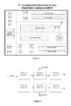
FIG. 1 is a flowchart showing some of the steps involved in 3rd Generation Construction process.
FIG. 2 is an example of a 3rd Generation Construction process block showing a first level grid and equipment arrangement.
FIG. 3 is a simple 3rd Generation Construction “block” layout.
FIG. 4 is a schematic of three exemplary process blocks (#1, #2 and #3) in an oil separation facility designed for the oil sands region of western Canada.
FIG. 5 is a schematic of a process block module layout elevation view, in which modules C, B and A are on one level, most likely ground level, with a fourth module D disposed atop module C.
FIG. 6 is a schematic of an alternative embodiment of a portion of an oil separation facility in which there are again three process blocks (#1, #2 and #3).
FIG. 7 is a schematic of the oil treating process block # 1 of FIG. 3, showing the three modules described above, plus two additional modules disposed in a second story.
FIG. 8 is a schematic of a 3rd Generation Modular facility having four process blocks, each of which has five modules.
DETAILED DESCRIPTION
In one aspect of preferred embodiments, the modular building system would further comprise a first command line coupling the A and B modules; a second command line coupling the B and C modules; and wherein the first and second command lines do not pass through the common piperack. In more preferred embodiments, the A, B, and C modules comprise at least, 5, at least 8, at least 12, or at least 15 modules. Preferably, at least two of the A, B and C process blocks are fluidly coupled by no more than five fluid lines, excluding utility lines. In still other preferred embodiments, a D module could be is stacked upon the C module, and a third fluid line could directly couple C and D modules.
Methods of laying out a 2nd Generation Modular facility are different in many respects from those used for laying out a 3rd Generation Modular facility. Whereas the former generally merely involves dividing up equipment for a given process among various modules, the latter preferably takes place in a five-step process as described below. It is contemplated that while traditional 2nd Generation Modular Construction can prefab about 50-60% of the work of a complex, multi-process facility, 3rd Generation Modular Construction can prefab up to about 90-95% of the work
Additional information for designing 3rd Generation Modular Construction facilities is included in the 3rd Generation Modular Execution Design Guide, which is included in this application. The Design Guide should be interpreted as exemplary of one or more preferred embodiments, and language indicating specifics (e.g. “shall be” or “must be”) should therefore be viewed merely as suggestive of one or more preferred embodiments. Where the Design Guide refers to confidential software, data or other design tools that are not included in this application, such software, data or other design tools are not deemed to be incorporated by reference. In the event there is a discrepancy between the Design Guide and this specification, the specification shall control.
FIG. 1 is a flow chart 100 showing steps in production of a 3rd Generation Construction process facility. In general there are three steps, as discussed below.
Step 101 is to identify the 3rd Generation Construction process facility configuration using process blocks. In this step the process lead typically separates the facilities into process “blocks”. This is best accomplished by developing a process block flow diagram. Each process block contains a distinct set of process systems. A process block will have one or more feed streams and one or more product streams. The process block will process the feed into different products as shown in.
Step 102 is to allocate a plot space for each 3rd Generation Construction process block. The plot space allocation requires the piping layout specialist to distribute the relevant equipment within each 3rd Generation Construction process block. At this phase of the project, only equipment estimated sizes and weights as provided by process/mechanical need be used to prepare each “block”. A 3rd Generation Construction process block equipment layout requires attention to location to assure effective integration with the piping, electrical and control distribution. In order to provide guidance to the layout specialist the following steps should be followed:
Step 102A is to obtain necessary equipment types, sizes and weights. It is important that equipment be sized so that it can fit effectively onto a module. Any equipment that has been sized and which can not fit effectively onto the module envelop needs to be evaluated by the process lead for possible resizing for effective module installation.
Step 102B is to establish an overall geometric area for the process block using a combination of transportable module dimensions. A first and second level should be identified using a grid layout where the grid identifies each module boundary within the process block.
Step 102C is to allocate space for the electrical and control distribution panels on the first level. FIG. 2 is an example of a 3rd Generation Construction process block first level grid and equipment arrangement. The E&I panels are sized to include the motor control centers and distributed instrument controllers and I/O necessary to energize and control the equipment, instrumentation, lighting and electrical heat tracing within the process block. The module which contains the E&I panels is designated the 3rd Generation primary process block module. Refer to E&I installation details for 3rd Generation module designs.
Step 102D is to group the equipment and instruments by primary systems using the process block PFDs.
Step 102E is to lay out each grouping of equipment by system onto the process block layout assuring that equipment does not cross module boundaries. The layout should focus on keeping the pumps located on the same module grid and level as the E&I distribution panels. This will assist with keeping the electrical power home run cables together. If it is not practical, the second best layout would be to have the pumps or any other motor close to the module with the E&I distribution panels. In addition, equipment should be spaced to assure effective operability, maintainability and safe access and egress.
The use of Fluor's Optimeyes™ is an effective tool at this stage of the project to assist with process block layouts.
Step 103 is to prepare a detailed equipment layout within Process Blocks to produce an integrated 3rd Generation facility. Each process block identified from step 2 is laid out onto a plot space assuring interconnects required between blocks are minimized. The primary interconnects are identified from the Process Flow Block diagram. Traditional interconnecting piperacks are preferably no longer needed or used. Pipeways are integrated into the module. A simple, typical 3rd Generation “block” layout is illustrated in FIG. 3.
Step 104 is to develop a 3rd Generation Module Configuration Table and power and control distribution plan, which combines process blocks for the overall facility to eliminate traditional interconnecting piperacks and reduce number of interconnects. A 3rd Generation module configuration table is developed using the above data. Templates can be used, and for example, a 3rd Generation power and control distribution plan can advantageously be prepared using the 3rd Generation power and control distribution architectural template.
Step 105 is to develop a 3rd Generation Modular Construction plan, which includes fully detailed process block modules on integrated multi-discipline basis. The final step for this phase of a project is to prepare an overall modular 3rd Generation Modular Execution plan, which can be used for setting the baseline to proceed to the next phase. It is contemplated that a 3rd Generation Modular Execution will require a different schedule than traditionally executed modular projects.
Many of the differences between the traditional 1st Generation and 2nd Generation Modular Construction and the 3rd Generation Modular Construction are set forth in Table 1 below, with references to the 3rd Generation Modular Execution Design Guide, which was filed with the parent provisional application:
TABLE 1
Traditional Truckable Modular
Activities Execution
3rd Gen Modular Execution
Layout & Steps are: Utilize structured work process to
Module 1. Develop Plot Plan using develop plot layout based on
Definition    equipment dimensions and development of Process Blocks with
   Process Flow Diagrams fully integrated equipment, piping,
   (PFDs). Optimize electrical and instrumentation/
   interconnects between controls, including the following
   equipment. steps:
2. Develop module boundaries 1. Identify the 3rd Generation
   using Plot Plan and Module    process facility configuration
   Transportation Envelop.    using process blocks using PFDs.
3. Develop detailed module 2. Allocate plot space for each 3rd
   layouts and interconnects    Generation process block.
   between modules and stick- 3. Detailed equipment layout within
   built portions of facilities    Process Blocks using 3rd
   utilizing a network of    Generation methodology to
   piperack/sleeperways and    eliminate traditional
   misc. supports.    interconnecting piperack and
4. Route electrical and controls    minimize or reduce interconnects
   cabling through    within Process Block modules.
   interconnecting racks and misc.    The layout builds up the Process
   supports to connect various    Block based on module blocks
   loads and instruments with    that conform to the
   satellite substation and racks.    transportation envelop.
Note: This results in a combination 4. Combine Process Blocks for
of 1st generation (piperack) and 2nd    overall facility to eliminate
generation (piperack with selected    traditional interconnecting
equipment) modules that fit the    piperacks and reduce number of
transportation envelop.    interconnects.
Ref.: Section 1.4 A 5. Develop a 3rd Generation
   Modular Construction plan,
   which includes fully detailed
   process block modules on
   integrated multi-discipline basis
Note: This results in an integrated
overall plot layout fully built up
from Module blocks that conform to
the transportation envelop.
Ref.: Section 2.2 thru 2.4
Piperacks/ Modularized piperacks and Eliminates the traditional
Sleeperways sleeperways, including cable tray modularized piperacks and
for field installation of sleeperways. Interconnects are
interconnects and home-run integrated into Process Block
cables. modules for shop installation.
Ref.: Section 2.5 Ref.: Section 2.2
Buildings Multiple standalone pre- Buildings are integrated into Process
engineered and stick built Block modules.
buildings based on discrete Ref: Section 3.3D
equipment housing.
Power Centralized switchgear and Decentralized MCC &
Distribution MCC at main and satellite switchgear integrated into
Architecture substations. Process Blocks located in
Individual home run feeders Primary Process Block module.
run from satellite substations to Feeders to loads are directly
drivers and loads via from decentralized MCCs and
interconnecting piperacks. switchgears located in the
Power cabling installed and Process Block without the need
terminated at site. for interconnecting piperack.
Power distribution cabling is
installed and terminated in
module shop for Process Block
interconnects with pre-
terminated cable connectors, or
coiled at module boundary for
site interconnection of cross
module feeders to loads within
Process Blocks using pre-
terminated cable connectors.
Ref.: Section 3.3E
Instrument Control cabinets are either Control cabinets are
and control centralized in satellite decentralized and integrated into
systems substations or randomly the Primary Process Block
distributed throughout process module.
facility. Close coupling of instruments to
Instrument locations are fallout locate all instruments for a
of piping and mechanical system on a single Process Block
layout. module to maximum extent
Vast majority of instrument practical.
cabling and termination is done Instrumentation cabling installed
in field for multiple cross and terminated in module shop.
module boundaries and stick- Process Block module
built portions via cable tray or interconnects utilize pre-installed
misc. supports installed on cabling pre-coiled at module
interconnecting piperacks. boundary for site connection
using pre-terminated cable
connectors.
Ref.: Section 3.3F
FIG. 4 is a schematic of three exemplary process blocks (#1, #2 and #3) in an oil separation facility designed for the oil sands region of western Canada. Here, process block # 1 has two modules (#1 and #2), process block # 2 has two modules (#3 and #4), and process block # 3 has only one module (#5). The dotted lines between modules indicate open sides of adjacent modules, whereas the solid lines around the modules indicate walls. The arrows show fluid and electrical couplings between modules. Thus, Drawing 1 shows only two one electrical line connection and one fluid line connection between modules # 1 and #2. Similarly, Drawing 1 shows no electrical line connections between process blocks #1 and 2, and only a single fluid line connection between those process blocks.
FIG. 5 is a schematic of a process block module layout elevation view, in which modules C, B and A are on one level, most likely ground level, with a fourth module D disposed atop module C. Although only two fluid couplings are shown, the Drawing should be understood to potentially include one or more additional fluid couplings, and one or more electrical and control couplings.
FIG. 6 is a schematic of an alternative embodiment of a portion of an oil separation facility in which there are again three process blocks (#1, #2 and #3). But here, process block # 1 has three modules (#1, #2, and #3), process block # 2 has two modules (#1 and #2), and process block # 3 has two additional modules (#1 and #2).
FIG. 7 is a schematic of the oil treating process block # 1 of FIG. 3, showing the three modules described above, plus two additional modules disposed in a second story.
FIG. 8 is a schematic of a 3rd Generation Modular facility having four process blocks, each of which has five modules. Although dimensions are not shown, each of the modules should be interpreted as having (a) a length of at least 15 meters, (b) a height greater than 4 meters, (c) a width greater than 4 meters, and (d) having open sides and/or ends where the modules within a given process block are positioned adjacent one another. In this particular example, the first and second process blocks are fluidly coupled by no more four fluid lines, excluding utility lines, four electrical lines, and two control lines. The first and third process blocks are connected by six fluid lines, excluding utility lines, and by one electrical and one control line.
Also in FIG. 8, a primary electrical supply from process block 1 fans out to three of the four modules of process block 3, and a control line from process block 1 fans out to all four of the modules of process block 3.
It should be apparent to those skilled in the art that many more modifications besides those already described are possible without departing from the inventive concepts herein. The inventive subject matter, therefore, is not to be restricted except in the spirit of the appended claims. Moreover, in interpreting both the specification and the claims, all terms should be interpreted in the broadest possible manner consistent with the context. In particular, the terms “comprises” and “comprising” should be interpreted as referring to elements, components, or steps in a non-exclusive manner, indicating that the referenced elements, components, or steps may be present, or utilized, or combined with other elements, components, or steps that are not expressly referenced. Where the specification claims refers to at least one of something selected from the group consisting of A, B, C . . . and N, the text should be interpreted as requiring only one element from the group, not A plus N, or B plus N, etc.

Claims (23)

What is claimed is:
1. A processing facility constructed at least in part by coupling first, second and third process blocks,
wherein the first process block is configured to carry out a first process, and includes at least first and second truckable 4-sided modules, and the second process block is configured to carry out a second process different from the first process, and includes at least third and fourth truckable 4sided modules, each of which has (a) a height greater than 4 meters and a width greater than 4 meters,
wherein the first module is abutted against the second module at a first side-to-side edge interface such that a person could walk from within the first module directly to within the second module, and wherein the first module is fluidly coupled with the second module across the side-to-side edge interface via a first set of fluid couplings disposed entirely within an envelope of the first and second process blocks, and
wherein the second module is further abutted against the third module at an end-to-end edge interface such that the person could walk from within the second module directly to within the third module, and wherein the second module is fluidly coupled with the third module across the end-to-end edge interface via a second set of fluid couplings disposed entirely within an envelope of the first and second process blocks.
2. The facility of claim 1, wherein each of the first, second, third and fourth modules has an open side.
3. The facility of claim 1, wherein the first and second modules are configured to minimize a number of connections in the first set of fluid couplings.
4. The facility of claim 3, wherein the first and second process blocks are configured to minimize a number of connections in the second set of fluid couplings.
5. The facility of claim 1, wherein the first and second modules are electrically coupled via a first set of electrical couplings at the first side-to-side edge interface.
6. The facility of claim 5, wherein the second and third modules are electrically coupled via a second set of electrical couplings at the end-to-end edge interface.
7. The facility of claim 1, wherein the fourth module is abutted against the third module at a second side-to-side interface, and is both fluidly and electrically coupled with the third module via paths that do not utilize an external pipe rack.
8. The facility of claim 1, wherein each of the modules is at least 15 meters long.
9. The facility of claim 1, wherein the process blocks collectively include equipment configured to extract oil from oil sands.
10. The facility of claim 1, wherein the second process block provides power to the first process block via one or more internal power lines in a manner that does not travel through an external pipe rack.
11. The facility of claim 10, wherein the first process block is configured to provide at least some of the power to the second process block.
12. The facility of claim 1, wherein the second process block provides steam to the first process block via one or more internal fluid lines in a manner that does not travel through an external pipe rack.
13. The facility of claim 1, wherein at least one of the process blocks includes an at least two story cooling tower.
14. The facility of claim 1, further comprising a control line that fans out to various modules within the first process block.
15. The facility of claim 1, wherein the first process block includes a personnel control area, and is controllably coupled to the second process block using fiber optics that passes through the side-to-side edge interface.
16. The facility of claim 1, wherein the process blocks collectively include at least one of a vessel, a compressor, a heat exchanger, a pump, a filter.
17. A modular building system comprising:
a first process block configured to carry out a first process and a second process block configured to carry out a second process different from the first process;
a first truckable 4-sided module of the first process block abutted to (1) a second truckable 4-sided module of the first process block in an end-to-end fashion at a first edge interface such that a person could walk from within the first module of the first process block directly to within the second module of the first process block, and (2) a first truckable 4-sided module of the second process block in a side-to-side fashion at a second edge interface such that a person could walk from within the first module of the first process block directly to within the first module of the second process block, with each of the modules having (a) a height greater than 4 meters and a width greater than 4 meters, and (b) at least one open side;
inter-module power distribution cabling having pre-terminated cable connectors at each of the first and second modules of the first process block and the first module of the second process block;
a first fluid line disposed entirely within an envelope of the first and second process blocks, and directly coupling the first and second modules of the first process block across the first edge interface;
a second fluid line disposed entirely within an envelope of the first and second process blocks, and directly coupling the first module of the first process block and first module of the second process block across the second edge interface; and
wherein the first and second fluid lines do not pass through a common external interconnecting piperack.
18. The modular building system of claim 17, further comprising:
a first command line coupling the first and second modules of the first process block across the first edge interface;
a second command line coupling the first module of the first process block and first module of the second process block across the second edge interface.
19. The modular building system of claim 17, further comprising an upper module that is stacked upon the first module of the second process block, and a third fluid line directly couples the upper module and the first module of the second process block.
20. The modular building system of claim 17, wherein the first and second modules of the first process block and the first module of the second process block, as well as at least seven other modules compose at least three process blocks.
21. The modular building system of claim 20, wherein first and second ones of the process blocks are fluidly coupled by no more than five fluid lines, excluding utility lines.
22. The modular building system of claim 17, wherein the first and second process blocks are rectangular.
23. The modular building system of claim 17, wherein the first process block is self-contained to carry out the first process.
US12/971,365 2009-12-18 2010-12-17 Modular Processing Facility Expired - Fee Related US8931217B2 (en)

Priority Applications (4)

Application Number Priority Date Filing Date Title
US12/971,365 US8931217B2 (en) 2009-12-18 2010-12-17 Modular Processing Facility
US14/527,425 US9376828B2 (en) 2009-12-18 2014-10-29 Modular processing facility
US14/747,727 US10458140B2 (en) 2009-12-18 2015-06-23 Modular processing facility
US15/440,812 US20170159305A1 (en) 2009-12-18 2017-02-23 Modular processing facility

Applications Claiming Priority (2)

Application Number Priority Date Filing Date Title
US28795609P 2009-12-18 2009-12-18
US12/971,365 US8931217B2 (en) 2009-12-18 2010-12-17 Modular Processing Facility

Related Child Applications (1)

Application Number Title Priority Date Filing Date
US14/527,425 Division US9376828B2 (en) 2009-12-18 2014-10-29 Modular processing facility

Publications (2)

Publication Number Publication Date
US20110146164A1 US20110146164A1 (en) 2011-06-23
US8931217B2 true US8931217B2 (en) 2015-01-13

Family

ID=44149114

Family Applications (3)

Application Number Title Priority Date Filing Date
US12/971,365 Expired - Fee Related US8931217B2 (en) 2009-12-18 2010-12-17 Modular Processing Facility
US14/527,425 Active US9376828B2 (en) 2009-12-18 2014-10-29 Modular processing facility
US14/747,727 Expired - Fee Related US10458140B2 (en) 2009-12-18 2015-06-23 Modular processing facility

Family Applications After (2)

Application Number Title Priority Date Filing Date
US14/527,425 Active US9376828B2 (en) 2009-12-18 2014-10-29 Modular processing facility
US14/747,727 Expired - Fee Related US10458140B2 (en) 2009-12-18 2015-06-23 Modular processing facility

Country Status (10)

Country Link
US (3) US8931217B2 (en)
EP (1) EP2516759B1 (en)
CN (2) CN106948490A (en)
AU (1) AU2010330872B9 (en)
BR (1) BR112012014815B1 (en)
CA (1) CA2724938C (en)
CL (1) CL2010001469A1 (en)
MX (1) MX337599B (en)
WO (1) WO2011075625A1 (en)
ZA (1) ZA201205131B (en)

Cited By (6)

* Cited by examiner, † Cited by third party
Publication number Priority date Publication date Assignee Title
US20150135636A1 (en) * 2013-11-18 2015-05-21 Red Flint Group, LLC Modular batch plant for granular products
US20160010916A1 (en) * 2013-03-27 2016-01-14 Woodside Energy Technologies Pty Ltd. Air-cooled modular lng production facility
US9810220B2 (en) 2013-06-04 2017-11-07 Fluor Technologies Corporation Method of transporting rotating equipment modularization
US10458140B2 (en) 2009-12-18 2019-10-29 Fluor Technologies Corporation Modular processing facility
US10539361B2 (en) 2012-08-22 2020-01-21 Woodside Energy Technologies Pty Ltd. Modular LNG production facility
US10787890B2 (en) 2017-10-20 2020-09-29 Fluor Technologies Corporation Integrated configuration for a steam assisted gravity drainage central processing facility

Families Citing this family (24)

* Cited by examiner, † Cited by third party
Publication number Priority date Publication date Assignee Title
CA2668253C (en) * 2008-06-03 2016-07-26 Richard F. Ablett Plant waste bio-product pomace extract concentrates and processes of producing same
CA2729457C (en) 2011-01-27 2013-08-06 Fort Hills Energy L.P. Process for integration of paraffinic froth treatment hub and a bitumen ore mining and extraction facility
CA2853070C (en) 2011-02-25 2015-12-15 Fort Hills Energy L.P. Process for treating high paraffin diluted bitumen
CA2931815C (en) 2011-03-01 2020-10-27 Fort Hills Energy L.P. Process and unit for solvent recovery from solvent diluted tailings derived from bitumen froth treatment
CA2806891C (en) 2011-03-04 2014-12-09 Fort Hills Energy L.P. A solvent treatment process for treating bitumen froth with axi-symmetric distribution of separator feed
CA2735311C (en) 2011-03-22 2013-09-24 Fort Hills Energy L.P. Process for direct steam injection heating of oil sands bitumen froth
CA2737410C (en) 2011-04-15 2013-10-15 Fort Hills Energy L.P. Heat recovery for bitumen froth treatment plant integration with sealed closed-loop cooling circuit
CA2848254C (en) 2011-04-28 2020-08-25 Fort Hills Energy L.P. Recovery of solvent from diluted tailings by feeding a desegregated flow to nozzles
CA2857718C (en) 2011-05-04 2015-07-07 Fort Hills Energy L.P. Turndown process for a bitumen froth treatment operation
CA2832269C (en) 2011-05-18 2017-10-17 Fort Hills Energy L.P. Temperature control of bitumen froth treatment process with trim heating of solvent streams
US9603281B2 (en) * 2012-03-12 2017-03-21 Compass Datacenters, Llc Truly modular building datacenter facility
DE102013201171A1 (en) 2013-01-24 2014-07-24 Infracor Gmbh Method and system for using an industrial property
WO2014164692A2 (en) 2013-03-13 2014-10-09 Vestigium Engineering, Inc. Modular system for extracting hydrocarbons from subterranean volumes and associated methods
CA2912273C (en) * 2014-02-07 2018-05-01 Kemex Ltd. Detachable pipe rack module with detachable connectors for use in a processing facility
US20180036709A1 (en) * 2014-05-27 2018-02-08 Portable GTL Systems, LLC Portable fuel synthesizer
US9453333B2 (en) 2014-08-27 2016-09-27 Ronald Porter System and method of fabricating and assembling industrial plant modules for industrial plant construction
WO2016181029A1 (en) * 2015-05-13 2016-11-17 Outotec (Finland) Oy A flotation plant and its uses and methods of maintenance of a flotation plant
US20170216766A1 (en) * 2016-02-01 2017-08-03 Fluor Technologies Corporation Modular systems and methods for developing gas fields
WO2018109941A1 (en) * 2016-12-16 2018-06-21 ユニ・チャーム株式会社 Absorbent article manufacturing factory
US20180220552A1 (en) * 2017-01-31 2018-08-02 Fluor Technologies Corporation Modular processing facility with distributed cooling systems
WO2019089694A1 (en) * 2017-10-31 2019-05-09 Fluor Technologies Corporation Cracker modular processing facility
US11952769B2 (en) 2018-03-02 2024-04-09 Modular Plant Solutions Llc Modular process plant structural system
EP4006668A1 (en) * 2020-11-26 2022-06-01 ABB Schweiz AG Resource management for modular plants
CN113837712B (en) * 2021-08-10 2023-08-22 中国海洋石油集团有限公司 Large land liquefied natural gas production process module dividing and arranging method

Citations (15)

* Cited by examiner, † Cited by third party
Publication number Priority date Publication date Assignee Title
US3925679A (en) * 1973-09-21 1975-12-09 Westinghouse Electric Corp Modular operating centers and methods of building same for use in electric power generating plants and other industrial and commercial plants, processes and systems
US4267822A (en) * 1978-11-08 1981-05-19 Grumman Energy Systems, Inc. Integrated solar energy system
US4452312A (en) * 1981-02-23 1984-06-05 Alteliers et Chantiers de Chantiers de Bretagne-ACB Modular undersea oil production plant
US4457116A (en) * 1980-06-12 1984-07-03 Kump Ernest J Space module
US5474411A (en) * 1992-06-05 1995-12-12 Nukem Gmbh Multistory structure for chemical plants
US6176046B1 (en) * 1998-11-24 2001-01-23 Northstar Industries, Inc. Portable, pre-manufactured, modular natural gas delivery stations
US6308465B1 (en) * 1999-06-21 2001-10-30 Equitech, Inc. Systems and utility modules for buildings
WO2003031012A1 (en) 2001-09-14 2003-04-17 Precision Systems Engineering Modular oil refinery
US6581698B1 (en) 1998-08-19 2003-06-24 Bentec Gmbh Drilling & Oilfield Systems Drilling device and method for drilling a well
US6786051B2 (en) * 2001-10-26 2004-09-07 Vulcan Advanced Mobile Power Systems, L.L.C. Trailer mounted mobile power system
US20050241823A1 (en) 2004-05-03 2005-11-03 Beato Christopher L Modular drill system requiring limited field assembly and limited equipment support
US20060124354A1 (en) * 2004-11-19 2006-06-15 Baker Hughes Incorporated Modular drilling apparatus with power and/or data transmission
CA2596139A1 (en) 2006-08-07 2008-02-07 Mark K. Gaalswyk Self-contained deployable automatic factory built ethanol production plant
US20080127662A1 (en) 2006-06-19 2008-06-05 Stanfield Michael E Method, System, and Apparatus for Modular Central Plant
US8151537B2 (en) * 2008-07-29 2012-04-10 Green Horizon Manufacturing Llc Method for deploying cooperating prefabricated structures

Family Cites Families (40)

* Cited by examiner, † Cited by third party
Publication number Priority date Publication date Assignee Title
US3274745A (en) 1962-07-02 1966-09-27 Foster Wheeler Corp Process for constructing a petroleum refinery
US3643389A (en) * 1970-06-30 1972-02-22 Ibm Modular electrical enclosure
US3707165A (en) 1970-08-10 1972-12-26 Joel S Stahl Plastic plumbing wall
US4055050A (en) 1976-02-11 1977-10-25 Vladimir Borisovich Kozlov Apparatus for and method of regasifying liquefied natural gas
US4527981A (en) * 1978-05-15 1985-07-09 Chisum Finis L Method and apparatus for designing a log home
GB1604759A (en) * 1978-05-31 1981-12-16 Kump E J Space module
FR2475505A1 (en) 1980-02-08 1981-08-14 Veco Sarl CONTAINER FOR TRANSPORTING A CHAIN OF MANUFACTURE, TREATMENT, EXPERIMENTATION, EXAMINATION OR THE LIKE
FR2563559A1 (en) * 1984-04-25 1985-10-31 Wieczorek Julien Shelters and protective systems for petroleum and petrochemical installations
FR2638196B1 (en) 1988-10-26 1991-01-25 Roche Jean METHOD AND DEVICE FOR MODULAR CONSTRUCTION OF INDUSTRIAL BUILDINGS
US4992669A (en) 1989-02-16 1991-02-12 Parmley Daniel W Modular energy system
US6116050A (en) 1998-12-04 2000-09-12 Ipsi Llc Propane recovery methods
IL146775A0 (en) * 1999-05-27 2002-07-25 Tno Method for the purification of a liquid by membrane distillation, in particular for the production of desalinated water from seawater or brackish water or process water
NO312736B1 (en) 2000-02-10 2002-06-24 Sinvent As Method and plant for cooling and possibly liquefying a product gas
JP2001325016A (en) * 2000-05-15 2001-11-22 Denso Corp Production method and production system
DE10149316A1 (en) 2001-10-05 2003-04-17 Univ Albert Ludwigs Freiburg Micro-fluid channel system, to separate solids from suspensions for on-the-chip analysis, comprises an inflow reservoir and a stretch with an elbow curve leading to at least two outflow reservoirs
US7051553B2 (en) 2002-05-20 2006-05-30 Floor Technologies Corporation Twin reflux process and configurations for improved natural gas liquids recovery
US8621786B2 (en) * 2003-02-13 2014-01-07 Wei Chak Joseph Lam Efficient layout and design of production facility
US7264694B2 (en) * 2004-01-29 2007-09-04 Oil-Tech, Inc. Retort heating apparatus and methods
ES2284429T1 (en) 2004-07-01 2007-11-16 Ortloff Engineers, Ltd LICUATED NATURAL GAS PROCESSING.
US7647976B2 (en) 2006-04-21 2010-01-19 Maoz Betzer Tsilevich System and method for steam-assisted gravity drainage (SAGD)-based heavy oil well production
US20080178537A1 (en) 2007-01-31 2008-07-31 Spangler John M Portable modular manufacturing system
RU2007119695A (en) 2007-05-28 2008-12-10 Николай Иванович Григорьев (RU) MODULAR BOILER ROOM
US20100132390A1 (en) 2008-09-18 2010-06-03 Multistack Llc Variable four pipe heatpump chiller
US8157003B2 (en) 2008-12-18 2012-04-17 Stillwater Energy Group, Llc Integrated carbon management system for petroleum refining
SG172325A1 (en) 2008-12-23 2011-07-28 Xoma Technology Ltd Flexible manufacturing system
US8535419B2 (en) 2009-04-01 2013-09-17 Zephyr Gas Services Llc Modular amine plant
JP5391836B2 (en) 2009-05-29 2014-01-15 株式会社日立製作所 Module structure and plant construction method
US8070389B2 (en) * 2009-06-11 2011-12-06 Technip France Modular topsides system and method having dual installation capabilities for offshore structures
US20170159305A1 (en) 2009-12-18 2017-06-08 Fluor Technologies Corporation Modular processing facility
AU2014202657B2 (en) 2009-12-18 2016-07-07 Fluor Technologies Corporation Modular processing facility
CA2724938C (en) 2009-12-18 2017-01-24 Fluor Technologies Corporation Modular processing facility
CA2729457C (en) 2011-01-27 2013-08-06 Fort Hills Energy L.P. Process for integration of paraffinic froth treatment hub and a bitumen ore mining and extraction facility
AU2011357584A1 (en) 2011-01-28 2013-08-01 1Nsite Technologies Ltd. Modular transportable system for SAGD process
US20130066772A1 (en) 2011-09-09 2013-03-14 Chuyu Xiong Multi-factor and multi-channel id authentication and transaction control and multi-option payment system and method
US9670113B2 (en) 2012-07-09 2017-06-06 Siluria Technologies, Inc. Natural gas processing and systems
AU2012216352B2 (en) 2012-08-22 2015-02-12 Woodside Energy Technologies Pty Ltd Modular LNG production facility
CA3225180A1 (en) 2014-01-09 2015-07-16 Lummus Technology Llc Oxidative coupling of methane implementations for olefin production
US20170216766A1 (en) 2016-02-01 2017-08-03 Fluor Technologies Corporation Modular systems and methods for developing gas fields
CA3015351A1 (en) 2016-02-26 2017-08-31 Fluor Technologies Corporation Modular processing facility
US20180220552A1 (en) 2017-01-31 2018-08-02 Fluor Technologies Corporation Modular processing facility with distributed cooling systems

Patent Citations (17)

* Cited by examiner, † Cited by third party
Publication number Priority date Publication date Assignee Title
US3925679A (en) * 1973-09-21 1975-12-09 Westinghouse Electric Corp Modular operating centers and methods of building same for use in electric power generating plants and other industrial and commercial plants, processes and systems
US4267822A (en) * 1978-11-08 1981-05-19 Grumman Energy Systems, Inc. Integrated solar energy system
US4457116A (en) * 1980-06-12 1984-07-03 Kump Ernest J Space module
US4452312A (en) * 1981-02-23 1984-06-05 Alteliers et Chantiers de Chantiers de Bretagne-ACB Modular undersea oil production plant
US5474411A (en) * 1992-06-05 1995-12-12 Nukem Gmbh Multistory structure for chemical plants
US6581698B1 (en) 1998-08-19 2003-06-24 Bentec Gmbh Drilling & Oilfield Systems Drilling device and method for drilling a well
US6176046B1 (en) * 1998-11-24 2001-01-23 Northstar Industries, Inc. Portable, pre-manufactured, modular natural gas delivery stations
US6308465B1 (en) * 1999-06-21 2001-10-30 Equitech, Inc. Systems and utility modules for buildings
WO2003031012A1 (en) 2001-09-14 2003-04-17 Precision Systems Engineering Modular oil refinery
US6786051B2 (en) * 2001-10-26 2004-09-07 Vulcan Advanced Mobile Power Systems, L.L.C. Trailer mounted mobile power system
US20050241823A1 (en) 2004-05-03 2005-11-03 Beato Christopher L Modular drill system requiring limited field assembly and limited equipment support
US20060124354A1 (en) * 2004-11-19 2006-06-15 Baker Hughes Incorporated Modular drilling apparatus with power and/or data transmission
US20080127662A1 (en) 2006-06-19 2008-06-05 Stanfield Michael E Method, System, and Apparatus for Modular Central Plant
CA2596139A1 (en) 2006-08-07 2008-02-07 Mark K. Gaalswyk Self-contained deployable automatic factory built ethanol production plant
US20080029447A1 (en) 2006-08-07 2008-02-07 Gaalswyk Mark K Self-contained deployable automatic factory built ethanol production plant
US8097451B2 (en) * 2006-08-07 2012-01-17 Mark K Gaalswyk Self-contained deployable automatic factory built ethanol production plant
US8151537B2 (en) * 2008-07-29 2012-04-10 Green Horizon Manufacturing Llc Method for deploying cooperating prefabricated structures

Cited By (10)

* Cited by examiner, † Cited by third party
Publication number Priority date Publication date Assignee Title
US10458140B2 (en) 2009-12-18 2019-10-29 Fluor Technologies Corporation Modular processing facility
US10539361B2 (en) 2012-08-22 2020-01-21 Woodside Energy Technologies Pty Ltd. Modular LNG production facility
US20160010916A1 (en) * 2013-03-27 2016-01-14 Woodside Energy Technologies Pty Ltd. Air-cooled modular lng production facility
US10060670B2 (en) * 2013-03-27 2018-08-28 Woodside Energy Technologies Pty Ltd. Air-cooled modular LNG production facility
US9810220B2 (en) 2013-06-04 2017-11-07 Fluor Technologies Corporation Method of transporting rotating equipment modularization
US20150135636A1 (en) * 2013-11-18 2015-05-21 Red Flint Group, LLC Modular batch plant for granular products
US9427782B2 (en) * 2013-11-18 2016-08-30 Red Flint Group, LLC Modular batch plant for granular products
US10005106B2 (en) 2013-11-18 2018-06-26 Red Flint Group, LLC Modular batch plant for granular products
US10155251B2 (en) * 2013-11-18 2018-12-18 Red Flint Group, LLC Modular batch plant for granular products
US10787890B2 (en) 2017-10-20 2020-09-29 Fluor Technologies Corporation Integrated configuration for a steam assisted gravity drainage central processing facility

Also Published As

Publication number Publication date
BR112012014815B1 (en) 2020-01-07
CN102859087A (en) 2013-01-02
AU2010330872B9 (en) 2018-09-06
MX2012007092A (en) 2012-07-30
CL2010001469A1 (en) 2012-04-09
EP2516759A4 (en) 2014-11-05
CA2724938C (en) 2017-01-24
WO2011075625A1 (en) 2011-06-23
EP2516759A1 (en) 2012-10-31
AU2010330872A1 (en) 2012-07-05
CA2724938A1 (en) 2011-06-18
EP2516759B1 (en) 2020-02-12
BR112012014815A2 (en) 2016-08-16
US20150143775A1 (en) 2015-05-28
US9376828B2 (en) 2016-06-28
US10458140B2 (en) 2019-10-29
US20110146164A1 (en) 2011-06-23
MX337599B (en) 2016-03-11
CN106948490A (en) 2017-07-14
AU2010330872B2 (en) 2014-04-24
ZA201205131B (en) 2014-12-23
US20150292223A1 (en) 2015-10-15

Similar Documents

Publication Publication Date Title
US10458140B2 (en) Modular processing facility
US20170159305A1 (en) Modular processing facility
JP6621335B2 (en) Nuclear power plant and 3D-CAD system for design
AU2014202657B2 (en) Modular processing facility
Bedair Rational design of pipe racks used for oil sands and petrochemical facilities
CA3015351A1 (en) Modular processing facility
US20180220552A1 (en) Modular processing facility with distributed cooling systems
US20210180862A1 (en) Cracker modular processing facility
WO2011130000A1 (en) System comprising a plurality of distribution devices and distribution device
US20140099064A1 (en) System comprising a plurality of distribution devices and distribution device
CN202767578U (en) Modular data center
NO20190945A1 (en) Metal structure for supporting fluid ducts and industrial facility comprising such a metal structure
CN213418052U (en) Novel pipe rack
Bedair Cost effective modularization strategies for industrial facilities used in mega oil & gas projects
Jaquith et al. Modular engine room design and construction for the strategic sealift ships
US20230401502A1 (en) Modular data center
WO2024069924A1 (en) Module for configuring plant and method for constructing plant
WO2018132866A1 (en) High-density modular data centre
CN114207970A (en) Method for manufacturing power transformation equipment and power transformation equipment
Chrzanowski et al. TFTR modifications for DT shielding
Morita et al. Advanced Construction Technology for Shika Nuclear Power Station Unit No. 2 of the Hokuriku Electric Power Company
JPH04244697A (en) Module type generating equipment
JPS5820528B2 (en) Cable arrangement structure

Legal Events

Date Code Title Description
STCF Information on status: patent grant

Free format text: PATENTED CASE

AS Assignment

Owner name: FLUOR TECHNOLOGIES CORPORATION, CALIFORNIA

Free format text: ASSIGNMENT OF ASSIGNORS INTEREST;ASSIGNORS:HANEY, FRED;DONOVAN, GARY;ROTH, TODD;AND OTHERS;SIGNING DATES FROM 20151001 TO 20151007;REEL/FRAME:036863/0382

MAFP Maintenance fee payment

Free format text: PAYMENT OF MAINTENANCE FEE, 4TH YEAR, LARGE ENTITY (ORIGINAL EVENT CODE: M1551)

Year of fee payment: 4

FEPP Fee payment procedure

Free format text: MAINTENANCE FEE REMINDER MAILED (ORIGINAL EVENT CODE: REM.); ENTITY STATUS OF PATENT OWNER: LARGE ENTITY

LAPS Lapse for failure to pay maintenance fees

Free format text: PATENT EXPIRED FOR FAILURE TO PAY MAINTENANCE FEES (ORIGINAL EVENT CODE: EXP.); ENTITY STATUS OF PATENT OWNER: LARGE ENTITY

STCH Information on status: patent discontinuation

Free format text: PATENT EXPIRED DUE TO NONPAYMENT OF MAINTENANCE FEES UNDER 37 CFR 1.362

FP Lapsed due to failure to pay maintenance fee

Effective date: 20230113