US892884A - Means for attaching pads to boots and shoes. - Google Patents
Means for attaching pads to boots and shoes. Download PDFInfo
- Publication number
- US892884A US892884A US41890508A US1908418905A US892884A US 892884 A US892884 A US 892884A US 41890508 A US41890508 A US 41890508A US 1908418905 A US1908418905 A US 1908418905A US 892884 A US892884 A US 892884A
- Authority
- US
- United States
- Prior art keywords
- pad
- flange
- notch
- plate
- boots
- Prior art date
- Legal status (The legal status is an assumption and is not a legal conclusion. Google has not performed a legal analysis and makes no representation as to the accuracy of the status listed.)
- Expired - Lifetime
Links
- 239000002184 metal Substances 0.000 description 2
- 239000010985 leather Substances 0.000 description 1
- 230000004048 modification Effects 0.000 description 1
- 238000012986 modification Methods 0.000 description 1
Images
Classifications
-
- A—HUMAN NECESSITIES
- A43—FOOTWEAR
- A43B—CHARACTERISTIC FEATURES OF FOOTWEAR; PARTS OF FOOTWEAR
- A43B21/00—Heels; Top-pieces or top-lifts
- A43B21/36—Heels; Top-pieces or top-lifts characterised by their attachment; Securing devices for the attaching means
- A43B21/37—Heels; Top-pieces or top-lifts characterised by their attachment; Securing devices for the attaching means by hook-shaped or bent attaching means
Definitions
- Elastic pads as worn with boots and shoes are usually attached by a screw and in at taching them a screw-driver is necessary. Owingto the screw wearing away with the pad it is liable to loose its hold on the pad before the pad is fully worn away as well as become so worn as to be difficult to remove when requiring to fix a new pad.
- This invention has for its object to dispense with the screw and to provide improved facilities whereby the pad may be applied without tools of any kind, and when so applied will allow of being fully worn away without risk of detachment.
- I provide the boot or shoe with a fixed metal plate having a central orifice and its inner edge forming a lip. In such lip is a notch or recess. I also provide the pad with a flanged stud made integral with the pad and in the flange of the stud is a notch or recess similar to that in the plate.
- the flange of the stud on the pad By causing the flange of the stud on the pad to engage the lip of the plate by means of the notches, and then rotating the pad, the flange passes, by degrees, behind the lip of the plate, and eventually becomes locked by the plate in the space or cavity between the lip and the boot or shoe.
- the plate will either be dished or turned upwards at its outer edge, or packed with a washer, or the first layer of leather of the boot or shoe will be formed with a recess or orifice.
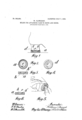
- Figure 1 illustrates a ladys shoe heel with the in vention (shown in section) applied thereto.
- Fig. 2 illustrates a plan of the pad.
- Fig. 3 illustrates a cross section.
- Fig. 4 illustrates a plan of the device used with the pad and permanently fixed to the heel.
- Fig. 5 illustrates pers ectively the manner in which the pad is app ied to the heel.
- Fig. 6 illustrates a modification.
- flange 1 formed integral with the pad, and c the notch in the flange.
- (Z is the plate secured to the boot or shoe and formed with a notch e in its inner edge.
- the plate is secured to the boot or shoe by sprigs or nails passing through its outer flange.
- the notches c and e are preferably of the same size and shape. There may be two or more notches in the plate and flange, but one will usually serve.
- the user grips and presses back the outer edge in order to see the position of the notch see Fig. 5.
- the operator then causes one side of the notch c to take under the opposite side of the notch e in the plate (Z.
- the engagement of the flange and lip being thus started, the further rotation of the pad causes the flange to gradually pass behind the lip of the plate until the other edge of the notch 0 passes below the edge of the notch e, when the whole ofthe flange lies behind the plate and is locked in the cavity between the plate and the heel.
- the pad is free to be rotated to any position and in all positions it is secure against detachment with ordinary wear.
- the pad By again gripping and pressing back the edge of the pad and spring ing the edge of the notch c in the flange I) over the side of the notch e and then rotating the flange, the pad may be readily detached from the plate, thus enabling a partially worn pad to be readily replaced by a new pad.
- flange instead of the beveled sides of the notch in the pad stud. flange being parallel with each other they may be arranged at right angles to each other as shown in Fig. 6, this form of the notch affording the advantage of pad, and said flange having in its edges a three-sided notch, each of the faces of the two opposite sides of which lies in a plane diagonal to the plane of the flange, substantially as set forth.
Landscapes
- Footwear And Its Accessory, Manufacturing Method And Apparatuses (AREA)
Description
No. 892,884. PATENTED JULY 7, 1908.
W. PLOWRIGHT. MEANS FOR ATTAGHING PADS T0 BOOTS AND SHOES.
APPLICATION FILED MAB. 2, 1908.
Wm JW/m UNITED STATES PATENT ()FFICE.
WILLIAM PLOWRIGHT, OF MANCHESTER, ENGLAND.
MEANS FOR ATTACHING PADS TO BOOTS AND SHOES.
Application filed March 2, 1908.
To all whom it may concern:
Be it known that 1, WILLIAM PLOWRIGHT, a subject of the King of Great Britain and Ireland, and resident of Manchester, England, have invented certain new and useful Improvements in or Relating to Means for Attaching Pads to Boots and Shoes, of which the following is a specification.
Elastic pads as worn with boots and shoes are usually attached by a screw and in at taching them a screw-driver is necessary. Owingto the screw wearing away with the pad it is liable to loose its hold on the pad before the pad is fully worn away as well as become so worn as to be difficult to remove when requiring to fix a new pad.
This invention has for its object to dispense with the screw and to provide improved facilities whereby the pad may be applied without tools of any kind, and when so applied will allow of being fully worn away without risk of detachment.
According to the invention, I provide the boot or shoe with a fixed metal plate having a central orifice and its inner edge forming a lip. In such lip is a notch or recess. I also provide the pad with a flanged stud made integral with the pad and in the flange of the stud is a notch or recess similar to that in the plate.
By causing the flange of the stud on the pad to engage the lip of the plate by means of the notches, and then rotating the pad, the flange passes, by degrees, behind the lip of the plate, and eventually becomes locked by the plate in the space or cavity between the lip and the boot or shoe. To produce the necessary cavity for the flange, the plate will either be dished or turned upwards at its outer edge, or packed with a washer, or the first layer of leather of the boot or shoe will be formed with a recess or orifice.
Upon the accompanying drawing, Figure 1 illustrates a ladys shoe heel with the in vention (shown in section) applied thereto. Fig. 2 illustrates a plan of the pad. Fig. 3 illustrates a cross section. Fig. 4 illustrates a plan of the device used with the pad and permanently fixed to the heel. Fig. 5 illustrates pers ectively the manner in which the pad is app ied to the heel. Fig. 6 illustrates a modification.
In all the views a is the pad, I; the stud Specification of Letters Patent.
Patented. July 7, 1908.
Serial No. 418,905.
with flange 1) formed integral with the pad, and c the notch in the flange.
(Z is the plate secured to the boot or shoe and formed with a notch e in its inner edge. The plate is secured to the boot or shoe by sprigs or nails passing through its outer flange. The notches c and e are preferably of the same size and shape. There may be two or more notches in the plate and flange, but one will usually serve.
In applying the pad the user grips and presses back the outer edge in order to see the position of the notch see Fig. 5. The operator then causes one side of the notch c to take under the opposite side of the notch e in the plate (Z. The engagement of the flange and lip being thus started, the further rotation of the pad causes the flange to gradually pass behind the lip of the plate until the other edge of the notch 0 passes below the edge of the notch e, when the whole ofthe flange lies behind the plate and is locked in the cavity between the plate and the heel. When so held to the heel the pad is free to be rotated to any position and in all positions it is secure against detachment with ordinary wear. By again gripping and pressing back the edge of the pad and spring ing the edge of the notch c in the flange I) over the side of the notch e and then rotating the flange, the pad may be readily detached from the plate, thus enabling a partially worn pad to be readily replaced by a new pad.
To facilitate the starting of the stud flange when engaging the lip of the plate, the sides of the notch in the flange are beveled, see Fig. 1.
Instead of the beveled sides of the notch in the pad stud. flange being parallel with each other they may be arranged at right angles to each other as shown in Fig. 6, this form of the notch affording the advantage of pad, and said flange having in its edges a three-sided notch, each of the faces of the two opposite sides of which lies in a plane diagonal to the plane of the flange, substantially as set forth.
. 2. An elastic pad for boots and shoes pro vided with an integral flanged stud, the flange lying at right angles to the stud and parallel with the plane of the wearing surface of the pad, and said flange having in its edge a three-sided notch, each of the faces of the two opposite sides of which lies in a plane diagonal to the plane of the flange, in co1n bination with a thin metal plate having a central orifice slightly less in diameter than the flange of the pad but slightly larger in diameter than the stud, and the inner edge of such plate having a three-sided, rightangled notch with which when rotated the padstud flange may engage by one of the edges of its notch and pass behind the plate, substantially as herein set forth In witness whereof I have hereunto set my hand in the presence of two witnesses.
WILLIAM PLOl/VRIGHT. \(Vitnesses F. O. PENNINGTON, P. D. BAILEY.
Priority Applications (1)
| Application Number | Priority Date | Filing Date | Title |
|---|---|---|---|
| US41890508A US892884A (en) | 1908-03-02 | 1908-03-02 | Means for attaching pads to boots and shoes. |
Applications Claiming Priority (1)
| Application Number | Priority Date | Filing Date | Title |
|---|---|---|---|
| US41890508A US892884A (en) | 1908-03-02 | 1908-03-02 | Means for attaching pads to boots and shoes. |
Publications (1)
| Publication Number | Publication Date |
|---|---|
| US892884A true US892884A (en) | 1908-07-07 |
Family
ID=2961313
Family Applications (1)
| Application Number | Title | Priority Date | Filing Date |
|---|---|---|---|
| US41890508A Expired - Lifetime US892884A (en) | 1908-03-02 | 1908-03-02 | Means for attaching pads to boots and shoes. |
Country Status (1)
| Country | Link |
|---|---|
| US (1) | US892884A (en) |
-
1908
- 1908-03-02 US US41890508A patent/US892884A/en not_active Expired - Lifetime
Similar Documents
| Publication | Publication Date | Title |
|---|---|---|
| US456677A (en) | Frank p | |
| US892884A (en) | Means for attaching pads to boots and shoes. | |
| US1037741A (en) | Balance-cock. | |
| US1090333A (en) | Shoe-lacing device. | |
| US921134A (en) | Fastening device. | |
| CA120261A (en) | Fastener for boots, shoes, etc. | |
| US1037742A (en) | Hair-spring-stud-holding means. | |
| US362188A (en) | John g | |
| US407860A (en) | Heel attachment | |
| US263110A (en) | Lacing-stud set or punch | |
| US2504A (en) | Daniel hodgman | |
| US239186A (en) | Chaelbs neil | |
| US518682A (en) | Louts weyand | |
| US1108975A (en) | Shoe-heel. | |
| US1280836A (en) | Adjustable shoe-heel. | |
| US238362A (en) | Sidney cbowley | |
| USD55528S (en) | Design for the sole of a rubber boot or shoe | |
| US469660A (en) | Julius erbeau | |
| US424348A (en) | Brake-shoe | |
| US117876A (en) | Improvement in shoe-fastenings | |
| USD48041S (en) | Design for an india-rubber sole-pad por boots and shoes | |
| USD23091S (en) | Design for a stopper-plug | |
| US783445A (en) | Finger-ring. | |
| US440710A (en) | William h | |
| USD49623S (en) | Design for a frame for knife-polishing machines |