US8926312B2 - Detachable threaded rod for use in a mold - Google Patents
Detachable threaded rod for use in a mold Download PDFInfo
- Publication number
- US8926312B2 US8926312B2 US13/923,272 US201313923272A US8926312B2 US 8926312 B2 US8926312 B2 US 8926312B2 US 201313923272 A US201313923272 A US 201313923272A US 8926312 B2 US8926312 B2 US 8926312B2
- Authority
- US
- United States
- Prior art keywords
- hole
- threaded rod
- mating
- screw
- molding portion
- Prior art date
- Legal status (The legal status is an assumption and is not a legal conclusion. Google has not performed a legal analysis and makes no representation as to the accuracy of the status listed.)
- Expired - Fee Related
Links
Images


Classifications
-
- B—PERFORMING OPERATIONS; TRANSPORTING
- B29—WORKING OF PLASTICS; WORKING OF SUBSTANCES IN A PLASTIC STATE IN GENERAL
- B29C—SHAPING OR JOINING OF PLASTICS; SHAPING OF MATERIAL IN A PLASTIC STATE, NOT OTHERWISE PROVIDED FOR; AFTER-TREATMENT OF THE SHAPED PRODUCTS, e.g. REPAIRING
- B29C45/00—Injection moulding, i.e. forcing the required volume of moulding material through a nozzle into a closed mould; Apparatus therefor
- B29C45/17—Component parts, details or accessories; Auxiliary operations
- B29C45/26—Moulds
- B29C45/2618—Moulds having screw-threaded mould walls
-
- B—PERFORMING OPERATIONS; TRANSPORTING
- B29—WORKING OF PLASTICS; WORKING OF SUBSTANCES IN A PLASTIC STATE IN GENERAL
- B29C—SHAPING OR JOINING OF PLASTICS; SHAPING OF MATERIAL IN A PLASTIC STATE, NOT OTHERWISE PROVIDED FOR; AFTER-TREATMENT OF THE SHAPED PRODUCTS, e.g. REPAIRING
- B29C45/00—Injection moulding, i.e. forcing the required volume of moulding material through a nozzle into a closed mould; Apparatus therefor
- B29C45/17—Component parts, details or accessories; Auxiliary operations
- B29C45/1742—Mounting of moulds; Mould supports
-
- Y—GENERAL TAGGING OF NEW TECHNOLOGICAL DEVELOPMENTS; GENERAL TAGGING OF CROSS-SECTIONAL TECHNOLOGIES SPANNING OVER SEVERAL SECTIONS OF THE IPC; TECHNICAL SUBJECTS COVERED BY FORMER USPC CROSS-REFERENCE ART COLLECTIONS [XRACs] AND DIGESTS
- Y10—TECHNICAL SUBJECTS COVERED BY FORMER USPC
- Y10S—TECHNICAL SUBJECTS COVERED BY FORMER USPC CROSS-REFERENCE ART COLLECTIONS [XRACs] AND DIGESTS
- Y10S425/00—Plastic article or earthenware shaping or treating: apparatus
- Y10S425/808—Lens mold
Definitions
- the present disclosure relates to molds and, particularly, to a detachable threaded rod for use in a mold.
- Molds may include a threaded rod to mold internal threads in workpieces. To mold different sizes of internal threads, the fully threaded rod needs to be replaced with another suitable one, which is complicated.
- FIG. 1 is an isometric view of a detachable threaded rod in accordance with an exemplary embodiment.
- FIG. 2 is an exploded view of the detachable threaded rod of FIG. 1 .
- FIG. 3 is a cross-sectional view of the detachable threaded rod taken along a line III-III of FIG. 1 .
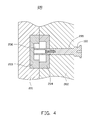
- FIG. 4 is a cross-sectional view of an injection mold using the detachable threaded rod of FIG. 1 .
- FIGS. 1-3 show a detachable threaded rod 100 , according to an exemplary embodiment.
- the detachable threaded rod 100 includes an operation portion 10 , a molding portion 20 , and a screw 30 .
- the detachable threaded rod 100 is configured for molding internal threads of a workpiece, such as a lens holder (not shown).
- the operation portion 10 includes a base 11 and a rod part 12 extending from the base 11 .
- An external diameter of the base 11 is greater than an external diameter of the rod part 12 .
- the base 11 defines a position recess 111 facing away from the rod part 12 .
- the rod part 12 defines a mating hole 121 facing away from the base 11 .
- the mating hole 121 forms a bottom surface 122 , which is substantially parallel with an end surface of the rod part 12 .
- the rod part 12 defines a screw hole 123 on the bottom surface 122 .
- a cross-section of the mating hole 121 is substantially rectangular.
- a sectional area of the screw hole 123 is less than a sectional area of the mating hole 121 .
- the molding portion 20 includes a front end 21 , a rear end 22 opposite to the front end 21 , and a side surface 23 connected between the front end 21 and the rear end 22 .
- the molding portion 20 defines a cavity 211 on the front end 21 .
- a mating portion 221 extends from the rear end 22 along an extending direction of the molding portion 20 .
- the mating portion 221 defines a through hole 222 facing away from the front end 21 .
- An extending direction of the through hole 222 is substantially parallel with an extending direction of the molding portion 20 .
- the through hole 222 communicates with the cavity 211 .
- the molding portion 20 defines external threads 231 on the side surface 23 , generally adjacent to the front end 21 .
- a cross-section of the mating portion 221 is a rectangle shaped corresponding to the mating hole 121 .
- a sectional area of the through hole 222 is less than a sectional area of the cavity 211 .
- the screw 30 includes a screw nut 31 and a threaded rod 32 connected to one end of the screw nut 31 .
- An external diameter of the threaded rod 32 is less than an external diameter of the screw nut 31 .
- the external diameter of the screw nut 31 is less than an internal diameter of the cavity 211 and greater than an internal diameter of the through hole 222 .
- the mating portion 221 of the molding portion 20 is received in the mating hole 121 of the operation portion 10 and touches the bottom surface 122 .
- the screw 30 is received in the cavity 211 , and the threaded rod 32 penetrating the through hole 222 and threading with the screw hole 123 .
- FIG. 4 shows an injection mold 200 using the detachable threaded rod 100 according to an exemplary embodiment.
- the injection mold 200 includes a male mold 201 and a female mold 202 coupled with the male mold 201 .
- the male mold 201 includes a first die 203
- the female mold 202 includes a second die 204 .
- the female mold 202 defines an extending hole 205 penetrating the female mold 202 and the second die 204 .
- the first die 203 and the second die 204 cooperatively define a receiving room 206 .
- the detachable threaded rod 100 penetrates the extending hole 205 , and the molding portion 20 is received in the receiving room 206 and resists with the first die 203 .
- a lot of injection material is injected into the receiving room 206 .
- the external threads 231 of the molding portion 20 contact with the injection material.
- the detachable threaded rod 100 is rotated by the base 11 , after the lens holder is molded in the receiving room 206 .
- the internal threads couple with the external threads 231 of the inner surface of the lens hole.
- the user needs to change a detachable threaded rod 100 including the molding portion 20 having an external diameter equaling to the internal diameter of the lens hole.
- the molding portion 20 is connected to the operation portion 10 by the screw 30 , the user can just change a molding portion 20 corresponding to the lens holder by detaching the screw 30 .
Abstract
Description
Claims (9)
Applications Claiming Priority (2)
| Application Number | Priority Date | Filing Date | Title |
|---|---|---|---|
| TW101150296A TWI577525B (en) | 2012-12-26 | 2012-12-26 | Detachable screw pole and mold |
| TW101150296 | 2012-12-26 |
Publications (2)
| Publication Number | Publication Date |
|---|---|
| US20140178524A1 US20140178524A1 (en) | 2014-06-26 |
| US8926312B2 true US8926312B2 (en) | 2015-01-06 |
Family
ID=50974925
Family Applications (1)
| Application Number | Title | Priority Date | Filing Date |
|---|---|---|---|
| US13/923,272 Expired - Fee Related US8926312B2 (en) | 2012-12-26 | 2013-06-20 | Detachable threaded rod for use in a mold |
Country Status (2)
| Country | Link |
|---|---|
| US (1) | US8926312B2 (en) |
| TW (1) | TWI577525B (en) |
Families Citing this family (2)
| Publication number | Priority date | Publication date | Assignee | Title |
|---|---|---|---|---|
| USD834975S1 (en) * | 2015-04-30 | 2018-12-04 | A & E Incorporated | Air chuck |
| CN113119407B (en) * | 2021-04-26 | 2022-12-16 | 江西联益光学有限公司 | Injection mold suitable for machining internal thread plastic part |
Citations (3)
| Publication number | Priority date | Publication date | Assignee | Title |
|---|---|---|---|---|
| US3856255A (en) * | 1971-09-09 | 1974-12-24 | Hasco Normalien Hasenclever Co | Apparatus for the fabrication of injection-molded or die-cast articles |
| EP0113303A1 (en) * | 1982-12-30 | 1984-07-11 | Claude Ferrand | Fuctional forming device for synthetic resin films |
| US4958676A (en) * | 1989-05-30 | 1990-09-25 | Hubbell Incorporated | Die casting apparatus for casting articles with an internally threaded bore |
Family Cites Families (8)
| Publication number | Priority date | Publication date | Assignee | Title |
|---|---|---|---|---|
| FI64910C (en) * | 1982-04-21 | 1984-02-10 | Lupoplast Oy | ADJUSTMENT OF AVERAGE MEASURES WITHOUT PRESSURE INSIDE |
| JP2794271B2 (en) * | 1994-11-30 | 1998-09-03 | 日精樹脂工業株式会社 | Injection mold for information recording disk molding |
| CN101015947B (en) * | 2006-02-10 | 2011-03-30 | 鸿富锦精密工业(深圳)有限公司 | Mould structure |
| CN201089049Y (en) * | 2007-08-17 | 2008-07-23 | 杨唯 | Hard alloy extrusion screw tap |
| TWI457225B (en) * | 2008-01-04 | 2014-10-21 | Hon Hai Prec Ind Co Ltd | Mold and injection molding method using same |
| TWI438075B (en) * | 2009-08-24 | 2014-05-21 | Hon Hai Prec Ind Co Ltd | Plastic injecting lens mold |
| CN201745132U (en) * | 2010-06-29 | 2011-02-16 | 四川省宜宾普什模具有限公司 | Die for molding bottle cap with internal screw thread and die core thereof |
| CN201800204U (en) * | 2010-09-29 | 2011-04-20 | 上海维科精密模塑有限公司 | Injection mold with internal thread core height adjustment mechanism |
-
2012
- 2012-12-26 TW TW101150296A patent/TWI577525B/en not_active IP Right Cessation
-
2013
- 2013-06-20 US US13/923,272 patent/US8926312B2/en not_active Expired - Fee Related
Patent Citations (3)
| Publication number | Priority date | Publication date | Assignee | Title |
|---|---|---|---|---|
| US3856255A (en) * | 1971-09-09 | 1974-12-24 | Hasco Normalien Hasenclever Co | Apparatus for the fabrication of injection-molded or die-cast articles |
| EP0113303A1 (en) * | 1982-12-30 | 1984-07-11 | Claude Ferrand | Fuctional forming device for synthetic resin films |
| US4958676A (en) * | 1989-05-30 | 1990-09-25 | Hubbell Incorporated | Die casting apparatus for casting articles with an internally threaded bore |
Also Published As
| Publication number | Publication date |
|---|---|
| TWI577525B (en) | 2017-04-11 |
| US20140178524A1 (en) | 2014-06-26 |
| TW201425746A (en) | 2014-07-01 |
Similar Documents
| Publication | Publication Date | Title |
|---|---|---|
| TW200722269A (en) | Die for injection compression molding | |
| WO2008123191A1 (en) | Resin molded body and method for manufacturing the same | |
| US20130224328A1 (en) | Demolding mechanism for molded article having internal thread | |
| US8303292B2 (en) | Injection mold | |
| US8926312B2 (en) | Detachable threaded rod for use in a mold | |
| US20110014316A1 (en) | Injection molding device with ejection mechanism | |
| US20110045119A1 (en) | Mold with ejection mechanism | |
| CN203919564U (en) | A kind of mould structure that can quick die change | |
| US20110256258A1 (en) | Lens molding die and injection molding device having same | |
| US20110076354A1 (en) | Mold with ejection mechanism | |
| US20140054824A1 (en) | Insert molding method and article formed by same | |
| CN202037806U (en) | Positioning mechanism for injection molding die | |
| CN210362100U (en) | Fixing mechanism for die manufacturing and assembling | |
| US20170350433A1 (en) | Fastening device for preventing separation of injection molding parts | |
| CN203697317U (en) | Anti-falling device for movable core | |
| CN207657108U (en) | Ejector retainner plate resetting apparatus for automotive connector mold | |
| KR100726327B1 (en) | Apparatus for mold | |
| US8454346B2 (en) | Mold for forming a product with a through hole | |
| CN207224440U (en) | A kind of processing mold of lead for retractable pencil plane housing | |
| US20120070530A1 (en) | Mould with flat thimble | |
| CN107457966A (en) | A kind of rear slider component of motor turning lamp socket injection mold | |
| CN210791908U (en) | Runner ejection mechanism and injection mold with same | |
| CN203622765U (en) | Hot runner mold | |
| AU2015100396A4 (en) | Screwdriver | |
| CN210336760U (en) | Ejection mechanism and injection mold |
Legal Events
| Date | Code | Title | Description |
|---|---|---|---|
| AS | Assignment |
Owner name: HON HAI PRECISION INDUSTRY CO., LTD., TAIWAN Free format text: ASSIGNMENT OF ASSIGNORS INTEREST;ASSIGNOR:TSENG, MIN-TSANG;REEL/FRAME:030656/0247 Effective date: 20130610 |
|
| FEPP | Fee payment procedure |
Free format text: MAINTENANCE FEE REMINDER MAILED (ORIGINAL EVENT CODE: REM.); ENTITY STATUS OF PATENT OWNER: LARGE ENTITY |
|
| LAPS | Lapse for failure to pay maintenance fees |
Free format text: PATENT EXPIRED FOR FAILURE TO PAY MAINTENANCE FEES (ORIGINAL EVENT CODE: EXP.); ENTITY STATUS OF PATENT OWNER: LARGE ENTITY |
|
| STCH | Information on status: patent discontinuation |
Free format text: PATENT EXPIRED DUE TO NONPAYMENT OF MAINTENANCE FEES UNDER 37 CFR 1.362 |
|
| FP | Lapsed due to failure to pay maintenance fee |
Effective date: 20190106 |