US8926004B2 - Motor vehicle trough module with seal - Google Patents
Motor vehicle trough module with seal Download PDFInfo
- Publication number
- US8926004B2 US8926004B2 US14/090,363 US201314090363A US8926004B2 US 8926004 B2 US8926004 B2 US 8926004B2 US 201314090363 A US201314090363 A US 201314090363A US 8926004 B2 US8926004 B2 US 8926004B2
- Authority
- US
- United States
- Prior art keywords
- seal
- wall
- bolt
- trough module
- trough
- Prior art date
- Legal status (The legal status is an assumption and is not a legal conclusion. Google has not performed a legal analysis and makes no representation as to the accuracy of the status listed.)
- Expired - Fee Related
Links
Images

Classifications
-
- B—PERFORMING OPERATIONS; TRANSPORTING
- B60—VEHICLES IN GENERAL
- B60K—ARRANGEMENT OR MOUNTING OF PROPULSION UNITS OR OF TRANSMISSIONS IN VEHICLES; ARRANGEMENT OR MOUNTING OF PLURAL DIVERSE PRIME-MOVERS IN VEHICLES; AUXILIARY DRIVES FOR VEHICLES; INSTRUMENTATION OR DASHBOARDS FOR VEHICLES; ARRANGEMENTS IN CONNECTION WITH COOLING, AIR INTAKE, GAS EXHAUST OR FUEL SUPPLY OF PROPULSION UNITS IN VEHICLES
- B60K15/00—Arrangement in connection with fuel supply of combustion engines or other fuel consuming energy converters, e.g. fuel cells; Mounting or construction of fuel tanks
- B60K15/03—Fuel tanks
- B60K15/04—Tank inlets
- B60K15/05—Inlet covers
-
- B—PERFORMING OPERATIONS; TRANSPORTING
- B62—LAND VEHICLES FOR TRAVELLING OTHERWISE THAN ON RAILS
- B62D—MOTOR VEHICLES; TRAILERS
- B62D25/00—Superstructure or monocoque structure sub-units; Parts or details thereof not otherwise provided for
- B62D25/24—Superstructure sub-units with access or drainage openings having movable or removable closures; Sealing means therefor
-
- E—FIXED CONSTRUCTIONS
- E05—LOCKS; KEYS; WINDOW OR DOOR FITTINGS; SAFES
- E05C—BOLTS OR FASTENING DEVICES FOR WINGS, SPECIALLY FOR DOORS OR WINDOWS
- E05C1/00—Fastening devices with bolts moving rectilinearly
-
- B—PERFORMING OPERATIONS; TRANSPORTING
- B60—VEHICLES IN GENERAL
- B60K—ARRANGEMENT OR MOUNTING OF PROPULSION UNITS OR OF TRANSMISSIONS IN VEHICLES; ARRANGEMENT OR MOUNTING OF PLURAL DIVERSE PRIME-MOVERS IN VEHICLES; AUXILIARY DRIVES FOR VEHICLES; INSTRUMENTATION OR DASHBOARDS FOR VEHICLES; ARRANGEMENTS IN CONNECTION WITH COOLING, AIR INTAKE, GAS EXHAUST OR FUEL SUPPLY OF PROPULSION UNITS IN VEHICLES
- B60K15/00—Arrangement in connection with fuel supply of combustion engines or other fuel consuming energy converters, e.g. fuel cells; Mounting or construction of fuel tanks
- B60K15/03—Fuel tanks
- B60K15/04—Tank inlets
- B60K2015/0458—Details of the tank inlet
- B60K2015/048—Arrangements for sealing the fuel inlet during filling
-
- B—PERFORMING OPERATIONS; TRANSPORTING
- B60—VEHICLES IN GENERAL
- B60K—ARRANGEMENT OR MOUNTING OF PROPULSION UNITS OR OF TRANSMISSIONS IN VEHICLES; ARRANGEMENT OR MOUNTING OF PLURAL DIVERSE PRIME-MOVERS IN VEHICLES; AUXILIARY DRIVES FOR VEHICLES; INSTRUMENTATION OR DASHBOARDS FOR VEHICLES; ARRANGEMENTS IN CONNECTION WITH COOLING, AIR INTAKE, GAS EXHAUST OR FUEL SUPPLY OF PROPULSION UNITS IN VEHICLES
- B60K15/00—Arrangement in connection with fuel supply of combustion engines or other fuel consuming energy converters, e.g. fuel cells; Mounting or construction of fuel tanks
- B60K15/03—Fuel tanks
- B60K15/04—Tank inlets
- B60K15/05—Inlet covers
- B60K2015/0515—Arrangements for closing or opening of inlet cover
- B60K2015/053—Arrangements for closing or opening of inlet cover with hinged connection to the vehicle body
-
- B—PERFORMING OPERATIONS; TRANSPORTING
- B60—VEHICLES IN GENERAL
- B60K—ARRANGEMENT OR MOUNTING OF PROPULSION UNITS OR OF TRANSMISSIONS IN VEHICLES; ARRANGEMENT OR MOUNTING OF PLURAL DIVERSE PRIME-MOVERS IN VEHICLES; AUXILIARY DRIVES FOR VEHICLES; INSTRUMENTATION OR DASHBOARDS FOR VEHICLES; ARRANGEMENTS IN CONNECTION WITH COOLING, AIR INTAKE, GAS EXHAUST OR FUEL SUPPLY OF PROPULSION UNITS IN VEHICLES
- B60K15/00—Arrangement in connection with fuel supply of combustion engines or other fuel consuming energy converters, e.g. fuel cells; Mounting or construction of fuel tanks
- B60K15/03—Fuel tanks
- B60K15/04—Tank inlets
- B60K15/05—Inlet covers
- B60K2015/0553—Details concerning the inlet box or bowl in the vehicle car body panel
-
- B—PERFORMING OPERATIONS; TRANSPORTING
- B60—VEHICLES IN GENERAL
- B60K—ARRANGEMENT OR MOUNTING OF PROPULSION UNITS OR OF TRANSMISSIONS IN VEHICLES; ARRANGEMENT OR MOUNTING OF PLURAL DIVERSE PRIME-MOVERS IN VEHICLES; AUXILIARY DRIVES FOR VEHICLES; INSTRUMENTATION OR DASHBOARDS FOR VEHICLES; ARRANGEMENTS IN CONNECTION WITH COOLING, AIR INTAKE, GAS EXHAUST OR FUEL SUPPLY OF PROPULSION UNITS IN VEHICLES
- B60K15/00—Arrangement in connection with fuel supply of combustion engines or other fuel consuming energy converters, e.g. fuel cells; Mounting or construction of fuel tanks
- B60K15/03—Fuel tanks
- B60K15/04—Tank inlets
- B60K15/05—Inlet covers
- B60K2015/0561—Locking means for the inlet cover
- B60K2015/0576—Locking means for the inlet cover with actuator fixed to the vehicle body
-
- B—PERFORMING OPERATIONS; TRANSPORTING
- B60—VEHICLES IN GENERAL
- B60K—ARRANGEMENT OR MOUNTING OF PROPULSION UNITS OR OF TRANSMISSIONS IN VEHICLES; ARRANGEMENT OR MOUNTING OF PLURAL DIVERSE PRIME-MOVERS IN VEHICLES; AUXILIARY DRIVES FOR VEHICLES; INSTRUMENTATION OR DASHBOARDS FOR VEHICLES; ARRANGEMENTS IN CONNECTION WITH COOLING, AIR INTAKE, GAS EXHAUST OR FUEL SUPPLY OF PROPULSION UNITS IN VEHICLES
- B60K15/00—Arrangement in connection with fuel supply of combustion engines or other fuel consuming energy converters, e.g. fuel cells; Mounting or construction of fuel tanks
- B60K15/03—Fuel tanks
- B60K15/04—Tank inlets
- B60K15/05—Inlet covers
- B60K2015/0561—Locking means for the inlet cover
- B60K2015/0584—Locking means for the inlet cover the locking bolt is linearly moved to lock or unlock
Definitions
- the technical field relates to a trough module with seal, which is provided for attachment to the body of a motor vehicle, and can be sealed by a cover that can be locked by a bolt, a trough module arrangement with such a trough module, a motor vehicle with such a trough module arrangement, as well as a method for manufacturing such a trough module.
- At least one object is to provide an improved motor vehicle.
- other objects, desirable features and characteristics will become apparent from the subsequent summary and detailed description, and the appended claims, taken in conjunction with the accompanying drawings and this background.
- a motor vehicle in particular a passenger car, is provided that comprises a body and trough module arrangement according to another embodiment, which can be secured to the body detachably, in particular via latching and/or bolting, or undetachably, in particular via adhesive bonding, welding and/or caulking.
- a detachable attachment can facilitate disassembly, while an undetachable one can improve the strength.
- the trough module arrangement exhibits a cover mounted so that it can move, in particular pivot, relative to the body, a trough module according to another aspect of the present invention, and a bolt for locking the cover.
- the trough module incorporates a tank opening, in particular a filler neck, for filling the motor vehicle with fuel and/or lubricant.
- an embodiment can provide the trough module with an electrical plug for charging the energy storage unit in the motor vehicle.
- the cover can in particular be a tank cover of a motor vehicle for sealing the trough module or a trough defined by the latter.
- a trough module is provided or equipped for attachment, in particular detachable or undetachable attachment, to the body of a motor vehicle, and can be sealed by a cover that can be locked with a bolt.
- the trough module exhibits a wall that in one embodiment is designed like a trough or exhibits or defines a trough.
- a tank opening and/or an electrical plug can be provided on the wall.
- the wall exhibits a passage opening through which the bolt can pass.
- the bolt passing through the passage opening can in one embodiment positively engage a back cut, in particular a hook or recess, of the cover from the rear, so as to lock the latter.
- the bolt In an unlocked state, the bolt can also pass through the passage opening, but be spaced apart from the cover. Likewise, the bolt in an unlocked state can be completely retracted from the passage opening or not pass through the latter.
- the passage opening can exhibit in particular an annular flange, especially for protecting the bolt.
- the passage opening incorporates a seal that contacts and seals the lock at least in a locked state.
- the seal can contact the bolt at least in the locked state at least essentially along its entire periphery, or exhibit a passage opening with an inner edge that tightly abuts against the bolt to diminish the transfer of in particular dust-like solids and/or liquid.
- the inner edge can tightly contact only sections of the bolt in a locked state.
- the inner edge of the seal is elastically expanded by the bolt that passes through it, and thereby pre-stressed against the bolt. In one embodiment, this in particular allows the seal to perform a stripping function on the bolt, preferably stripping dust and/or liquid from the latter as the bolt moves relative to the seal.
- the seal can prevent or at least reduce penetration by dust and/or liquid between the bolt and a guide, and thereby improve their functionality.
- the seal is molded, in particular injection molded, together with the wall.
- the seal can in one embodiment is secured to the wall, in particular tightly, rattle-free, and captively.
- the wall and seal can be fabricated through multi-component molding, in particular in a so-called two-shot method, in which first the wall and then the seal or first the seal and then the wall are molded, in particular injection molded.
- the wall and seal can be molded, in particular injection molded, using conversion, turning and/or displacement techniques.
- conversion technique conversion technique
- turning technique rotationd
- displacement technique displacement technique
- the wall and seal can be molded, in particular injection molded, with the core retraction technique, wherein a tool or molded element (core) is retracted after molding the wall or seal to create space for the subsequently molded seal or wall.
- this method can be advantageously used to efficiently fabricate the trough module.
- the trough module can exhibit a peripheral seal for sealing the trough module against the body of the motor vehicle.
- this peripheral seal can be molded, in particular injection molded, together with the seal arranged in the passage opening.
- the seal arranged in the passage opening and the peripheral seal for sealing the trough module against the body are together molded, in particular injection molded, via an overflow channel.
- an overflow web molded by this overflow channel can be arranged on an exterior side of the wall facing away from the cover, in particular materially bonded thereto.
- the wall exhibits a plastic, in particular a thermoplastic and/or duroplastic, and has the latter in a further embodiment.
- the wall exhibits acrylonitrile butadiene styrene (ABS), polyamide (PA), polylactate (PLA), polymethylmethacrylate (PMMA), polycarbonate (PC), polyethylene terephthalate (PET), polypropylene (PP), polystyrene (PS) and/or polyetheretherketone (PEEK), in particular PP GF20.
- ABS acrylonitrile butadiene styrene
- PA polyamide
- PLA polylactate
- PMMA polymethylmethacrylate
- PC polyethylene terephthalate
- PET polypropylene
- PP polystyrene
- PS polystyrene
- PEEK polyetheretherketone
- the seal exhibits a modulus of elasticity having at most half, in particular at most approximately 10%, of the modulus of elasticity for the wall.
- the seal can be a splashed soft seal.
- the seal exhibits a plastic, in particular an elastomer and/or polyethylene (PE), in particular TPE, and includes thereof in a further embodiment.
- the plastic can exhibit, in particular be, a thermoplastic and/or a duroplastic.
- such seals can have a good sealing and/or stripping functionality without excessively detracting from the bolt movement.
- the seal exhibits a different plastic than the wall.
- the seal in particular can have or be made out of a different plastic than the wall. In this way, both components can be optimally tailored to their respective functions.
- the wall and seal are materially bonded together via joint molding, in particular adhesively bonded and/or welded to each other.
- a bonding agent or adhesive can be arranged between the wall and seal for this purpose in the molding process.
- the wall and seal also accompanied in a further development by the wall and peripheral seal and/or overflow web, can be materially bonded to each other via joint molding.
- one of the walls and seals can exhibit one or more recesses, in particular back cuts, into which corresponding projections of the other wall and seal positively engage, in particular from behind.
- the bolt is mounted by the seal, in particular so as to be one-dimensionally displaceable. Mounting is construed in particular as positively guiding the bolt, in particular reducing its degrees of freedom, preferably to a translatory degree of freedom.
- the bolt in one embodiment can move freely adjacent to the seal, in particular so as to advantageously be able to offset tolerances or kinematic balancing motions. This advantageously allows the same component to provide a sealing or stripping functionality along with a mounting and guiding functionality.
- the bolt exhibits a hooked side arm, which extends on an exterior side of the wall facing away from the cover, and can be actuated on a side lying opposite the passage opening.
- a hooked side arm which extends on an exterior side of the wall facing away from the cover, and can be actuated on a side lying opposite the passage opening.
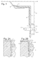
- FIG. 1 is a sectional view of a trough module arrangement of a motor vehicle with a trough module according to an embodiment
- FIG. 2A and FIG. 2B is a method according to an embodiment for manufacturing a trough module on FIG. 1 .
- FIG. 1 shows a sectional view of a trough module arrangement for a motor vehicle with a trough module according to an embodiment.
- the trough module exhibits a wall 1 that includes a plastic, in particular PP GF20, and defines a trough with a tank opening. Only a left upper portion of the trough is discernible in the sectional view on FIG. 1 .
- the wall 1 is secured to a body 4 of the motor vehicle, and sealed against the latter with a peripheral seal 5 .
- the trough can be sealed by a cover 8 , which can be locked with a bolt 2 .
- the bolt 2 passes through a passage opening 1 . 1 in the wall with an annular flange and a recess 8 . 1 in the cover 8 .
- the bolt 2 on FIG. 1 is shifted to the left for unlocking, as denoted there by a motion arrow, and to the right for locking.
- the bolt can also positively interact with another back cut, in particular a hook, in the cover 8 instead of the recess 8 . 1 .
- the passage opening 1 . 1 incorporates a seal 3 that is made out of a different plastic than the wall 1 , in particular out of TPE, and together with the peripheral seal 5 is molded, in particular injection molded, with the wall 1 by way of an overflow web 6 .
- the seal 3 is designed as an elastic or soft annular seal, and its inner edge tightly contacts the bolt 2 along its entire periphery, while also mounting or guiding the latter to enable its one-dimensional displacement (horizontal on FIG. 1 ).
- the inner edge is elastically expanded slightly by the bolt 2 passing through it.
- FIG. 2A and FIG. 2B show a method according to an embodiment for manufacturing the trough module on FIG. 1 .
- the wall 1 is injection molded by means of a multipart injection mold 7 . 1 , 7 . 2 .
- the injection molded part 7 . 2 is then replaced by the injection molded part 7 . 3 to create an annular cavity, an overflow channel communicating therewith, as well as another cavity communicating therewith on the peripheral edge of the wall 1 , in which the peripheral seal 5 and, by way of the overflow channel, the overflow web 6 and seal 3 are molded in a second shot depicted on FIG. 2B , joined with the wall 1 in the process.
- the seal 3 , peripheral seal 5 , peripheral web 6 and wall 1 are here materially bonded with each other. In a modification not shown, they can additionally or alternatively also be positively joined together, in particular by forming projections in the molding process that engage back cuts of the wall 1 from behind (not depicted).
- the bolt 2 exhibits a hooked side arm 2 . 1 , which is cut on FIG. 1 , extends on an exterior side of the wall facing away from the cover 8 (left on FIG. 1 ) and can be actuated (not depicted) on a side opposite the passage opening 1 . 1 (right on FIG. 1 ). In this way, an actuator, control cable or rod system can also be placed remotely from the bolt 2 .
Abstract
Description
Claims (9)
Applications Claiming Priority (3)
| Application Number | Priority Date | Filing Date | Title |
|---|---|---|---|
| DE102012023655.7 | 2012-11-28 | ||
| DE102012023655 | 2012-11-28 | ||
| DE102012023655.7A DE102012023655A1 (en) | 2012-11-28 | 2012-11-28 | Motor vehicle tray module with seal |
Publications (2)
| Publication Number | Publication Date |
|---|---|
| US20140183898A1 US20140183898A1 (en) | 2014-07-03 |
| US8926004B2 true US8926004B2 (en) | 2015-01-06 |
Family
ID=49818424
Family Applications (1)
| Application Number | Title | Priority Date | Filing Date |
|---|---|---|---|
| US14/090,363 Expired - Fee Related US8926004B2 (en) | 2012-11-28 | 2013-11-26 | Motor vehicle trough module with seal |
Country Status (4)
| Country | Link |
|---|---|
| US (1) | US8926004B2 (en) |
| CN (1) | CN103847813B (en) |
| DE (1) | DE102012023655A1 (en) |
| GB (1) | GB2510456A (en) |
Cited By (7)
| Publication number | Priority date | Publication date | Assignee | Title |
|---|---|---|---|---|
| US10065497B2 (en) | 2014-12-11 | 2018-09-04 | Kautex Textron Gmbh & Co. Kg | Filling system on a motor vehicle, having at least two storage tanks for liquid or gaseous operating materials |
| US10293668B1 (en) | 2017-12-12 | 2019-05-21 | Gm Global Technology Operations Llc. | Water management systems for vehicle sunroof assemblies |
| US11358647B1 (en) | 2021-01-12 | 2022-06-14 | GM Global Technology Operations LLC | Locally reinforced foam-filled composite components for vehicle body structures and methods of making the same |
| US11383771B1 (en) | 2021-04-09 | 2022-07-12 | GM Global Technology Operations LLC | Integrated fiber-reinforced polymer vehicle rail-and-panel structures and methods of making the same |
| US11420683B2 (en) | 2021-01-20 | 2022-08-23 | GM Global Technology Operations LLC | Fiber-reinforced polymer composite components for vehicle body structures and methods of making the same |
| US11541939B2 (en) | 2021-01-05 | 2023-01-03 | GM Global Technology Operations LLC | Laminate composite roof panels with internal localized structural reinforcements for motor vehicles |
| US11919276B2 (en) | 2021-01-05 | 2024-03-05 | GM Global Technology Operations LLC | Transparent composite body panels with localized structural reinforcements for motor vehicles |
Families Citing this family (2)
| Publication number | Priority date | Publication date | Assignee | Title |
|---|---|---|---|---|
| DE102020127323A1 (en) * | 2020-10-16 | 2022-04-21 | Bayerische Motoren Werke Aktiengesellschaft | Trough device for a motor vehicle, in particular for a motor vehicle |
| US11821242B2 (en) * | 2021-03-05 | 2023-11-21 | Ford Global Technologies, Llc | Fuel/charge port door assembly override systems and methods |
Citations (32)
| Publication number | Priority date | Publication date | Assignee | Title |
|---|---|---|---|---|
| DE1653956A1 (en) | 1967-05-13 | 1971-05-13 | Daimler Benz Ag | Locking device for a trunk lid and for a flap on a motor vehicle |
| US4525004A (en) | 1982-02-19 | 1985-06-25 | Nifco Inc. | Lid lock structure |
| US4718713A (en) * | 1985-06-06 | 1988-01-12 | Mazda Motor Corporation | Front structure of vehicle body |
| US4892351A (en) * | 1987-03-13 | 1990-01-09 | Honda Giken Kogyo K.K. | Water drain trough for automotive sunroof |
| US4938526A (en) * | 1986-12-04 | 1990-07-03 | Mazda Motor Corporation | Wiper mounting structure |
| US5120106A (en) * | 1990-02-27 | 1992-06-09 | Mazda Motor Corporation | Structure of a front body of a motor vehicle |
| DE4307454C1 (en) | 1993-03-10 | 1994-04-28 | Daimler Benz Ag | Fastener for hinged cover on vehicle - has swivel mounted, ring shaped adjustable damping block which fits around bolt locating housing and has various sizes of radial profiles |
| DE19612098A1 (en) | 1995-04-05 | 1996-10-10 | Volkswagen Ag | Latching arrangement for lid covering cavity in vehicle body |
| US6193305B1 (en) * | 1998-07-24 | 2001-02-27 | Honda Giken Kogyo Kabushiki Kaisha | Windshield supporting structure |
| US20020060475A1 (en) * | 2000-11-23 | 2002-05-23 | Kim Jong-Soo | Assemble structure of crash pad assembly and cowl panel assembly for vehicle |
| US20030178873A1 (en) * | 2002-03-20 | 2003-09-25 | Nissan Motor Co., Ltd. | Cowl structure for a vehicle |
| US20050134089A1 (en) * | 2003-12-22 | 2005-06-23 | Nissan Technical Center North America, Inc. | Vehicle cowl structure with vent pipe |
| US6923286B2 (en) * | 2002-02-26 | 2005-08-02 | Toyoda Gosei Co., Ltd. | Pedestrian protecting device |
| DE102004003073A1 (en) | 2004-01-21 | 2005-08-18 | Opel Eisenach Gmbh | Hinged flap for vehicle especially for fuel filler has a remote mounted servo motor linked to the flap by a flexible drive |
| US20050179285A1 (en) * | 2004-02-13 | 2005-08-18 | Nissan Motor Co., Ltd. | Vehicle cowl structure |
| US20060016814A1 (en) | 2004-07-20 | 2006-01-26 | Itw Automotive Products Gmbh & Co. Kg | Locking system for a fuel door housing |
| US7219953B2 (en) * | 2005-03-11 | 2007-05-22 | Nissan Technical Center North America, Inc. | Cowl cover with integrated washer fluid passageway |
| US20090146459A1 (en) * | 2007-12-07 | 2009-06-11 | Nissan Motor Co., Ltd. | Cowl structure of vehicle |
| US7552964B2 (en) * | 2007-03-02 | 2009-06-30 | Honda Motor Co., Ltd. | Front windshield support structure of a vehicle |
| US20100301055A1 (en) | 2009-05-26 | 2010-12-02 | Gm Global Technology Operations, Inc. | Tank flap module for a motor vehicle |
| US20110049933A1 (en) * | 2009-09-01 | 2011-03-03 | Nihon Plast Co., Ltd. | Cowl-top cover |
| US8002335B2 (en) * | 2008-04-18 | 2011-08-23 | Suzuki Motor Corporation | Vehicle cowl structure |
| US20120161462A1 (en) | 2009-09-02 | 2012-06-28 | GM Global Technology Operations LLC | Fuel tank cover module |
| US20130057027A1 (en) * | 2010-05-11 | 2013-03-07 | Nissan Motor Co., Ltd | Vehicle body structure |
| US20130181482A1 (en) * | 2012-01-16 | 2013-07-18 | Takahiro Suzaki | Body front structure of vehicle |
| US20130214560A1 (en) * | 2010-09-28 | 2013-08-22 | Honda Motor Co., Ltd. | Structure for positioning cowl top for vehicle |
| US20130221705A1 (en) * | 2011-08-31 | 2013-08-29 | Nishikawa Rubber Co., Ltd. | Body front structure for automobile |
| US20130300154A1 (en) * | 2012-05-08 | 2013-11-14 | GM Global Technology Operations LLC | Motor vehicle with water chamber |
| US20130320712A1 (en) * | 2011-02-24 | 2013-12-05 | Toyota Jidosha Kabushiki Kaisha | Cowl structure for an automobile |
| US20130341968A1 (en) * | 2011-12-03 | 2013-12-26 | GM Global Technology Operations LLC | Motor vehicle body |
| US8641130B2 (en) * | 2011-09-23 | 2014-02-04 | Nissan North America, Inc. | Vehicle cowl cover |
| US20140175835A1 (en) * | 2012-12-21 | 2014-06-26 | Mazda Motor Corporation | Front vehicle-body structure of vehicle |
-
2012
- 2012-11-28 DE DE102012023655.7A patent/DE102012023655A1/en not_active Withdrawn
-
2013
- 2013-11-11 GB GB1319860.1A patent/GB2510456A/en not_active Withdrawn
- 2013-11-26 US US14/090,363 patent/US8926004B2/en not_active Expired - Fee Related
- 2013-11-28 CN CN201310757468.0A patent/CN103847813B/en not_active Expired - Fee Related
Patent Citations (33)
| Publication number | Priority date | Publication date | Assignee | Title |
|---|---|---|---|---|
| DE1653956A1 (en) | 1967-05-13 | 1971-05-13 | Daimler Benz Ag | Locking device for a trunk lid and for a flap on a motor vehicle |
| US4525004A (en) | 1982-02-19 | 1985-06-25 | Nifco Inc. | Lid lock structure |
| US4718713A (en) * | 1985-06-06 | 1988-01-12 | Mazda Motor Corporation | Front structure of vehicle body |
| US4938526A (en) * | 1986-12-04 | 1990-07-03 | Mazda Motor Corporation | Wiper mounting structure |
| US4892351A (en) * | 1987-03-13 | 1990-01-09 | Honda Giken Kogyo K.K. | Water drain trough for automotive sunroof |
| US5120106A (en) * | 1990-02-27 | 1992-06-09 | Mazda Motor Corporation | Structure of a front body of a motor vehicle |
| DE4307454C1 (en) | 1993-03-10 | 1994-04-28 | Daimler Benz Ag | Fastener for hinged cover on vehicle - has swivel mounted, ring shaped adjustable damping block which fits around bolt locating housing and has various sizes of radial profiles |
| DE19612098A1 (en) | 1995-04-05 | 1996-10-10 | Volkswagen Ag | Latching arrangement for lid covering cavity in vehicle body |
| US6193305B1 (en) * | 1998-07-24 | 2001-02-27 | Honda Giken Kogyo Kabushiki Kaisha | Windshield supporting structure |
| US20020060475A1 (en) * | 2000-11-23 | 2002-05-23 | Kim Jong-Soo | Assemble structure of crash pad assembly and cowl panel assembly for vehicle |
| US6923286B2 (en) * | 2002-02-26 | 2005-08-02 | Toyoda Gosei Co., Ltd. | Pedestrian protecting device |
| US20030178873A1 (en) * | 2002-03-20 | 2003-09-25 | Nissan Motor Co., Ltd. | Cowl structure for a vehicle |
| US20050134089A1 (en) * | 2003-12-22 | 2005-06-23 | Nissan Technical Center North America, Inc. | Vehicle cowl structure with vent pipe |
| DE102004003073A1 (en) | 2004-01-21 | 2005-08-18 | Opel Eisenach Gmbh | Hinged flap for vehicle especially for fuel filler has a remote mounted servo motor linked to the flap by a flexible drive |
| US20050179285A1 (en) * | 2004-02-13 | 2005-08-18 | Nissan Motor Co., Ltd. | Vehicle cowl structure |
| US20060016814A1 (en) | 2004-07-20 | 2006-01-26 | Itw Automotive Products Gmbh & Co. Kg | Locking system for a fuel door housing |
| US7219953B2 (en) * | 2005-03-11 | 2007-05-22 | Nissan Technical Center North America, Inc. | Cowl cover with integrated washer fluid passageway |
| US7552964B2 (en) * | 2007-03-02 | 2009-06-30 | Honda Motor Co., Ltd. | Front windshield support structure of a vehicle |
| US20090146459A1 (en) * | 2007-12-07 | 2009-06-11 | Nissan Motor Co., Ltd. | Cowl structure of vehicle |
| US8002335B2 (en) * | 2008-04-18 | 2011-08-23 | Suzuki Motor Corporation | Vehicle cowl structure |
| US20100301055A1 (en) | 2009-05-26 | 2010-12-02 | Gm Global Technology Operations, Inc. | Tank flap module for a motor vehicle |
| US20110049933A1 (en) * | 2009-09-01 | 2011-03-03 | Nihon Plast Co., Ltd. | Cowl-top cover |
| US8474901B2 (en) * | 2009-09-01 | 2013-07-02 | Nihon Plast Co., Ltd. | Cowl-top cover |
| US20120161462A1 (en) | 2009-09-02 | 2012-06-28 | GM Global Technology Operations LLC | Fuel tank cover module |
| US20130057027A1 (en) * | 2010-05-11 | 2013-03-07 | Nissan Motor Co., Ltd | Vehicle body structure |
| US20130214560A1 (en) * | 2010-09-28 | 2013-08-22 | Honda Motor Co., Ltd. | Structure for positioning cowl top for vehicle |
| US20130320712A1 (en) * | 2011-02-24 | 2013-12-05 | Toyota Jidosha Kabushiki Kaisha | Cowl structure for an automobile |
| US20130221705A1 (en) * | 2011-08-31 | 2013-08-29 | Nishikawa Rubber Co., Ltd. | Body front structure for automobile |
| US8641130B2 (en) * | 2011-09-23 | 2014-02-04 | Nissan North America, Inc. | Vehicle cowl cover |
| US20130341968A1 (en) * | 2011-12-03 | 2013-12-26 | GM Global Technology Operations LLC | Motor vehicle body |
| US20130181482A1 (en) * | 2012-01-16 | 2013-07-18 | Takahiro Suzaki | Body front structure of vehicle |
| US20130300154A1 (en) * | 2012-05-08 | 2013-11-14 | GM Global Technology Operations LLC | Motor vehicle with water chamber |
| US20140175835A1 (en) * | 2012-12-21 | 2014-06-26 | Mazda Motor Corporation | Front vehicle-body structure of vehicle |
Non-Patent Citations (1)
| Title |
|---|
| German Patent Office, German Patent Search Report for Application No. 102012023655.7 mailed Sep. 10, 2013. |
Cited By (7)
| Publication number | Priority date | Publication date | Assignee | Title |
|---|---|---|---|---|
| US10065497B2 (en) | 2014-12-11 | 2018-09-04 | Kautex Textron Gmbh & Co. Kg | Filling system on a motor vehicle, having at least two storage tanks for liquid or gaseous operating materials |
| US10293668B1 (en) | 2017-12-12 | 2019-05-21 | Gm Global Technology Operations Llc. | Water management systems for vehicle sunroof assemblies |
| US11541939B2 (en) | 2021-01-05 | 2023-01-03 | GM Global Technology Operations LLC | Laminate composite roof panels with internal localized structural reinforcements for motor vehicles |
| US11919276B2 (en) | 2021-01-05 | 2024-03-05 | GM Global Technology Operations LLC | Transparent composite body panels with localized structural reinforcements for motor vehicles |
| US11358647B1 (en) | 2021-01-12 | 2022-06-14 | GM Global Technology Operations LLC | Locally reinforced foam-filled composite components for vehicle body structures and methods of making the same |
| US11420683B2 (en) | 2021-01-20 | 2022-08-23 | GM Global Technology Operations LLC | Fiber-reinforced polymer composite components for vehicle body structures and methods of making the same |
| US11383771B1 (en) | 2021-04-09 | 2022-07-12 | GM Global Technology Operations LLC | Integrated fiber-reinforced polymer vehicle rail-and-panel structures and methods of making the same |
Also Published As
| Publication number | Publication date |
|---|---|
| DE102012023655A1 (en) | 2014-05-28 |
| CN103847813A (en) | 2014-06-11 |
| US20140183898A1 (en) | 2014-07-03 |
| GB2510456A (en) | 2014-08-06 |
| GB201319860D0 (en) | 2013-12-25 |
| CN103847813B (en) | 2018-01-12 |
Similar Documents
| Publication | Publication Date | Title |
|---|---|---|
| US8926004B2 (en) | Motor vehicle trough module with seal | |
| US8556326B2 (en) | Fuel tank cover module | |
| US10059177B2 (en) | Structural component for motor vehicle part and motor vehicle part including the component | |
| CN105050846B (en) | Working liquid container | |
| US10100906B2 (en) | Spindle drive for an adjustment element of a motor vehicle | |
| EP3110648B1 (en) | Filler neck housing or charging housing | |
| US10220688B2 (en) | Inner box for a vehicle tailgate including a technical panel fitted thereto | |
| US8870217B2 (en) | Airbag housing for vehicle and manufacturing method thereof | |
| CN103328249A (en) | Tank recess | |
| US20140361555A1 (en) | Motor vehicle door lock | |
| US8360501B2 (en) | Tank flap module for a motor vehicle | |
| US9327656B2 (en) | Vehicle interior material | |
| US20170008206A1 (en) | Structural Molded Part, Motor Vehicle Fitting Element and Method for Producing a Structural Molded Part | |
| CN102529837B (en) | Multi-part moulding strip | |
| GB2520823A (en) | Front module of a motor vehicle | |
| CN204687808U (en) | A kind of tail-gate of self-propelled vehicle | |
| CN103806764B (en) | There is the vehicle latche system of collision bumper | |
| US8833836B2 (en) | Tunable water deflector | |
| US20150090713A1 (en) | Fuel filler door module | |
| US20110080013A1 (en) | Device for attachment of a bumper covering | |
| US20150130207A1 (en) | Storage compartment apparatus for door of a vehicle | |
| JP6100670B2 (en) | Automotive door trim | |
| CN102991320A (en) | Two-shot secondary seal | |
| JP5598768B2 (en) | Automotive interior parts | |
| US20220341453A1 (en) | Fastener with Integral Seal |
Legal Events
| Date | Code | Title | Description |
|---|---|---|---|
| FEPP | Fee payment procedure |
Free format text: PAYOR NUMBER ASSIGNED (ORIGINAL EVENT CODE: ASPN); ENTITY STATUS OF PATENT OWNER: LARGE ENTITY |
|
| AS | Assignment |
Owner name: GM GLOBAL TECHNOLOGY OPERATIONS LLC, MICHIGAN Free format text: ASSIGNMENT OF ASSIGNORS INTEREST;ASSIGNORS:BETZEN, HEIKO;FROMMANN, MARKUS;SIGNING DATES FROM 20140218 TO 20140219;REEL/FRAME:032483/0462 |
|
| AS | Assignment |
Owner name: WILMINGTON TRUST COMPANY, DELAWARE Free format text: SECURITY INTEREST;ASSIGNOR:GM GLOBAL TECHNOLOGY OPERATIONS LLC;REEL/FRAME:033135/0440 Effective date: 20101027 |
|
| AS | Assignment |
Owner name: GM GLOBAL TECHNOLOGY OPERATIONS LLC, MICHIGAN Free format text: RELEASE BY SECURED PARTY;ASSIGNOR:WILMINGTON TRUST COMPANY;REEL/FRAME:034189/0065 Effective date: 20141017 |
|
| STCF | Information on status: patent grant |
Free format text: PATENTED CASE |
|
| MAFP | Maintenance fee payment |
Free format text: PAYMENT OF MAINTENANCE FEE, 4TH YEAR, LARGE ENTITY (ORIGINAL EVENT CODE: M1551) Year of fee payment: 4 |
|
| FEPP | Fee payment procedure |
Free format text: MAINTENANCE FEE REMINDER MAILED (ORIGINAL EVENT CODE: REM.); ENTITY STATUS OF PATENT OWNER: LARGE ENTITY |
|
| LAPS | Lapse for failure to pay maintenance fees |
Free format text: PATENT EXPIRED FOR FAILURE TO PAY MAINTENANCE FEES (ORIGINAL EVENT CODE: EXP.); ENTITY STATUS OF PATENT OWNER: LARGE ENTITY |
|
| STCH | Information on status: patent discontinuation |
Free format text: PATENT EXPIRED DUE TO NONPAYMENT OF MAINTENANCE FEES UNDER 37 CFR 1.362 |
|
| FP | Lapsed due to failure to pay maintenance fee |
Effective date: 20230106 |