US8911403B2 - Syringe infusion pump - Google Patents
Syringe infusion pump Download PDFInfo
- Publication number
- US8911403B2 US8911403B2 US12/157,477 US15747708A US8911403B2 US 8911403 B2 US8911403 B2 US 8911403B2 US 15747708 A US15747708 A US 15747708A US 8911403 B2 US8911403 B2 US 8911403B2
- Authority
- US
- United States
- Prior art keywords
- barrel
- syringe
- plunger
- holder
- infusion pump
- Prior art date
- Legal status (The legal status is an assumption and is not a legal conclusion. Google has not performed a legal analysis and makes no representation as to the accuracy of the status listed.)
- Expired - Fee Related, expires
Links
Images


Classifications
-
- F—MECHANICAL ENGINEERING; LIGHTING; HEATING; WEAPONS; BLASTING
- F04—POSITIVE - DISPLACEMENT MACHINES FOR LIQUIDS; PUMPS FOR LIQUIDS OR ELASTIC FLUIDS
- F04B—POSITIVE-DISPLACEMENT MACHINES FOR LIQUIDS; PUMPS
- F04B9/00—Piston machines or pumps characterised by the driving or driven means to or from their working members
- F04B9/02—Piston machines or pumps characterised by the driving or driven means to or from their working members the means being mechanical
-
- A—HUMAN NECESSITIES
- A61—MEDICAL OR VETERINARY SCIENCE; HYGIENE
- A61M—DEVICES FOR INTRODUCING MEDIA INTO, OR ONTO, THE BODY; DEVICES FOR TRANSDUCING BODY MEDIA OR FOR TAKING MEDIA FROM THE BODY; DEVICES FOR PRODUCING OR ENDING SLEEP OR STUPOR
- A61M5/00—Devices for bringing media into the body in a subcutaneous, intra-vascular or intramuscular way; Accessories therefor, e.g. filling or cleaning devices, arm-rests
- A61M5/14—Infusion devices, e.g. infusing by gravity; Blood infusion; Accessories therefor
- A61M5/142—Pressure infusion, e.g. using pumps
- A61M5/145—Pressure infusion, e.g. using pumps using pressurised reservoirs, e.g. pressurised by means of pistons
- A61M5/1452—Pressure infusion, e.g. using pumps using pressurised reservoirs, e.g. pressurised by means of pistons pressurised by means of pistons
- A61M5/1456—Pressure infusion, e.g. using pumps using pressurised reservoirs, e.g. pressurised by means of pistons pressurised by means of pistons with a replaceable reservoir comprising a piston rod to be moved into the reservoir, e.g. the piston rod is part of the removable reservoir
-
- A—HUMAN NECESSITIES
- A61—MEDICAL OR VETERINARY SCIENCE; HYGIENE
- A61M—DEVICES FOR INTRODUCING MEDIA INTO, OR ONTO, THE BODY; DEVICES FOR TRANSDUCING BODY MEDIA OR FOR TAKING MEDIA FROM THE BODY; DEVICES FOR PRODUCING OR ENDING SLEEP OR STUPOR
- A61M5/00—Devices for bringing media into the body in a subcutaneous, intra-vascular or intramuscular way; Accessories therefor, e.g. filling or cleaning devices, arm-rests
- A61M5/14—Infusion devices, e.g. infusing by gravity; Blood infusion; Accessories therefor
- A61M5/168—Means for controlling media flow to the body or for metering media to the body, e.g. drip meters, counters ; Monitoring media flow to the body
- A61M5/16831—Monitoring, detecting, signalling or eliminating infusion flow anomalies
- A61M5/16854—Monitoring, detecting, signalling or eliminating infusion flow anomalies by monitoring line pressure
-
- A—HUMAN NECESSITIES
- A61—MEDICAL OR VETERINARY SCIENCE; HYGIENE
- A61M—DEVICES FOR INTRODUCING MEDIA INTO, OR ONTO, THE BODY; DEVICES FOR TRANSDUCING BODY MEDIA OR FOR TAKING MEDIA FROM THE BODY; DEVICES FOR PRODUCING OR ENDING SLEEP OR STUPOR
- A61M2205/00—General characteristics of the apparatus
- A61M2205/33—Controlling, regulating or measuring
- A61M2205/332—Force measuring means
-
- A—HUMAN NECESSITIES
- A61—MEDICAL OR VETERINARY SCIENCE; HYGIENE
- A61M—DEVICES FOR INTRODUCING MEDIA INTO, OR ONTO, THE BODY; DEVICES FOR TRANSDUCING BODY MEDIA OR FOR TAKING MEDIA FROM THE BODY; DEVICES FOR PRODUCING OR ENDING SLEEP OR STUPOR
- A61M2209/00—Ancillary equipment
- A61M2209/08—Supports for equipment
- A61M2209/082—Mounting brackets, arm supports for equipment
Definitions
- This patent application generally relates to infusion pumps. More particularly it relates to syringe infusion pumps. More particularly it relates to a drive mechanism for syringe infusion pumps.
- syringe infusion pumps accept a range of syringe sizes, typically from 1 cc to 60 cc or more in volume from a variety of syringe manufacturers.
- syringe infusion pumps accept a range of syringe sizes, typically from 1 cc to 60 cc or more in volume from a variety of syringe manufacturers.
- these devices use a motor under control of a microprocessor.
- a motor such as is available from Maxon Precision Motors, Inc., Fall River, Mass., can be used.
- the motor is connected to a lead screw which advances a pushing element that pushes against the plunger of the syringe, driving it into the barrel of the syringe, thus dispensing fluid or other material.
- the devices have used sensors for determining the size of syringe loaded, the position of the plunger within its travel, whether the plunger is captured by the pushing element, and the driving force needed to push the plunger.
- the devices have also included encoders or other means for determining the motor speed.
- the syringe drives have fixed the barrel of the syringe against a fixture, such as a V-block.
- a spring loaded clamp mechanism has been used to capture the barrel of the syringe against the V-block.
- the pushing element has not always pushed along the center line of the syringe, and the variance between pushing element and syringe center line can be as much as 1 inch or more.
- the variance in the syringe center line with respect to the pushing surface has caused difficulties in measuring the force applied to the syringe which is used to estimate fluid pressure within the syringe.
- a syringe infusion pump that includes a syringe, a syringe barrel holder, and a force sensor.
- the syringe includes a barrel and a plunger.
- the plunger has a plunger axis.
- the barrel has a barrel axis and a barrel diameter.
- the syringe is one of a plurality of syringes, each having a different barrel diameter.
- the syringe barrel holder provides the barrel axis automatically aligned with the force sensor for each syringe of the plurality of syringes.
- a syringe infusion pump that includes a syringe, a syringe plunger holder, and a force sensor.
- the syringe includes a barrel and a plunger.
- the plunger has a plunger axis and the barrel has a barrel diameter.
- the syringe is one of a plurality of syringes, each having a different barrel diameter.
- the syringe holder includes a plunger holder.
- the syringe plunger holder maintains a constant plunger axis independent of the barrel diameter.
- a syringe infusion pump that includes a syringe, a syringe plunger holder, and a force sensor.
- the syringe includes a barrel and a plunger.
- the plunger has a plunger axis.
- the barrel has a barrel axis and a barrel diameter.
- the syringe is one of a plurality of syringes, each having a different barrel diameter.
- the syringe plunger holder provides the plunger axis approximately aligned with the barrel axis independent of the barrel diameter.
- a syringe infusion pump that includes a syringe, a syringe barrel holder, and a force sensor.
- the syringe includes a barrel and a plunger.
- the barrel has a barrel axis and a barrel diameter.
- the syringe is one of a plurality of syringes, each having a different barrel diameter.
- the plurality of syringes includes a syringe having a smallest barrel diameter.
- the syringe barrel holder provides the barrel axis approximately aligned with the force sensor for a syringe having a barrel diameter that is less than or equal to two times the smallest barrel diameter.
- a syringe infusion pump comprising a syringe, a motor, a drive head, and a drive head position sensing mechanism.
- the motor is connected to move the drive head to facilitate operating the syringe.
- the drive head position sensing mechanism includes a guide rod, a pin, and a guide rod sensor.
- the guide rod has a helical groove.
- the pin extends from the drive head and fits in the helical groove.
- the guide rod rotates as the drive head moves, and the guide rod sensor senses rotation of the guide rod for use in determining drive head position.
- the method includes providing a syringe, wherein the syringe includes a barrel and a plunger.
- the plunger has a plunger axis.
- the barrel has a barrel axis and a barrel diameter.
- the syringe is one of a plurality of syringes, each having a different barrel diameter.
- the method also includes providing a syringe infusion pump that includes a syringe barrel holder and a force sensor.
- the barrel syringe holder provides the barrel axis automatically aligned with the force sensor for each syringe of the plurality of syringes.
- the method also includes using the syringe infusion pump to provide the fluid.
- FIG. 1 is a three dimensional view of one embodiment of a syringe infusion pump of the present patent application
- FIG. 2 is a three dimensional view of a drive head, motor, and position sensing mechanism of the syringe infusion pump of FIG. 1 ;
- FIGS. 3 a - 3 c are a three dimensional cutaway views of a portion of the drive head of FIG. 2 showing a plunger in position in front of a force sensor, and showing plunger clamp elements maintaining the plunger axis in front of the center of the force sensor;
- FIG. 4 is another three dimensional view of the drive head of FIG. 2 ;
- FIG. 5 is a block diagram of electronic components for the syringe infusion pump
- FIGS. 6 a - 6 d are three dimensional views of the barrel holder portion of the syringe holder of FIG. 1 showing how the axis of the barrel is maintained in the same position regardless of the diameter of the barrel;
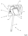
- FIG. 7 is another three dimensional view of the barrel holder portion of the syringe holder of FIGS. 6 a - 6 d.
- One embodiment of the present patent application provides a syringe infusion pump with a force sensor and a syringe holder.
- the syringe holder includes a syringe plunger holder and a syringe barrel holder.
- the syringe holder can include mechanisms that provide the syringe plunger axis and the syringe barrel axis automatically aligned with the force sensor for all sized syringes.
- Syringe infusion pump 20 includes drive head 22 , syringe barrel holder 24 , motor 26 , lead screw 28 , and position sensing device 30 , as shown in FIGS. 1 and 2 .
- Drive head 22 includes force sensor 32 against which plunger 36 of syringe 38 is positioned, as shown in FIGS. 3 a - 3 c .
- Force sensor 32 can be one available from Strain Measurement Devices, Meriden, Conn.
- Plunger 36 is held in position against force sensor 32 by syringe plunger holder and syringe plunger flange holder 40 that includes front plunger clamp element 42 a and rear plunger clamp element 42 b .
- Plunger clamp elements 42 a , 42 b have V-grooves 44 a , 44 b that both hold plunger 36 and capture plunger flange 46 .
- plunger axis 54 extends directly into center 56 of force sensor 32 , as shown in FIGS. 3 a - 3 c and FIG. 4 .
- Plunger clamp elements 42 a , 42 b are connected to gear 48 through racks 50 a , 50 b so that plunger clamp elements 42 a , 42 b are constrained to move equal distances in opposite directions to each other, maintaining plunger flange 46 centered before force sensor 32 and maintaining plunger axis 54 of plunger 36 extending directly into center 56 of force sensor 32 , regardless of the diameter of plunger 36 .
- Gear 48 , racks 50 a , 50 b are included in drive head housing 58 .
- One embodiment has a first plunger flange holder drive shaft that includes rack 50 a and a second plunger flange holder drive shaft that includes rack 50 b.
- Post 60 holds spring 62 for providing pressure for restoring plunger clamp elements 42 a , 42 b toward each other, as shown in FIG. 4 .
- Force sensor 32 senses the force being applied to plunger 36 by drive head 22 .
- Force sensor 32 is connected to motor processor 64 on electronic circuit board 66 .
- Motor 26 , barrel sensor 76 , and position sensor 78 are also connected to motor processor 64 on electronic circuit board 66 .
- Motor processor 64 can be one available from Microchip Technology Inc., Chandler, Ariz.
- Barrel sensor 76 and position sensor 78 can be ones available from US Digital, Inc., Vancouver, Wash.
- Electronic circuit board 66 also includes main microprocessor 68 .
- Keypad 70 , display 72 , and battery 74 are connected to main microprocessor 68 .
- Main processor 68 and display 72 can be ones available from Sharp Electronics Corporation, Romeoville, Ill.
- Motor processor 64 controls speed of motor 26 in a software closed control loop by monitoring two quadrature signals emitted by a motor encoder that is part of motor 26 .
- Motor processor 64 monitors output of force sensor 32 and provides an alarm signal to alarm 79 if a preset force above a threshold is detected. This force translates to a resultant fluid pressure based upon the cross sectional area of syringe barrel 96 .
- Motor processor 64 also monitors barrel sensor 76 and determines its outer diameter and thence its volume based upon a software look up table that cross references barrel diameter to syringe barrel volume.
- Motor processor 64 also monitors position sensor 78 and from this position determines the state of fill of syringe barrel 96 installed.
- Main processor 68 sends the display information to display 72 to be visually communicated to the user. Main processor 68 also monitors keypad 70 to enable the user to control the device via key press.
- Battery 74 supplies power to all the electronics and motor 26 .
- Position of drive head 22 along lead screw 28 is measured with position sensing device 30 , as shown in FIGS. 1 and 2 .
- Position sensing device 30 includes guide rod 80 and position sensor 78 .
- Guide rod 80 has helical groove 84 .
- Pin 86 extends from drive head 22 into helical groove 84 and causes guide rod 80 to rotate as drive head 22 moves under control of lead screw 28 and motor 26 . Because helical groove 84 extends only once around guide rod 80 , rotation of guide rod 80 can be used to accurately determine position of drive head 22 along lead screw 28 .
- Rotation of guide rod 80 is measured with position sensor 78 , and data from position sensor 78 is fed to motor processor 64 on circuit board 66 .
- position sensor 78 includes an absolute encoder for detecting angular movement of guide rod 80 .
- Syringe barrel holder 24 includes front barrel clamp element 90 a and rear barrel clamp element 90 b , as shown in FIGS. 6 a - 6 d .
- Front barrel clamp element 90 a has a curved portion 94 to hold syringe barrel 96 in position within groove 98 in rear barrel clamp element 90 b .
- Groove 98 of rear barrel clamp element 90 b may have different flat regions 100 a , 100 b to facilitate accommodating barrels having different diameters.
- Flat regions 100 c can be used to facilitate accommodating barrels having collars.
- Syringe barrel holder 24 also includes barrel flange clamp 102 on the side facing drive head 22 , as shown in FIGS. 6 a - 6 d and 7 .
- Barrel flange clamp 102 is for capturing barrel flange 104 in a fixed position, as shown in FIGS. 6 a - 6 d and FIG. 7 so that position of drive head 22 alone determines the amount of penetration of plunger into syringe barrel 96 .
- Syringe holder 106 includes syringe plunger holder and syringe plunger flange holder 40 and syringe barrel holder 24 .
- Syringe barrel holder 24 also includes barrel centering mechanism 108 for automatically centering barrel axis 110 of barrel 96 along plunger axis 54 and along center 56 of force sensor 32 .
- Barrel centering mechanism 108 provides that both front barrel clamp element 90 a and rear barrel clamp element 90 b move equal distances in opposite directions when syringe barrel 96 is inserted, maintaining barrel axis 110 in fixed position regardless of the size of barrel 96 , as shown in FIGS. 6 a - 6 d.
- Barrel centering mechanism 108 includes barrel racks 112 a , 112 b , as shown in FIGS. 6 a - 6 d .
- Barrel rack 112 a is connected to front barrel clamp element 90 a and to barrel clamp sensor gear 114 located in base 116 , as shown in FIG. 1 .
- Barrel rack 112 b is connected to rear barrel clamp element 90 b and to barrel clamp sensor gear 114 .
- Barrel sensor 76 is also connected to barrel clamp sensor gear 114 , and from the magnitude of rotation it measures of barrel clamp sensor gear 114 barrel sensor 76 determines the size of syringe barrel 96 .
- barrel sensor 76 includes an absolute encoder for detecting angular movement of barrel clamp sensor gear 114 .
- barrel sensor 76 includes an absolute encoder whose angular movement provides a measure of the movement of barrel rack 112 a , as shown in FIGS. 6 b - 6 d .
- One embodiment has a first barrel holder drive shaft that includes barrel rack 112 a and a second barrel holder drive shaft that includes barrel rack 112 b.
- Spring shaft 124 carries spring 126 that provides a force against base 116 pulling front barrel clamp element 90 a toward rear barrel clamp element 90 b to apply pressure to and hold syringe barrel 96 .
- Guide shaft 128 extends from front barrel clamp element 90 a through rear barrel clamp element 90 b and into base 116 .
Landscapes
- Health & Medical Sciences (AREA)
- Engineering & Computer Science (AREA)
- Animal Behavior & Ethology (AREA)
- General Health & Medical Sciences (AREA)
- Biomedical Technology (AREA)
- Heart & Thoracic Surgery (AREA)
- Hematology (AREA)
- Life Sciences & Earth Sciences (AREA)
- Vascular Medicine (AREA)
- Anesthesiology (AREA)
- Public Health (AREA)
- Veterinary Medicine (AREA)
- Mechanical Engineering (AREA)
- General Engineering & Computer Science (AREA)
- Infusion, Injection, And Reservoir Apparatuses (AREA)
- Reciprocating Pumps (AREA)
Priority Applications (2)
| Application Number | Priority Date | Filing Date | Title |
|---|---|---|---|
| US12/157,477 US8911403B2 (en) | 2007-06-11 | 2008-06-11 | Syringe infusion pump |
| US13/742,960 US20130129532A1 (en) | 2007-06-11 | 2013-01-16 | Syringe Infusion Pump |
Applications Claiming Priority (2)
| Application Number | Priority Date | Filing Date | Title |
|---|---|---|---|
| US93423607P | 2007-06-11 | 2007-06-11 | |
| US12/157,477 US8911403B2 (en) | 2007-06-11 | 2008-06-11 | Syringe infusion pump |
Related Child Applications (1)
| Application Number | Title | Priority Date | Filing Date |
|---|---|---|---|
| US13/742,960 Continuation US20130129532A1 (en) | 2007-06-11 | 2013-01-16 | Syringe Infusion Pump |
Publications (2)
| Publication Number | Publication Date |
|---|---|
| US20090005736A1 US20090005736A1 (en) | 2009-01-01 |
| US8911403B2 true US8911403B2 (en) | 2014-12-16 |
Family
ID=40130068
Family Applications (2)
| Application Number | Title | Priority Date | Filing Date |
|---|---|---|---|
| US12/157,477 Expired - Fee Related US8911403B2 (en) | 2007-06-11 | 2008-06-11 | Syringe infusion pump |
| US13/742,960 Abandoned US20130129532A1 (en) | 2007-06-11 | 2013-01-16 | Syringe Infusion Pump |
Family Applications After (1)
| Application Number | Title | Priority Date | Filing Date |
|---|---|---|---|
| US13/742,960 Abandoned US20130129532A1 (en) | 2007-06-11 | 2013-01-16 | Syringe Infusion Pump |
Country Status (9)
| Country | Link |
|---|---|
| US (2) | US8911403B2 (es) |
| EP (1) | EP2207580A1 (es) |
| AU (1) | AU2008262348A1 (es) |
| CA (1) | CA2690551A1 (es) |
| CO (1) | CO6290709A2 (es) |
| MX (1) | MX2009013562A (es) |
| NZ (1) | NZ582512A (es) |
| WO (1) | WO2008153985A1 (es) |
| ZA (1) | ZA201000180B (es) |
Cited By (13)
| Publication number | Priority date | Publication date | Assignee | Title |
|---|---|---|---|---|
| US20140188076A1 (en) * | 2011-12-21 | 2014-07-03 | Deka Products Limited Partnership | Syringe Pump, and Related Method and System |
| CN105833379A (zh) * | 2016-03-28 | 2016-08-10 | 刘晓燕 | 一种自动输液回收系统 |
| CN105833380A (zh) * | 2016-03-28 | 2016-08-10 | 王荣华 | 一种托腕按压自动输液系统 |
| CN105879143A (zh) * | 2016-03-28 | 2016-08-24 | 王爱玉 | 一种压瓶自动输液回收方法 |
| US9744300B2 (en) | 2011-12-21 | 2017-08-29 | Deka Products Limited Partnership | Syringe pump and related method |
| US10245374B2 (en) | 2011-12-21 | 2019-04-02 | Deka Products Limited Partnership | Syringe pump |
| US10391241B2 (en) | 2010-01-22 | 2019-08-27 | Deka Products Limited Partnership | Syringe pump having a pressure sensor assembly |
| US10722645B2 (en) | 2011-12-21 | 2020-07-28 | Deka Products Limited Partnership | Syringe pump, and related method and system |
| US11116895B2 (en) | 2017-02-10 | 2021-09-14 | Baxter International Inc. | Volume-based flow rate compensation technique for infusion therapy |
| US11217340B2 (en) | 2011-12-21 | 2022-01-04 | Deka Products Limited Partnership | Syringe pump having a pressure sensor assembly |
| US11660388B2 (en) | 2018-07-13 | 2023-05-30 | Zyno Medical, Llc | High precision syringe with removable pump unit |
| US11679205B2 (en) | 2018-07-13 | 2023-06-20 | Zyno Medical Llc | High precision syringe with removable pump unit |
| US11801342B2 (en) | 2017-07-19 | 2023-10-31 | Smiths Medical Asd, Inc. | Housing arrangements for infusion pumps |
Families Citing this family (8)
| Publication number | Priority date | Publication date | Assignee | Title |
|---|---|---|---|---|
| US7866617B2 (en) * | 2009-04-08 | 2011-01-11 | Baxter International Inc. | Slide and lock clamps |
| KR101203887B1 (ko) * | 2010-10-28 | 2012-11-23 | (주)디앤케이 | 피부 시술용 약물주입 장치 |
| SG11201503265QA (en) | 2012-12-07 | 2015-05-28 | Smiths Medical Asd Inc | Syringe characterization |
| EP3310411A4 (en) * | 2015-06-17 | 2019-01-23 | Smiths Medical ASD, Inc. | DEVICES, SYSTEMS AND METHOD FOR FORCE DETECTION FOR SYRINGE PUMPS |
| EP3576809B1 (en) | 2017-02-06 | 2023-05-10 | Sanofi-Aventis Deutschland GmbH | Assembly nest for a pen injection device with locking function |
| CN108295324A (zh) * | 2018-02-08 | 2018-07-20 | 钟春兰 | 一种多功能内科护理用气胸排气装置 |
| CN110215572B (zh) * | 2019-06-20 | 2021-07-23 | 纳智医疗设备(徐州)有限公司 | 一种注射泵用注射器定位机构 |
| CN112494325B (zh) * | 2020-11-19 | 2021-08-24 | 联赢医疗科技有限公司 | 一种可自动调配药液的输液机器人 |
Citations (9)
| Publication number | Priority date | Publication date | Assignee | Title |
|---|---|---|---|---|
| US5545140A (en) | 1991-05-23 | 1996-08-13 | Ivac Corporation | Syringe plunger driver |
| US5814015A (en) | 1995-02-24 | 1998-09-29 | Harvard Clinical Technology, Inc. | Infusion pump for at least one syringe |
| US20020016567A1 (en) * | 1998-04-10 | 2002-02-07 | Mark Hochman | Pressure/force computer controlled drug delivery system with exit pressure control |
| US20020077852A1 (en) * | 1992-10-15 | 2002-06-20 | The General Hospital, Massachusetts Corporation | Infusion pump with an electronically loadable drug library and a user interface for loading the library |
| US6415679B1 (en) | 2000-11-06 | 2002-07-09 | Chris D. Chiodo | Manual drive for positioning precision instruments |
| US6423035B1 (en) | 1999-06-18 | 2002-07-23 | Animas Corporation | Infusion pump with a sealed drive mechanism and improved method of occlusion detection |
| US20050177109A1 (en) * | 2004-02-06 | 2005-08-11 | Graziano Azzolini | Infusion pump for syringes |
| US20050217665A1 (en) * | 2004-03-30 | 2005-10-06 | Luconi Gregg F | Solar collector mounting array |
| US6992278B2 (en) | 2002-04-08 | 2006-01-31 | Gyros Ab | Homing process |
-
2008
- 2008-06-11 CA CA2690551A patent/CA2690551A1/en not_active Abandoned
- 2008-06-11 WO PCT/US2008/007193 patent/WO2008153985A1/en active Search and Examination
- 2008-06-11 MX MX2009013562A patent/MX2009013562A/es not_active Application Discontinuation
- 2008-06-11 EP EP08768263A patent/EP2207580A1/en not_active Withdrawn
- 2008-06-11 AU AU2008262348A patent/AU2008262348A1/en not_active Abandoned
- 2008-06-11 NZ NZ582512A patent/NZ582512A/xx not_active IP Right Cessation
- 2008-06-11 US US12/157,477 patent/US8911403B2/en not_active Expired - Fee Related
-
2010
- 2010-01-11 ZA ZA2010/00180A patent/ZA201000180B/en unknown
- 2010-01-12 CO CO10002348A patent/CO6290709A2/es active IP Right Grant
-
2013
- 2013-01-16 US US13/742,960 patent/US20130129532A1/en not_active Abandoned
Patent Citations (9)
| Publication number | Priority date | Publication date | Assignee | Title |
|---|---|---|---|---|
| US5545140A (en) | 1991-05-23 | 1996-08-13 | Ivac Corporation | Syringe plunger driver |
| US20020077852A1 (en) * | 1992-10-15 | 2002-06-20 | The General Hospital, Massachusetts Corporation | Infusion pump with an electronically loadable drug library and a user interface for loading the library |
| US5814015A (en) | 1995-02-24 | 1998-09-29 | Harvard Clinical Technology, Inc. | Infusion pump for at least one syringe |
| US20020016567A1 (en) * | 1998-04-10 | 2002-02-07 | Mark Hochman | Pressure/force computer controlled drug delivery system with exit pressure control |
| US6423035B1 (en) | 1999-06-18 | 2002-07-23 | Animas Corporation | Infusion pump with a sealed drive mechanism and improved method of occlusion detection |
| US6415679B1 (en) | 2000-11-06 | 2002-07-09 | Chris D. Chiodo | Manual drive for positioning precision instruments |
| US6992278B2 (en) | 2002-04-08 | 2006-01-31 | Gyros Ab | Homing process |
| US20050177109A1 (en) * | 2004-02-06 | 2005-08-11 | Graziano Azzolini | Infusion pump for syringes |
| US20050217665A1 (en) * | 2004-03-30 | 2005-10-06 | Luconi Gregg F | Solar collector mounting array |
Cited By (21)
| Publication number | Priority date | Publication date | Assignee | Title |
|---|---|---|---|---|
| US10391241B2 (en) | 2010-01-22 | 2019-08-27 | Deka Products Limited Partnership | Syringe pump having a pressure sensor assembly |
| US10561787B2 (en) | 2011-12-21 | 2020-02-18 | Deka Products Limited Partnership | Syringe pump and related method |
| US10722645B2 (en) | 2011-12-21 | 2020-07-28 | Deka Products Limited Partnership | Syringe pump, and related method and system |
| US11826543B2 (en) | 2011-12-21 | 2023-11-28 | Deka Products Limited Partneship | Syringe pump, and related method and system |
| US9744300B2 (en) | 2011-12-21 | 2017-08-29 | Deka Products Limited Partnership | Syringe pump and related method |
| US9789247B2 (en) * | 2011-12-21 | 2017-10-17 | Deka Products Limited Partnership | Syringe pump, and related method and system |
| US10245374B2 (en) | 2011-12-21 | 2019-04-02 | Deka Products Limited Partnership | Syringe pump |
| US11615886B2 (en) | 2011-12-21 | 2023-03-28 | Deka Products Limited Partnership | Syringe pump and related method |
| US11664106B2 (en) | 2011-12-21 | 2023-05-30 | Deka Products Limited Partnership | Syringe pump |
| US11217340B2 (en) | 2011-12-21 | 2022-01-04 | Deka Products Limited Partnership | Syringe pump having a pressure sensor assembly |
| US20140188076A1 (en) * | 2011-12-21 | 2014-07-03 | Deka Products Limited Partnership | Syringe Pump, and Related Method and System |
| US11129933B2 (en) | 2011-12-21 | 2021-09-28 | Deka Products Limited Partnership | Syringe pump, and related method and system |
| CN105879143B (zh) * | 2016-03-28 | 2021-11-09 | 王爱玉 | 一种压瓶自动输液回收方法 |
| CN105833379A (zh) * | 2016-03-28 | 2016-08-10 | 刘晓燕 | 一种自动输液回收系统 |
| CN105833380A (zh) * | 2016-03-28 | 2016-08-10 | 王荣华 | 一种托腕按压自动输液系统 |
| CN105879143A (zh) * | 2016-03-28 | 2016-08-24 | 王爱玉 | 一种压瓶自动输液回收方法 |
| US11116895B2 (en) | 2017-02-10 | 2021-09-14 | Baxter International Inc. | Volume-based flow rate compensation technique for infusion therapy |
| US11951282B2 (en) | 2017-02-10 | 2024-04-09 | Baxter International Inc. | Volume-based flow rate compensation technique for infusion therapy |
| US11801342B2 (en) | 2017-07-19 | 2023-10-31 | Smiths Medical Asd, Inc. | Housing arrangements for infusion pumps |
| US11679205B2 (en) | 2018-07-13 | 2023-06-20 | Zyno Medical Llc | High precision syringe with removable pump unit |
| US11660388B2 (en) | 2018-07-13 | 2023-05-30 | Zyno Medical, Llc | High precision syringe with removable pump unit |
Also Published As
| Publication number | Publication date |
|---|---|
| US20130129532A1 (en) | 2013-05-23 |
| WO2008153985A1 (en) | 2008-12-18 |
| CO6290709A2 (es) | 2011-06-20 |
| EP2207580A1 (en) | 2010-07-21 |
| CA2690551A1 (en) | 2008-12-18 |
| AU2008262348A1 (en) | 2008-12-18 |
| MX2009013562A (es) | 2010-08-31 |
| US20090005736A1 (en) | 2009-01-01 |
| ZA201000180B (en) | 2011-03-30 |
| NZ582512A (en) | 2012-11-30 |
Similar Documents
| Publication | Publication Date | Title |
|---|---|---|
| US8911403B2 (en) | Syringe infusion pump | |
| US8814830B2 (en) | Syringe plunger driver system | |
| US8713986B2 (en) | Electronic torque wrench calibration device and using method thereof | |
| JP2610385B2 (ja) | 注射器ポンプ | |
| JPH09506288A (ja) | シリンジプランジャーセンサーを有するシリンジ注入ポンプ | |
| US10589022B2 (en) | Syringe plunger positioning apparatus and method | |
| KR200493801Y1 (ko) | 플런저에 랙기어를 구비한 주사기 펌프 | |
| GB2076476A (en) | Peristaltic fluid-machines | |
| US7150791B2 (en) | Floating head liquid dispenser with dispensing head sensor | |
| EP1819381A1 (en) | Syringe driver monitoring means | |
| WO2018211746A1 (ja) | 輸液ポンプの点検機 | |
| AU2007203388B2 (en) | Syringe plunger driver system | |
| CN219579585U (zh) | 一种支持误触检测的注射泵 | |
| US20170281857A1 (en) | Syringe pump and drive head assembly therefor | |
| CN219398523U (zh) | 注射泵及注射装置 | |
| US20220008646A1 (en) | Liquid medicine administration device | |
| US11964127B2 (en) | External driving mechanism | |
| KR101725457B1 (ko) | 모니터링 기능을 갖는 개별제어 다축 실린지펌프 | |
| AU2019200809A1 (en) | Syringe pump and drive head assembly therefor | |
| CN116322831A (zh) | 注射泵中的输送保障 | |
| CN117398548A (zh) | 具有活塞制动器的注射泵 | |
| CN117490623A (zh) | 一种校准工装、校准方法及注射器余液检测方法 |
Legal Events
| Date | Code | Title | Description |
|---|---|---|---|
| AS | Assignment |
Owner name: NUMIA MEDICAL TECHNOLOGY, LLC, VERMONT Free format text: ASSIGNMENT OF ASSIGNORS INTEREST;ASSIGNORS:FLACHBART, ERIC JOHN;WARING, CAYLE E.;REEL/FRAME:021447/0655 Effective date: 20080811 |
|
| FEPP | Fee payment procedure |
Free format text: MAINTENANCE FEE REMINDER MAILED (ORIGINAL EVENT CODE: REM.) |
|
| LAPS | Lapse for failure to pay maintenance fees |
Free format text: PATENT EXPIRED FOR FAILURE TO PAY MAINTENANCE FEES (ORIGINAL EVENT CODE: EXP.); ENTITY STATUS OF PATENT OWNER: SMALL ENTITY |
|
| STCH | Information on status: patent discontinuation |
Free format text: PATENT EXPIRED DUE TO NONPAYMENT OF MAINTENANCE FEES UNDER 37 CFR 1.362 |
|
| FP | Lapsed due to failure to pay maintenance fee |
Effective date: 20181216 |