US8910757B2 - Heat-dissipating device for hydraulic brake system - Google Patents
Heat-dissipating device for hydraulic brake system Download PDFInfo
- Publication number
- US8910757B2 US8910757B2 US13/558,297 US201213558297A US8910757B2 US 8910757 B2 US8910757 B2 US 8910757B2 US 201213558297 A US201213558297 A US 201213558297A US 8910757 B2 US8910757 B2 US 8910757B2
- Authority
- US
- United States
- Prior art keywords
- heat
- dissipating
- tube
- brake system
- hydraulic brake
- Prior art date
- Legal status (The legal status is an assumption and is not a legal conclusion. Google has not performed a legal analysis and makes no representation as to the accuracy of the status listed.)
- Expired - Fee Related, expires
Links
- 230000007246 mechanism Effects 0.000 claims abstract description 25
- 230000000903 blocking effect Effects 0.000 claims description 10
- 230000000694 effects Effects 0.000 claims description 6
- 230000003247 decreasing effect Effects 0.000 claims description 2
- 230000000717 retained effect Effects 0.000 claims description 2
- 238000007789 sealing Methods 0.000 claims 1
- 239000007788 liquid Substances 0.000 description 5
- 241000309551 Arthraxon hispidus Species 0.000 description 3
- 230000015556 catabolic process Effects 0.000 description 1
- 230000000593 degrading effect Effects 0.000 description 1
- 230000017525 heat dissipation Effects 0.000 description 1
- 239000002184 metal Substances 0.000 description 1
- 239000007769 metal material Substances 0.000 description 1
- 230000004048 modification Effects 0.000 description 1
- 238000012986 modification Methods 0.000 description 1
- 229910052755 nonmetal Inorganic materials 0.000 description 1
Images


Classifications
-
- B—PERFORMING OPERATIONS; TRANSPORTING
- B62—LAND VEHICLES FOR TRAVELLING OTHERWISE THAN ON RAILS
- B62L—BRAKES SPECIALLY ADAPTED FOR CYCLES
- B62L3/00—Brake-actuating mechanisms; Arrangements thereof
- B62L3/02—Brake-actuating mechanisms; Arrangements thereof for control by a hand lever
- B62L3/023—Brake-actuating mechanisms; Arrangements thereof for control by a hand lever acting on fluid pressure systems
-
- B—PERFORMING OPERATIONS; TRANSPORTING
- B60—VEHICLES IN GENERAL
- B60T—VEHICLE BRAKE CONTROL SYSTEMS OR PARTS THEREOF; BRAKE CONTROL SYSTEMS OR PARTS THEREOF, IN GENERAL; ARRANGEMENT OF BRAKING ELEMENTS ON VEHICLES IN GENERAL; PORTABLE DEVICES FOR PREVENTING UNWANTED MOVEMENT OF VEHICLES; VEHICLE MODIFICATIONS TO FACILITATE COOLING OF BRAKES
- B60T5/00—Vehicle modifications to facilitate cooling of brakes
-
- F—MECHANICAL ENGINEERING; LIGHTING; HEATING; WEAPONS; BLASTING
- F16—ENGINEERING ELEMENTS AND UNITS; GENERAL MEASURES FOR PRODUCING AND MAINTAINING EFFECTIVE FUNCTIONING OF MACHINES OR INSTALLATIONS; THERMAL INSULATION IN GENERAL
- F16D—COUPLINGS FOR TRANSMITTING ROTATION; CLUTCHES; BRAKES
- F16D65/00—Parts or details
- F16D65/78—Features relating to cooling
- F16D2065/789—External cooling ribs
-
- F—MECHANICAL ENGINEERING; LIGHTING; HEATING; WEAPONS; BLASTING
- F16—ENGINEERING ELEMENTS AND UNITS; GENERAL MEASURES FOR PRODUCING AND MAINTAINING EFFECTIVE FUNCTIONING OF MACHINES OR INSTALLATIONS; THERMAL INSULATION IN GENERAL
- F16L—PIPES; JOINTS OR FITTINGS FOR PIPES; SUPPORTS FOR PIPES, CABLES OR PROTECTIVE TUBING; MEANS FOR THERMAL INSULATION IN GENERAL
- F16L11/00—Hoses, i.e. flexible pipes
- F16L11/04—Hoses, i.e. flexible pipes made of rubber or flexible plastics
- F16L11/12—Hoses, i.e. flexible pipes made of rubber or flexible plastics with arrangements for particular purposes, e.g. specially profiled, with protecting layer, heated, electrically conducting
Definitions
- the present invention relates to a heat-dissipating device, more particularly, to a heat-dissipating device for hydraulic brake system.
- a hydraulic brake system of a bicycle includes a brake mechanism, an oil hydraulic cylinder and an oil tube which is connected to a brake handlebar.
- the brake handlebar When the brake handlebar is pressed, the liquid in the oil tube is forced to flow to the oil hydraulic cylinder and the brake mechanism, and the brake mechanism is pressed by the hydraulic force to contact the wheel so as to make a brake.
- the friction resulted from the contact of the brake mechanism and the wheel can generate lot of heat to lead to a high temperature of the brake mechanism. If the temperature of the brake mechanism is unexpectedly high, the brake effect of the brake mechanism is poor, and the brake mechanism is worse in structural strength and mechanical properties, thus resulting in risks of riding.
- a heat-dissipating element is disposed between an oil tube and an oil hydraulic cylinder, the heat-dissipating element is formed with plural fins to increase heat-dissipating surface area, so as to help brake mechanism to rapidly dissipate the heat.
- the oil tube and a heat-dissipating element are screwed together via a tube fixedly disposed at the distal end of the oil tube.
- the liquid can possible leak from the joint portion of the oil tube and the heat-dissipating element.
- the assembly of the tube and the oil tube not only is inconvenient in production but also can cause a limitation to the length of the oil tube.
- the heat-dissipating element cannot sufficiently dissipate the heat.
- the liquid from the brake mechanism flows back into the oil tube, and since the oil tube is usually of non-metal material so that its heat-dissipating efficiency is poor, the heat of the liquid in the oil tube is hard to be dissipated outside. Therefore, the high-temperature liquid flows into the brake mechanism in a next brake, thus degrading the brake performance of the brake mechanism.
- the present invention is, therefore, arisen to obviate or at least mitigate the above mentioned disadvantages.
- the main object of the present invention is to provide a heat-dissipating device for hydraulic brake system which has larger heat-dissipating surface area so as to promote the performance of heat-dissipation and is flexibly adjustable.
- a heat-dissipating device for hydraulic brake system of the present invention includes a heat-dissipating element, a sleeve element and a plurality of heat-dissipating tube units.
- the heat-dissipating element is hollow and has a fixation end and a connecting end corresponding to each other, wherein the fixation end is connected to and communicated with a hydraulic cylinder or a brake mechanism, the connecting end is received in an oil tube so that the heat-dissipating element and the oil tube are tightly connected and communicated with each other.
- the heat-dissipating element has a heat-dissipating portion disposed between the fixation end and the connecting end.
- the sleeve element is sleeved around the joint portion of the heat-dissipating element and the oil tube and disposed at the connecting end of the heat-dissipating element.
- the sleeve element can strengthen the combination of the heat-dissipating element and the oil tube and improve leakage-proof effect.
- the heat-dissipating tube units are sleeved around the oil tube and sequentially connected, and one of the heat-dissipating tube units abuts against the sleeve element.
- the heat-dissipating device for hydraulic brake system may further includes a adjusting element, wherein the adjusting element is disposed at one end of the oil tube away from the heat-dissipating element, the heat-dissipating tube units which are sequentially connected abut against and between the sleeve element and the adjusting element and are thereby positioned, and the adjusting element is adjustable in length so as to abut against the heat-dissipating tube units and be thereby positioned.
- the heat-dissipating device for hydraulic brake system of the present invention can significantly improve the heat-dissipating efficiencies of the hydraulic cylinder and the oil tube, is easy to adjust and mount, and is suitable for various types of bicycles.
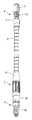
- FIG. 1 is a perspective view of the present invention
- FIG. 2 is a cross-sectional view of the present invention
- FIG. 3 is a perspective breakdown drawing of the present invention
- FIG. 3A is a partial close-up view FIG. 3 ;
- FIG. 3B is a partial close-up view according to a second embodiment of the present invention.
- FIG. 4 is a drawing showing a heat-dissipating device for hydraulic brake system in use according to the present invention
- FIG. 5A is a partial perspective view according to a third embodiment of the present invention.
- FIG. 5B is a partial cross-sectional view according to the third embodiment of the present invention.
- FIG. 6A is a partial perspective view according to a fourth embodiment of the present invention.
- FIG. 6B is a partial cross-sectional view according to the fourth embodiment of the present invention.
- FIG. 7A is a partial perspective view according to a fifth embodiment of the present invention.
- FIG. 7B is a partial cross-sectional view according to the fifth embodiment of the present invention.
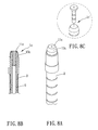
- FIG. 8A is a partial perspective view according to a sixth embodiment of the present invention.
- FIG. 8B is a partial cross-sectional view according to the sixth embodiment of the present invention.
- FIG. 8C is a partial perspective view according to a seventh embodiment of the present invention.
- a heat-dissipating device for hydraulic brake system of the present invention includes a heat-dissipating element 1 , a sleeve element 2 and a plurality of heat-dissipating tube unit 3 .
- the heat-dissipating device can be adapted to be mounted between a brake oil tube 5 and a brake mechanism 7 .
- the heat-dissipating element 1 is hollow and has a fixation end 11 and a connecting end 12 corresponding to each other.
- the fixation end 11 is adapted for being connected to and communicated with the brake mechanism 7 or a hydraulic cylinder
- the connecting end 12 is adapted for being connected to the oil tube 5 so that the heat-dissipating element 1 and the oil tube 5 are tightly connected and communicated with each other.
- the heat-dissipating element 1 further includes a heat-dissipating portion 13 disposed between the fixation end 11 and the connecting end 12 .
- the heat-dissipating portion 13 is formed with a plurality of heat-dissipating fins, and the heat-dissipating fins project radially outward from the heat-dissipating element 1 and are arranged alternatively.
- the heat-dissipating element 1 is made of metal, and the heat-dissipating fins are preferably arranged in the same plane and in fish-bone shape.
- a radial extent of each of the heat-dissipating fin is greater than an extent of the spacing of each two adjacent heat-dissipating fins, so as to significantly increase heat-dissipating surface area.
- the connecting end 12 has a threaded section whose outer diameter is not greater than the inner diameter of the oil tube 5 .
- An outer surface of the threaded section is formed with a thread (as shown in FIG. 3A ), plural annular cams (the connecting end 12 b as shown in FIG. 3B ) or the like for being connected to the oil tube 5 .
- the heat-dissipating element 1 further includes an outer thread located between the heat-dissipating portion 13 and the threaded section.
- An annular recess which faces away from the fixation end and is centered about the threaded section is formed between the threaded section and the outer thread.
- the sleeve element 2 is sleeved around the joint portion of the heat-dissipating element 1 and the oil tube 5 and disposed at the connecting end 12 of the heat-dissipating element 1 , and the sleeve element 2 can strengthen the combination of the heat-dissipating element 1 and the oil tube 5 and improve leakage-proof effect.
- the sleeve element 2 has a first end and a second end, an inner surface of the first end of the sleeve element 2 is formed with an inner thread for being connected to the outer thread of the heat-dissipating element 1 , an inner surface of second end of the sleeve element 2 is formed with a necked section having a smaller inner diameter, so that a space is formed between the necked section and the annular recess of the heat-dissipating element 1 .
- the heat-dissipating device for hydraulic brake system further includes an elastic washer 14 which is sleeved around the oil tube 5 and retained between the sleeve element 2 and the oil tube 5 . That is, the washer 14 is located in the space between the necked section and the annular recess so as to avoid the leakage.
- the heat-dissipating tube units 3 are sleeved around the oil tube 5 and sequentially connected, and one of the heat-dissipating tube units 3 abuts against the sleeve element.
- the heat-dissipating tube units 3 include cooperative engaging mechanisms, so that the heat-dissipating tube units 3 can be sequentially connected and conduct the heat from the heat-dissipating element 1 and dissipate the heat outside.
- a heat-dissipating device for hydraulic brake system further includes a adjusting element 4 which is disposed at the remote end (away from the heat-dissipating element 1 ) of the oil tube 5 .
- the heat-dissipating tube units 3 which are sequentially connected abut against and between the sleeve element 2 and the adjusting element 4 and are thereby positioned.
- the adjusting element 4 is adjustable in length so as to abut against the heat-dissipating tube units 3 and be thereby positioned.
- the adjusting element 4 includes an external tube 41 , an internal tube 42 and an elastic element 43 .
- An inner surface of the external tube 41 is formed with an inner threaded section 411
- an outer surface of the internal tube 42 is formed with an outer threaded section 421 .
- the inner surface of the external tube 41 is formed further with a first blocking portion 412 protruding inwardly
- the outer surface of the internal tube 42 is formed further with a second blocking portion 422 protruding outwardly.
- the inner threaded section 411 of the external tube and the outer threaded section 421 of the internal tube are screwed together, the second blocking portion 422 is located in the external tube 41 , and the elastic element 43 abuts against and between the first blocking portion 412 and the second blocking portion 422 .
- the length of the adjusting element 4 can be changed via screwing the external tube 41 , such that the adjusting element 4 can abut against the heat-dissipating tube units 3 .
- the heat-dissipating element 1 is connected to an oil hydraulic cylinder or the brake mechanism 7 via its fixation end 11 , and the remote end of the oil tube 5 away from the heat-dissipating element 1 is adapted for receiving a joint head 6 having a threaded portion 62 .
- An end of the joint head 6 may have a thread 61 for being connected to a brake handlebar 8 .
- a washer 63 may be disposed between the joint portion of the oil tube 5 and the joint head 6 and the adjusting element 4 so as to improve the leakage-proof effect.
- an outer surface of a sleeve element 2 a is formed with at least one groove 21 so as to increase heat-dissipating surface area.
- a heat-dissipating element 1 a includes a fixation end 11 a , a connecting end 12 a and a heat-dissipating portion 13 a .
- a sleeve element 2 b may be directly sleeved around the joint portion of the heat-dissipating element 1 a and the oil tube 5 and is then fixedly positioned via pressing without thread and washer, and this can also result in a firm fixation of the sleeve element 2 b and an excellent leakage-proof effect.
- a heat-dissipating element 1 b includes a smooth recessed heat-dissipating portion 13 b .
- a heat-dissipating element 1 c of a preferable embodiment as shown in FIGS. 8A and 8B according to the present invention the structure of the heat-dissipating element 1 c is much simplified.
- the heat-dissipating element 1 c has a smaller fixation end 11 c and a smaller heat-dissipating portion 13 c in size.
- Heat-dissipating element may be composed of two parts, such as a heat-dissipating element 1 c ′ as shown in FIG. 8C .
- the heat-dissipating device for hydraulic brake system of the present invention has a simple and flexibly-assembled structure, can provide function of leakage-proofing, has larger heat-dissipating surface area, can provide protection for the oil tube, and is flexibly adjustable.
Landscapes
- Engineering & Computer Science (AREA)
- Mechanical Engineering (AREA)
- Physics & Mathematics (AREA)
- Fluid Mechanics (AREA)
- Transportation (AREA)
- Valves And Accessory Devices For Braking Systems (AREA)
- Braking Arrangements (AREA)
Abstract
A heat-dissipating device for hydraulic brake system is provided. The device includes a heat-dissipating element and a plurality of heat-dissipating tube units. The heat-dissipating element has a heat-dissipating portion which has large surface area, and is located between a brake mechanism and an oil tube. The heat-dissipating tube units are sleeved around the oil tube in order. Thereby, the heat generated by the brake mechanism can be dissipated rapidly by the heat-dissipating element and the heat-dissipating tube units, so as to promote performance of the brake mechanism.
Description
1. Field of the Invention
The present invention relates to a heat-dissipating device, more particularly, to a heat-dissipating device for hydraulic brake system.
2. Description of the Prior Art
Generally speaking, a hydraulic brake system of a bicycle includes a brake mechanism, an oil hydraulic cylinder and an oil tube which is connected to a brake handlebar. When the brake handlebar is pressed, the liquid in the oil tube is forced to flow to the oil hydraulic cylinder and the brake mechanism, and the brake mechanism is pressed by the hydraulic force to contact the wheel so as to make a brake.
However, the friction resulted from the contact of the brake mechanism and the wheel can generate lot of heat to lead to a high temperature of the brake mechanism. If the temperature of the brake mechanism is unexpectedly high, the brake effect of the brake mechanism is poor, and the brake mechanism is worse in structural strength and mechanical properties, thus resulting in risks of riding.
Therefore, to improve brake performance and riding safety, it is very important to rapidly dissipate the heat from the brake mechanism so as to lower the temperature of the brake mechanism. In a conventional heat-dissipating mechanism as disclosed in TW TWM284806, a heat-dissipating element is disposed between an oil tube and an oil hydraulic cylinder, the heat-dissipating element is formed with plural fins to increase heat-dissipating surface area, so as to help brake mechanism to rapidly dissipate the heat. In the above conventional heat-dissipating mechanism, the oil tube and a heat-dissipating element are screwed together via a tube fixedly disposed at the distal end of the oil tube. Hence, the liquid can possible leak from the joint portion of the oil tube and the heat-dissipating element. Additionally, the assembly of the tube and the oil tube not only is inconvenient in production but also can cause a limitation to the length of the oil tube. As such, since the assembly of the tube and the oil tube is completed, it is hard to be changed. More importantly, the heat-dissipating element cannot sufficiently dissipate the heat. The liquid from the brake mechanism flows back into the oil tube, and since the oil tube is usually of non-metal material so that its heat-dissipating efficiency is poor, the heat of the liquid in the oil tube is hard to be dissipated outside. Therefore, the high-temperature liquid flows into the brake mechanism in a next brake, thus degrading the brake performance of the brake mechanism.
The present invention is, therefore, arisen to obviate or at least mitigate the above mentioned disadvantages.
The main object of the present invention is to provide a heat-dissipating device for hydraulic brake system which has larger heat-dissipating surface area so as to promote the performance of heat-dissipation and is flexibly adjustable.
To achieve the above and other objects, a heat-dissipating device for hydraulic brake system of the present invention includes a heat-dissipating element, a sleeve element and a plurality of heat-dissipating tube units.
The heat-dissipating element is hollow and has a fixation end and a connecting end corresponding to each other, wherein the fixation end is connected to and communicated with a hydraulic cylinder or a brake mechanism, the connecting end is received in an oil tube so that the heat-dissipating element and the oil tube are tightly connected and communicated with each other. The heat-dissipating element has a heat-dissipating portion disposed between the fixation end and the connecting end.
The sleeve element is sleeved around the joint portion of the heat-dissipating element and the oil tube and disposed at the connecting end of the heat-dissipating element. The sleeve element can strengthen the combination of the heat-dissipating element and the oil tube and improve leakage-proof effect.
The heat-dissipating tube units are sleeved around the oil tube and sequentially connected, and one of the heat-dissipating tube units abuts against the sleeve element.
The heat-dissipating device for hydraulic brake system may further includes a adjusting element, wherein the adjusting element is disposed at one end of the oil tube away from the heat-dissipating element, the heat-dissipating tube units which are sequentially connected abut against and between the sleeve element and the adjusting element and are thereby positioned, and the adjusting element is adjustable in length so as to abut against the heat-dissipating tube units and be thereby positioned.
Whereby, the heat-dissipating device for hydraulic brake system of the present invention can significantly improve the heat-dissipating efficiencies of the hydraulic cylinder and the oil tube, is easy to adjust and mount, and is suitable for various types of bicycles.
The present invention will become more obvious from the following description when taken in connection with the accompanying drawings, which show, for purpose of illustrations only, the preferred embodiment(s) in accordance with the present invention.
As shown in FIGS. 1 to 4 , a heat-dissipating device for hydraulic brake system of the present invention includes a heat-dissipating element 1, a sleeve element 2 and a plurality of heat-dissipating tube unit 3. The heat-dissipating device can be adapted to be mounted between a brake oil tube 5 and a brake mechanism 7.
The heat-dissipating element 1 is hollow and has a fixation end 11 and a connecting end 12 corresponding to each other. The fixation end 11 is adapted for being connected to and communicated with the brake mechanism 7 or a hydraulic cylinder, and the connecting end 12 is adapted for being connected to the oil tube 5 so that the heat-dissipating element 1 and the oil tube 5 are tightly connected and communicated with each other. The heat-dissipating element 1 further includes a heat-dissipating portion 13 disposed between the fixation end 11 and the connecting end 12. Preferably, the heat-dissipating portion 13 is formed with a plurality of heat-dissipating fins, and the heat-dissipating fins project radially outward from the heat-dissipating element 1 and are arranged alternatively. More specifically, the heat-dissipating element 1 is made of metal, and the heat-dissipating fins are preferably arranged in the same plane and in fish-bone shape. A radial extent of each of the heat-dissipating fin is greater than an extent of the spacing of each two adjacent heat-dissipating fins, so as to significantly increase heat-dissipating surface area. The lengths of the heat-dissipating fins from the fixation end 11 to the connecting end 12 are gradually decreased. The connecting end 12 has a threaded section whose outer diameter is not greater than the inner diameter of the oil tube 5. An outer surface of the threaded section is formed with a thread (as shown in FIG. 3A ), plural annular cams (the connecting end 12 b as shown in FIG. 3B ) or the like for being connected to the oil tube 5. The heat-dissipating element 1 further includes an outer thread located between the heat-dissipating portion 13 and the threaded section. An annular recess which faces away from the fixation end and is centered about the threaded section is formed between the threaded section and the outer thread.
The sleeve element 2 is sleeved around the joint portion of the heat-dissipating element 1 and the oil tube 5 and disposed at the connecting end 12 of the heat-dissipating element 1, and the sleeve element 2 can strengthen the combination of the heat-dissipating element 1 and the oil tube 5 and improve leakage-proof effect. Preferably, the sleeve element 2 has a first end and a second end, an inner surface of the first end of the sleeve element 2 is formed with an inner thread for being connected to the outer thread of the heat-dissipating element 1, an inner surface of second end of the sleeve element 2 is formed with a necked section having a smaller inner diameter, so that a space is formed between the necked section and the annular recess of the heat-dissipating element 1. The heat-dissipating device for hydraulic brake system further includes an elastic washer 14 which is sleeved around the oil tube 5 and retained between the sleeve element 2 and the oil tube 5. That is, the washer 14 is located in the space between the necked section and the annular recess so as to avoid the leakage.
The heat-dissipating tube units 3 are sleeved around the oil tube 5 and sequentially connected, and one of the heat-dissipating tube units 3 abuts against the sleeve element. Preferably, the heat-dissipating tube units 3 include cooperative engaging mechanisms, so that the heat-dissipating tube units 3 can be sequentially connected and conduct the heat from the heat-dissipating element 1 and dissipate the heat outside.
In a preferable embodiment according to the present invention, a heat-dissipating device for hydraulic brake system further includes a adjusting element 4 which is disposed at the remote end (away from the heat-dissipating element 1) of the oil tube 5. The heat-dissipating tube units 3 which are sequentially connected abut against and between the sleeve element 2 and the adjusting element 4 and are thereby positioned. The adjusting element 4 is adjustable in length so as to abut against the heat-dissipating tube units 3 and be thereby positioned. Preferably, the adjusting element 4 includes an external tube 41, an internal tube 42 and an elastic element 43. An inner surface of the external tube 41 is formed with an inner threaded section 411, and an outer surface of the internal tube 42 is formed with an outer threaded section 421. The inner surface of the external tube 41 is formed further with a first blocking portion 412 protruding inwardly, and the outer surface of the internal tube 42 is formed further with a second blocking portion 422 protruding outwardly. The inner threaded section 411 of the external tube and the outer threaded section 421 of the internal tube are screwed together, the second blocking portion 422 is located in the external tube 41, and the elastic element 43 abuts against and between the first blocking portion 412 and the second blocking portion 422. The length of the adjusting element 4 can be changed via screwing the external tube 41, such that the adjusting element 4 can abut against the heat-dissipating tube units 3.
In actual use, the heat-dissipating element 1 is connected to an oil hydraulic cylinder or the brake mechanism 7 via its fixation end 11, and the remote end of the oil tube 5 away from the heat-dissipating element 1 is adapted for receiving a joint head 6 having a threaded portion 62. An end of the joint head 6 may have a thread 61 for being connected to a brake handlebar 8. Preferably, a washer 63 may be disposed between the joint portion of the oil tube 5 and the joint head 6 and the adjusting element 4 so as to improve the leakage-proof effect.
In a preferable embodiment as shown in FIGS. 5A and 5B according to the present invention, an outer surface of a sleeve element 2 a is formed with at least one groove 21 so as to increase heat-dissipating surface area.
In a preferable embodiment as shown in FIGS. 6A and 6B according to the present invention, a heat-dissipating element 1 a includes a fixation end 11 a, a connecting end 12 a and a heat-dissipating portion 13 a. A sleeve element 2 b may be directly sleeved around the joint portion of the heat-dissipating element 1 a and the oil tube 5 and is then fixedly positioned via pressing without thread and washer, and this can also result in a firm fixation of the sleeve element 2 b and an excellent leakage-proof effect.
In a preferable embodiment as shown in FIGS. 7A and 7B according to the present invention, a heat-dissipating element 1 b includes a smooth recessed heat-dissipating portion 13 b. In a heat-dissipating element 1 c of a preferable embodiment as shown in FIGS. 8A and 8B according to the present invention, the structure of the heat-dissipating element 1 c is much simplified. The heat-dissipating element 1 c has a smaller fixation end 11 c and a smaller heat-dissipating portion 13 c in size. Heat-dissipating element may be composed of two parts, such as a heat-dissipating element 1 c′ as shown in FIG. 8C .
Given the above, the heat-dissipating device for hydraulic brake system of the present invention has a simple and flexibly-assembled structure, can provide function of leakage-proofing, has larger heat-dissipating surface area, can provide protection for the oil tube, and is flexibly adjustable.
Although particular embodiments of the invention have been described in detail for purposes of illustration, various modifications and enhancements may be made without departing from the spirit and scope of the invention. Accordingly, the invention is not to be limited except as by the appended claims.
Claims (13)
1. A heat-dissipating device for hydraulic brake system, including:
a heat-dissipating element, being hollow and having a fixation end and a connecting end corresponding to each other, the fixation end being connected to and communicated with a brake mechanism, the connecting end being received in an oil tube so that the heat-dissipating element and the oil tube are tightly connected and communicated with each other via the connecting end, and the heat-dissipating element having a heat-dissipating portion disposed between the fixation end and the connecting end;
a sleeve element, sleeved around a joint portion of the heat-dissipating element and the oil tube and disposed at the connecting end of the heat-dissipating element, and the sleeve element serving to strengthen the combination of the heat-dissipating element and the oil tube and improve leakage-proof effect; and
a plurality of heat-dissipating tube units, sleeved around the oil tube and sequentially connected, and one of the heat-dissipating tube units abutting against the sleeve element;
wherein the connecting end is coaxially received in the oil tube;
wherein the connecting end, the oil tube and the sleeve element are coaxially arranged and radially overlapped;
wherein the heat-dissipating tube units are detachably sequentially connected.
2. The heat-dissipating device for hydraulic brake system of claim 1 , wherein the heat-dissipating portion includes a plurality of heat-dissipating fins, and the heat-dissipating fins project radially from the heat-dissipating element and are arranged alternatively.
3. The heat-dissipating device for hydraulic brake system of claim 2 , wherein the lengths of the heat-dissipating fins from the fixation end to the connecting end are decreased.
4. The heat-dissipating device for hydraulic brake system of claim 1 , further including a washer, wherein the washer is sleeved around the oil tube and retained between the sleeve element and the oil tube, and the washer is radially abutted at least between an inner surface of the heat-dissipating element and an outer surface of the oil tube.
5. The heat-dissipating device for hydraulic brake system of claim 1 , wherein an outer surface of the sleeve element is formed with at least one groove to increase heat-dissipating surface area.
6. The heat-dissipating device for hydraulic brake system of claim 1 , wherein an outer surface of the connecting end of the heat-dissipating element is formed with an outer thread, an inner surface of one end of the sleeve element is formed with an inner thread, and the outer thread of the heat-dissipating element and the inner thread of the sleeve element are screwed together.
7. The heat-dissipating device for hydraulic brake system of claim 1 , wherein the sleeve element is fixedly disposed around the oil tube and the heat-dissipating element via pressing, such that the sleeve element, the oil tube and the heat-dissipating element are positioned and in a gas-sealing relationship.
8. The heat-dissipating device for hydraulic brake system of claim 1 , further including a adjusting element, wherein the adjusting element is disposed at one end of the oil tube away from the heat-dissipating element, the heat-dissipating tube units which are sequentially connected abut against and between the sleeve element and the adjusting element and are thereby positioned, and the adjusting element is adjustable in length so as to abut against the heat-dissipating tube units and be thereby positioned.
9. The heat-dissipating device for hydraulic brake system of claim 8 , wherein the adjusting element includes an external tube, an internal tube and an elastic element, an inner surface of the external tube is formed with an inner threaded section, an outer surface of the internal tube is formed with an outer threaded section, the inner surface of the external tube is formed with a first blocking portion protruding inwardly, the outer surface of the internal tube is formed with a second blocking portion protruding outwardly, the inner threaded section of the external tube and the outer threaded section of the internal tube are screwed together, the second blocking portion is located in the external tube, and the elastic element abuts against and between the first blocking portion and the second blocking portion.
10. The heat-dissipating device for hydraulic brake system of claim 4 , wherein the washer includes two opposing conically tapered ends.
11. The heat-dissipating device for hydraulic brake system of claim 4 , wherein the heat-dissipating element further includes an annular wall coaxially disposed around the connecting end, an annular slot is formed between the annular wall and the connecting end, and the washer is partially received in the annular slot.
12. The heat-dissipating device for hydraulic brake system of claim 10 , wherein the heat-dissipating element further includes an annular wall coaxially disposed around the connecting end, an annular slot is formed between the annular wall and the connecting end, and the washer is partially received in the annular slot.
13. The heat-dissipating device for hydraulic brake system of claim 10 , wherein the sleeve element further includes a conically tapered inner surface, and one of the conically tapered ends is sealingly abutted against the conically tapered inner surface.
Priority Applications (1)
| Application Number | Priority Date | Filing Date | Title |
|---|---|---|---|
| US13/558,297 US8910757B2 (en) | 2012-07-25 | 2012-07-25 | Heat-dissipating device for hydraulic brake system |
Applications Claiming Priority (1)
| Application Number | Priority Date | Filing Date | Title |
|---|---|---|---|
| US13/558,297 US8910757B2 (en) | 2012-07-25 | 2012-07-25 | Heat-dissipating device for hydraulic brake system |
Publications (2)
| Publication Number | Publication Date |
|---|---|
| US20140027215A1 US20140027215A1 (en) | 2014-01-30 |
| US8910757B2 true US8910757B2 (en) | 2014-12-16 |
Family
ID=49993785
Family Applications (1)
| Application Number | Title | Priority Date | Filing Date |
|---|---|---|---|
| US13/558,297 Expired - Fee Related US8910757B2 (en) | 2012-07-25 | 2012-07-25 | Heat-dissipating device for hydraulic brake system |
Country Status (1)
| Country | Link |
|---|---|
| US (1) | US8910757B2 (en) |
Cited By (1)
| Publication number | Priority date | Publication date | Assignee | Title |
|---|---|---|---|---|
| US10407043B2 (en) | 2015-01-12 | 2019-09-10 | Sram, Llc | Hydraulic bicycle system |
Families Citing this family (2)
| Publication number | Priority date | Publication date | Assignee | Title |
|---|---|---|---|---|
| CA186469S (en) * | 2018-09-10 | 2020-05-19 | Australian Plumbing Products Pty Ltd | Flexible water hose |
| CN118030662B (en) * | 2024-03-28 | 2024-10-29 | 启东市远华机械有限公司 | Heat dissipation structure of a hydraulic pump station |
Citations (51)
| Publication number | Priority date | Publication date | Assignee | Title |
|---|---|---|---|---|
| US2063742A (en) * | 1934-04-07 | 1936-12-08 | Gen Motors Corp | Combined metal plate oil filter and oil cooler |
| US2486124A (en) * | 1946-02-02 | 1949-10-25 | Thomas E Crockett | Air compressor valve device |
| US3294148A (en) * | 1966-12-27 | Fuel feeding system for internal combustion engines | ||
| US3411746A (en) * | 1966-06-30 | 1968-11-19 | Balon Corp | Welded ball valve construction |
| US3699847A (en) * | 1971-02-04 | 1972-10-24 | Mc Donnell Douglas Corp | Cooled hydraulic system |
| US3720227A (en) * | 1970-06-01 | 1973-03-13 | Foxboro Co | Valve bonnet cooling system |
| US3776333A (en) * | 1971-09-09 | 1973-12-04 | W Mathauser | Bicycle brake arrangement |
| US3924619A (en) * | 1971-11-12 | 1975-12-09 | Taylor Diving & Salvage Co | Closed circuit, free-flow, underwater breathing system |
| US3993174A (en) * | 1973-12-06 | 1976-11-23 | Lynn A. Williams Engineering Company | Hydraulic bicycle brake system |
| US4036333A (en) * | 1976-02-13 | 1977-07-19 | Mathauser William R | Bicycle brake shoe with heat dissipating means |
| US4142577A (en) * | 1977-03-10 | 1979-03-06 | Erwin Klein | Cooling device for a liquid-cooled semiconductor power component |
| US4175648A (en) * | 1977-10-20 | 1979-11-27 | Sandor Sule | Device for the braking of bicycles |
| US4405160A (en) * | 1980-07-24 | 1983-09-20 | Toyota Jidosha Kogyo Kabushiki Kaisha | Hose joint with cooling fins |
| US4441592A (en) * | 1982-08-27 | 1984-04-10 | Kool-Stop International Inc. | Bicycle brake assembly |
| US4491095A (en) * | 1983-07-20 | 1985-01-01 | Avalon Research | Cyclic dwell engine |
| US4589380A (en) * | 1983-07-20 | 1986-05-20 | Avalon Research | Cyclic dwell engine |
| US4840348A (en) * | 1985-06-06 | 1989-06-20 | Usui Kokusai Sangyo Kabushiki Kaisha | Valve actuator for slide exhaust brake systems |
| US4874193A (en) * | 1975-04-09 | 1989-10-17 | Raychem Corporation | Heat-recoverable composition coupling device |
| US4887487A (en) * | 1988-05-03 | 1989-12-19 | Charles D. Johnson | Hydro-planetary power division system |
| US4921081A (en) * | 1988-12-22 | 1990-05-01 | Autra-Bike Co., Inc. | Hydraulic brake apparatus for bicycles |
| US4967780A (en) * | 1988-05-14 | 1990-11-06 | Mic Co., Ltd. | Anti-freezing device |
| US4979366A (en) * | 1983-11-28 | 1990-12-25 | Automotive Products Plc | Method of providing modular prefilled hydraulic control apparatus |
| US4991627A (en) * | 1986-08-25 | 1991-02-12 | Automotive Products Plc | Connector for modular prefilled hydraulic control apparatus |
| US5180353A (en) * | 1991-02-07 | 1993-01-19 | Csa, Inc. | Hydraulic resistive apparatus for exercise equipment |
| US5363739A (en) * | 1993-10-12 | 1994-11-15 | Graco Inc. | Reduced icing low friction air valve |
| US5701853A (en) * | 1995-02-07 | 1997-12-30 | Honda Giken Kogyo Kabushiki Kaisha | Oil cooling structure for a vehicle |
| US5813501A (en) * | 1996-10-18 | 1998-09-29 | Terry, Sr.; Maurice C. | Hand operated hydraulic vehicle brake |
| US5975118A (en) * | 1997-10-24 | 1999-11-02 | Johnson Controls Technology | Adapter for mounting an actuator to a valve |
| US6041898A (en) * | 1994-09-26 | 2000-03-28 | Maeda; Hiroyuki | Method of and device for cooling brake fluid |
| US6170617B1 (en) * | 1998-07-08 | 2001-01-09 | Shimano Inc. | Method of cooling bicycle disc brake |
| US6186559B1 (en) * | 1999-12-22 | 2001-02-13 | Visteon Global Technologies, Inc. | Tube coupling assembly |
| US6196358B1 (en) * | 1998-07-08 | 2001-03-06 | Shimano Inc. | Detachable fluid cooling system for bicycle disc brake |
| US6202802B1 (en) * | 1998-07-06 | 2001-03-20 | Shimano Inc. | Fluid cooled disc brake for bicycle |
| US6311710B1 (en) * | 1994-11-28 | 2001-11-06 | Powermass Corporation | Reduction of heat transfer between a body and its environment |
| US6427970B1 (en) * | 2001-03-16 | 2002-08-06 | Young & Franklin, Inc. | Heat dissipating voice coil activated valves |
| US20030010585A1 (en) * | 2001-07-16 | 2003-01-16 | Shimano, Inc. | Braking member and method of manufacturing same |
| US6591896B1 (en) * | 2002-05-23 | 2003-07-15 | Dennis Hansen | Method and system for providing a transmission fluid heat exchanger in-line with respect to an engine cooling system |
| US20030221726A1 (en) * | 2002-05-30 | 2003-12-04 | Roberto Semeia | First stage pressure reducing valve having a tubular plug, particularly for regulators of scuba breathing apparatus |
| US20040118831A1 (en) * | 2002-08-07 | 2004-06-24 | Phoenix Consultants, Ltd | Temperature regulated clothing |
| US6761574B1 (en) * | 1997-10-27 | 2004-07-13 | Halliburton Energy Services, Inc. | Coiled tubing connector |
| US6997284B1 (en) * | 2001-06-26 | 2006-02-14 | Spicer Technology, Inc. | Lubricant cooling system for a motor vehicle axle |
| US20080289326A1 (en) * | 1999-10-18 | 2008-11-27 | Ryota Ohashi | Pump Unit |
| US7614485B2 (en) * | 2003-02-08 | 2009-11-10 | Audi Ag | Disk brake comprising a cooling member |
| US20100276008A1 (en) * | 2009-01-29 | 2010-11-04 | Abrams Joseph H | Fluid Conduit Safety System With Separable Coupling |
| US20100288481A1 (en) * | 2006-01-19 | 2010-11-18 | Werner Zobel | Flat tube, flat tube heat exchanger, and method of manufacturing same |
| US20120222927A1 (en) * | 2011-03-03 | 2012-09-06 | John Marking | Cooler for a suspension damper |
| US8261537B2 (en) * | 2008-03-28 | 2012-09-11 | MAGNETI MARELLI S.p.A. | Mounting device for an injector in an exhaust system of an internal combustion engine |
| US8365878B2 (en) * | 2008-02-07 | 2013-02-05 | Shimano Inc. | Hydraulic disc brake caliper with one way plumbing |
| US8394241B2 (en) * | 2010-08-16 | 2013-03-12 | Shanghai Ariba Electric Co., Ltd. | Distillation-type drinking fountain and energy-saving heating unit thereof |
| US8464848B2 (en) * | 2011-01-29 | 2013-06-18 | Yuan-Hung WEN | Heat dissipation plate |
| US8500150B2 (en) * | 2010-05-13 | 2013-08-06 | Samsung Sdi Co., Ltd. | Transport apparatus |
-
2012
- 2012-07-25 US US13/558,297 patent/US8910757B2/en not_active Expired - Fee Related
Patent Citations (54)
| Publication number | Priority date | Publication date | Assignee | Title |
|---|---|---|---|---|
| US3294148A (en) * | 1966-12-27 | Fuel feeding system for internal combustion engines | ||
| US2063742A (en) * | 1934-04-07 | 1936-12-08 | Gen Motors Corp | Combined metal plate oil filter and oil cooler |
| US2486124A (en) * | 1946-02-02 | 1949-10-25 | Thomas E Crockett | Air compressor valve device |
| US3411746A (en) * | 1966-06-30 | 1968-11-19 | Balon Corp | Welded ball valve construction |
| US3720227A (en) * | 1970-06-01 | 1973-03-13 | Foxboro Co | Valve bonnet cooling system |
| US3699847A (en) * | 1971-02-04 | 1972-10-24 | Mc Donnell Douglas Corp | Cooled hydraulic system |
| US3776333A (en) * | 1971-09-09 | 1973-12-04 | W Mathauser | Bicycle brake arrangement |
| US3924619A (en) * | 1971-11-12 | 1975-12-09 | Taylor Diving & Salvage Co | Closed circuit, free-flow, underwater breathing system |
| US3993174A (en) * | 1973-12-06 | 1976-11-23 | Lynn A. Williams Engineering Company | Hydraulic bicycle brake system |
| US4874193A (en) * | 1975-04-09 | 1989-10-17 | Raychem Corporation | Heat-recoverable composition coupling device |
| US4036333A (en) * | 1976-02-13 | 1977-07-19 | Mathauser William R | Bicycle brake shoe with heat dissipating means |
| US4142577A (en) * | 1977-03-10 | 1979-03-06 | Erwin Klein | Cooling device for a liquid-cooled semiconductor power component |
| US4175648A (en) * | 1977-10-20 | 1979-11-27 | Sandor Sule | Device for the braking of bicycles |
| US4405160A (en) * | 1980-07-24 | 1983-09-20 | Toyota Jidosha Kogyo Kabushiki Kaisha | Hose joint with cooling fins |
| US4441592A (en) * | 1982-08-27 | 1984-04-10 | Kool-Stop International Inc. | Bicycle brake assembly |
| US4491095A (en) * | 1983-07-20 | 1985-01-01 | Avalon Research | Cyclic dwell engine |
| US4589380A (en) * | 1983-07-20 | 1986-05-20 | Avalon Research | Cyclic dwell engine |
| US4979366A (en) * | 1983-11-28 | 1990-12-25 | Automotive Products Plc | Method of providing modular prefilled hydraulic control apparatus |
| US4840348A (en) * | 1985-06-06 | 1989-06-20 | Usui Kokusai Sangyo Kabushiki Kaisha | Valve actuator for slide exhaust brake systems |
| US4991627A (en) * | 1986-08-25 | 1991-02-12 | Automotive Products Plc | Connector for modular prefilled hydraulic control apparatus |
| US4887487A (en) * | 1988-05-03 | 1989-12-19 | Charles D. Johnson | Hydro-planetary power division system |
| US4967780A (en) * | 1988-05-14 | 1990-11-06 | Mic Co., Ltd. | Anti-freezing device |
| US4921081A (en) * | 1988-12-22 | 1990-05-01 | Autra-Bike Co., Inc. | Hydraulic brake apparatus for bicycles |
| US5180353A (en) * | 1991-02-07 | 1993-01-19 | Csa, Inc. | Hydraulic resistive apparatus for exercise equipment |
| US5363739A (en) * | 1993-10-12 | 1994-11-15 | Graco Inc. | Reduced icing low friction air valve |
| US6041898A (en) * | 1994-09-26 | 2000-03-28 | Maeda; Hiroyuki | Method of and device for cooling brake fluid |
| US6311710B1 (en) * | 1994-11-28 | 2001-11-06 | Powermass Corporation | Reduction of heat transfer between a body and its environment |
| US5701853A (en) * | 1995-02-07 | 1997-12-30 | Honda Giken Kogyo Kabushiki Kaisha | Oil cooling structure for a vehicle |
| US5813501A (en) * | 1996-10-18 | 1998-09-29 | Terry, Sr.; Maurice C. | Hand operated hydraulic vehicle brake |
| US5975118A (en) * | 1997-10-24 | 1999-11-02 | Johnson Controls Technology | Adapter for mounting an actuator to a valve |
| US6761574B1 (en) * | 1997-10-27 | 2004-07-13 | Halliburton Energy Services, Inc. | Coiled tubing connector |
| US6321879B2 (en) * | 1998-07-06 | 2001-11-27 | Shimano Inc. | Fluid cooled disc brake for bicycle |
| US6202802B1 (en) * | 1998-07-06 | 2001-03-20 | Shimano Inc. | Fluid cooled disc brake for bicycle |
| US20010009213A1 (en) * | 1998-07-06 | 2001-07-26 | Yasushi Nakamura | Fluid cooled disc brake for bicycle |
| US6321880B2 (en) * | 1998-07-08 | 2001-11-27 | Shimano Inc. | Detachable fluid cooling system for bicycle disc brake |
| US6196358B1 (en) * | 1998-07-08 | 2001-03-06 | Shimano Inc. | Detachable fluid cooling system for bicycle disc brake |
| US6170617B1 (en) * | 1998-07-08 | 2001-01-09 | Shimano Inc. | Method of cooling bicycle disc brake |
| US20080289326A1 (en) * | 1999-10-18 | 2008-11-27 | Ryota Ohashi | Pump Unit |
| US6186559B1 (en) * | 1999-12-22 | 2001-02-13 | Visteon Global Technologies, Inc. | Tube coupling assembly |
| US6427970B1 (en) * | 2001-03-16 | 2002-08-06 | Young & Franklin, Inc. | Heat dissipating voice coil activated valves |
| US6997284B1 (en) * | 2001-06-26 | 2006-02-14 | Spicer Technology, Inc. | Lubricant cooling system for a motor vehicle axle |
| US20030010585A1 (en) * | 2001-07-16 | 2003-01-16 | Shimano, Inc. | Braking member and method of manufacturing same |
| US6591896B1 (en) * | 2002-05-23 | 2003-07-15 | Dennis Hansen | Method and system for providing a transmission fluid heat exchanger in-line with respect to an engine cooling system |
| US20030221726A1 (en) * | 2002-05-30 | 2003-12-04 | Roberto Semeia | First stage pressure reducing valve having a tubular plug, particularly for regulators of scuba breathing apparatus |
| US20040118831A1 (en) * | 2002-08-07 | 2004-06-24 | Phoenix Consultants, Ltd | Temperature regulated clothing |
| US7614485B2 (en) * | 2003-02-08 | 2009-11-10 | Audi Ag | Disk brake comprising a cooling member |
| US20100288481A1 (en) * | 2006-01-19 | 2010-11-18 | Werner Zobel | Flat tube, flat tube heat exchanger, and method of manufacturing same |
| US8365878B2 (en) * | 2008-02-07 | 2013-02-05 | Shimano Inc. | Hydraulic disc brake caliper with one way plumbing |
| US8261537B2 (en) * | 2008-03-28 | 2012-09-11 | MAGNETI MARELLI S.p.A. | Mounting device for an injector in an exhaust system of an internal combustion engine |
| US20100276008A1 (en) * | 2009-01-29 | 2010-11-04 | Abrams Joseph H | Fluid Conduit Safety System With Separable Coupling |
| US8500150B2 (en) * | 2010-05-13 | 2013-08-06 | Samsung Sdi Co., Ltd. | Transport apparatus |
| US8394241B2 (en) * | 2010-08-16 | 2013-03-12 | Shanghai Ariba Electric Co., Ltd. | Distillation-type drinking fountain and energy-saving heating unit thereof |
| US8464848B2 (en) * | 2011-01-29 | 2013-06-18 | Yuan-Hung WEN | Heat dissipation plate |
| US20120222927A1 (en) * | 2011-03-03 | 2012-09-06 | John Marking | Cooler for a suspension damper |
Cited By (1)
| Publication number | Priority date | Publication date | Assignee | Title |
|---|---|---|---|---|
| US10407043B2 (en) | 2015-01-12 | 2019-09-10 | Sram, Llc | Hydraulic bicycle system |
Also Published As
| Publication number | Publication date |
|---|---|
| US20140027215A1 (en) | 2014-01-30 |
Similar Documents
| Publication | Publication Date | Title |
|---|---|---|
| US8910757B2 (en) | Heat-dissipating device for hydraulic brake system | |
| US20110051430A1 (en) | Assembly structure for led fixture | |
| US20160130885A1 (en) | Connection structure between pipe body and steel joint of aluminum alloy drill pipe | |
| US20120118536A1 (en) | Radial heat sink with heat pipe set therein | |
| US10036213B2 (en) | Connection structure between pipe body and joint of aluminum alloy drill pipe | |
| JP2017082891A5 (en) | ||
| EP2687766A2 (en) | Heat-dissipating device for hydraulic brake system | |
| US20170097195A1 (en) | Knockdown heat dissipation unit | |
| TWM460952U (en) | Nut with cooling function | |
| CN106931122B (en) | Double-nut cooling type ball screw | |
| CN202229142U (en) | Radiator of LED (Light-emitting Diode) Lamp | |
| TWM445544U (en) | Heat-dissipating device for hydraulic brake system | |
| CN202329322U (en) | Combination structure of heat pipe and radiator | |
| CN103899860B (en) | A kind of damping connecting tube | |
| CN207599188U (en) | Connecting pipe fast assembling-disassembling presss from both sides and fluid line connecting structure | |
| TWI580922B (en) | One-time forming of the heat pipe seat | |
| CN203364078U (en) | Heat dissipating LED lamp | |
| WO2015086616A3 (en) | Piston-cylinder unit | |
| CN201141486Y (en) | Oil pipe joint device of bicycle brake caliper | |
| US20150308749A1 (en) | Combination fin and heat pipe assembly | |
| JP6622498B2 (en) | Fluid pressure cylinder | |
| US20160348702A1 (en) | Device configured for preloading bearing interfaces coupling concentrically arranged tubes | |
| CN203427976U (en) | Bicycle disc brake cable structure | |
| CN203962647U (en) | locking device | |
| TWM544464U (en) | Oil pipe connection structure |
Legal Events
| Date | Code | Title | Description |
|---|---|---|---|
| FEPP | Fee payment procedure |
Free format text: MAINTENANCE FEE REMINDER MAILED (ORIGINAL EVENT CODE: REM.) |
|
| LAPS | Lapse for failure to pay maintenance fees |
Free format text: PATENT EXPIRED FOR FAILURE TO PAY MAINTENANCE FEES (ORIGINAL EVENT CODE: EXP.); ENTITY STATUS OF PATENT OWNER: SMALL ENTITY |
|
| STCH | Information on status: patent discontinuation |
Free format text: PATENT EXPIRED DUE TO NONPAYMENT OF MAINTENANCE FEES UNDER 37 CFR 1.362 |
|
| FP | Lapsed due to failure to pay maintenance fee |
Effective date: 20181216 |