US8908177B2 - Correction of second-order diffraction effects in fiber-optic-based spectrometers - Google Patents
Correction of second-order diffraction effects in fiber-optic-based spectrometers Download PDFInfo
- Publication number
- US8908177B2 US8908177B2 US13/743,038 US201313743038A US8908177B2 US 8908177 B2 US8908177 B2 US 8908177B2 US 201313743038 A US201313743038 A US 201313743038A US 8908177 B2 US8908177 B2 US 8908177B2
- Authority
- US
- United States
- Prior art keywords
- order light
- spectrometer
- output
- relationship
- order
- Prior art date
- Legal status (The legal status is an assumption and is not a legal conclusion. Google has not performed a legal analysis and makes no representation as to the accuracy of the status listed.)
- Active
Links
- 230000000694 effects Effects 0.000 title description 2
- 238000000034 method Methods 0.000 claims description 56
- 238000005286 illumination Methods 0.000 claims description 25
- 230000008878 coupling Effects 0.000 claims description 3
- 238000010168 coupling process Methods 0.000 claims description 3
- 238000005859 coupling reaction Methods 0.000 claims description 3
- 229910052736 halogen Inorganic materials 0.000 description 9
- 230000003287 optical effect Effects 0.000 description 6
- XUIMIQQOPSSXEZ-UHFFFAOYSA-N Silicon Chemical compound [Si] XUIMIQQOPSSXEZ-UHFFFAOYSA-N 0.000 description 3
- 229910052710 silicon Inorganic materials 0.000 description 3
- 239000010703 silicon Substances 0.000 description 3
- 230000007423 decrease Effects 0.000 description 2
- 238000010586 diagram Methods 0.000 description 2
- 238000012545 processing Methods 0.000 description 2
- 230000004044 response Effects 0.000 description 2
- 230000008901 benefit Effects 0.000 description 1
- 230000000903 blocking effect Effects 0.000 description 1
- 239000000470 constituent Substances 0.000 description 1
- 230000008676 import Effects 0.000 description 1
- 238000010348 incorporation Methods 0.000 description 1
- 238000004519 manufacturing process Methods 0.000 description 1
- 238000005259 measurement Methods 0.000 description 1
- 239000000203 mixture Substances 0.000 description 1
- 238000012986 modification Methods 0.000 description 1
- 230000004048 modification Effects 0.000 description 1
- 238000012544 monitoring process Methods 0.000 description 1
- 230000008569 process Effects 0.000 description 1
- 239000000047 product Substances 0.000 description 1
- 230000004043 responsiveness Effects 0.000 description 1
- 230000035945 sensitivity Effects 0.000 description 1
- 238000001228 spectrum Methods 0.000 description 1
- 239000013589 supplement Substances 0.000 description 1
Images


Classifications
-
- G—PHYSICS
- G01—MEASURING; TESTING
- G01J—MEASUREMENT OF INTENSITY, VELOCITY, SPECTRAL CONTENT, POLARISATION, PHASE OR PULSE CHARACTERISTICS OF INFRARED, VISIBLE OR ULTRAVIOLET LIGHT; COLORIMETRY; RADIATION PYROMETRY
- G01J3/00—Spectrometry; Spectrophotometry; Monochromators; Measuring colours
- G01J3/02—Details
- G01J3/10—Arrangements of light sources specially adapted for spectrometry or colorimetry
-
- G—PHYSICS
- G01—MEASURING; TESTING
- G01J—MEASUREMENT OF INTENSITY, VELOCITY, SPECTRAL CONTENT, POLARISATION, PHASE OR PULSE CHARACTERISTICS OF INFRARED, VISIBLE OR ULTRAVIOLET LIGHT; COLORIMETRY; RADIATION PYROMETRY
- G01J3/00—Spectrometry; Spectrophotometry; Monochromators; Measuring colours
- G01J3/28—Investigating the spectrum
Definitions
- This invention relates generally to the field of optical spectrometers.
- Conventional diffraction gratings are designed so that most of the light striking the grating winds up in the “first-order beam”, which corresponds to m ⁇ 1.
- the light departing the diffraction grating has a unique correspondence between the wavelength ⁇ and the angle ⁇ (and thus the detector pixels).
- some appreciable amount of light makes it into the second-order beam, so that the light striking a particular pixel can be a combination of light from the first- and second-order beams.
- some spectrometers simply measure over less than a factor of two in wavelength range (e.g., 400-800 nm) and restrict shorter wavelengths from entering the spectrometer (or at least reaching the detector). Since the majority of spectrometer uses require a greater wavelength range than allowed by this method, most miniature spectrometers block second-order light from reaching the detector array by aligning a linearly-graded optical high-pass filter in front of the array. The high-pass cutoff of the filter must be graded along the direction of the detector array because different pixels detect different wavelengths and thus require different second-order light to be either passed or filtered out.
- Linearly-graded high-pass filters work well to remove second-order light in practice and are manufactured into tens of thousands of spectrometers a year. However, the linear grading makes the filters expensive to produce (approximately $100 each) and they require careful alignment to the detector during the spectrometer's manufacture.
- FIG. 1 is a flow diagram for correcting errors due to the presence of second-order light, under an embodiment.
- FIG. 2 is a plot of output from a miniature spectrometer that is measuring the output of a tungsten-halogen lamp.
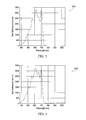
- FIG. 3 is a plot of the output of a miniature spectrometer that is measuring the output of a tungsten-halogen lamp when only light below wavelengths of approximately 750 nm is allowed to pass into the spectrometer, and second-order light is blocked from reaching the detector by a second-order filter.
- FIG. 4 is a plot of the output of a typical miniature spectrometer that is measuring the output of a tungsten-halogen lamp when only light below wavelengths of approximately 750 nm is allowed to pass into the spectrometer, and the second-order filter is removed and thus second-order light appears in the first-order wavelength range above 760 nm.
- FIG. 5 is a plot of the output of the spectrometer in FIG. 4 , except that the contribution from the second-order light has been removed by subtracting the calculated values, under an embodiment.
- Miniature spectrometers are operated over all or most of the wavelength range of 380-1050 nm, which is the overlap of the effective wavelength range of silicon-based array detectors (200-1050 nm) and tungsten-halogen light sources (380-2000 nm).
- Embodiments described herein correct errors due to the presence of second-order light using a method of correcting for second-order diffraction effects in spectrometers by processing the spectrometer output that contains the second-order diffraction response, i.e., without having to remove the second-order diffraction with costly optical filters. More particularly, embodiments described herein determine a relationship between first-order light and second-order light of the spectrometer output.
- the relationship is a function of wavelength and an output of the spectrometer due to the first-order light.
- the relationship is used to determine an estimated contribution of the second-order light to the output.
- Spectrometer errors introduced by the second-order light are corrected by adjusting the spectrometer output according to the estimated contribution of the second-order light.
- FIG. 1 is a flow diagram for correcting errors 100 due to the presence of second-order light, under an embodiment.
- Embodiments described herein generally correct errors due to the presence of second-order light by removing the second-order signal from the spectrometer output.
- Embodiments remove the second-order signal from the spectrometer output by determining 102 the relationship between the spectrometer output due to first-order and second-order light at each wavelength where there exists second-order light. This is done using the spectrometer output when no first-order light is input into the spectrometer in the wavelength range where there exists second-order light.
- the ratio of the second-order to first-order output is calculated 104 at each wavelength where there exists second-order light. The ratio is used to calculate 106 the expected amount of second-order light at each wavelength, and then this amount is subtracted from the spectrometer output at each wavelength.
- second-order light from the diffraction grating is proportional to the first-order light for each wavelength; the relationship between first-order light and second-order light can be determined as a function of wavelength; the relationship between first-order light and second-order light can be used along with the measured first-order light to determine the contribution of second-order light to a spectrometer's output in real time and to thus correct for the contribution of second-order light.
- FIG. 2 is a plot 200 of output from a miniature spectrometer that is measuring the output of a tungsten-halogen lamp.
- the output at each wavelength is a product of the lamp intensity and the response of the various spectrometer components, most notably the diffraction grating and the silicon detector array.
- the output decreases at shorter wavelengths primarily because the tungsten-halogen lamp intensity drops rapidly below wavelengths of approximately 500 nm.
- the output decreases at longer wavelengths primarily because the silicon detector array sensitivity drops rapidly above wavelengths of approximately 800 nm.
- the diffraction grating first-order efficiency also drops away above and below wavelengths in a range of approximately 500-600 nm.
- This particular spectrometer has a linearly-graded second-order filter in front of the detector array, so no second-order light is being detected or included in the plotted output.
- FIG. 3 is a plot 300 of the output of a miniature spectrometer that is measuring the output of a tungsten-halogen lamp when only light below wavelengths of approximately 750 nm is allowed to pass into the spectrometer.
- a second-order linear filter is positioned in front of the spectrometer detector array to remove second-order light from the wavelength range above 760 nm.
- the second-order linear filter is a high-pass filter positioned in front of the spectrometer's detector array. In front of the detector array's pixel that is meant to detect 1000 nm first-order light this second-order filter blocks the second-order light (500 nm in this case) and passes the 1000 nm first-order light.
- the same second-order filter must also pass the first-order light over the entire detector array. In practice this is accomplished by linearly grading the thicknesses of the filter's component film stack over the length of the detector array. In this way, for example, it can block 500 nm light in front of the 1000 nm pixel, while still passing 380 nm light in front of the 380 nm pixel. In this configuration there is no light input to the spectrometer above wavelengths of approximately 750 nm, and it can be seen that no significant amount of light is detected above wavelengths of approximately 750 nm. This last fact means that the second-order filter is successfully blocking second-order light from reaching the detector array.
- FIG. 4 is a plot 400 of the output of a typical miniature spectrometer that is measuring the output of a tungsten-halogen lamp when only light below a wavelength of approximately 750 nm is allowed to pass into the spectrometer.
- This plot 400 is obtained using the same equipment configuration as that used to obtain the plot 300 described above, except that the second-order filter has been removed. In this case it can be clearly seen that second-order light is reaching the detector array in the range of wavelengths of approximately 760-1050 nm.
- the second-order signal increases with wavelength at wavelengths between approximately 760-1050 nm because the intensity of the tungsten-halogen lamp increases strongly between approximately 380-525 nm. At a wavelength of approximately 1050 nm, the amount of second-order light (which is actually light of wavelength 525 nm) is nearly as strong as the first-order light seen in plot 100 . Clearly the second-order light will be a source of error if it is present and not corrected for.
- Embodiments described herein remove the second-order signal from the spectrometer output.
- the embodiments remove the second-order signal from the spectrometer output by determining, for the spectrometer of interest, the relationship between the spectrometer output due to first-order and second-order light at each wavelength ⁇ where there exists second-order light. This is done using the spectrometer output when no first-order light is input into the spectrometer in the wavelength range where there exists second-order light, such as under the conditions described above with reference to plot 400 .
- Embodiments then calculate the ratio (called here R 21 ( ⁇ )) of the second-order output I( ⁇ ) to first-order output (I( ⁇ /2)) at each wavelength where there exists second-order light, where I( ⁇ ) is the intensity (i.e., counts in FIG. 4 ) of the spectrometer output at wavelength ⁇ .
- R 21 ( ⁇ ) I( ⁇ )/I( ⁇ /2).
- this typically involves some interpolation because the spectrometer output is usually at discrete wavelengths corresponding to individual detector array pixels, and the pixels in the first-order wavelength range rarely fall at exactly one-half the wavelength of the second-order pixels.
- FIG. 5 shows a plot 500 the output of the spectrometer in plot 400 , except that the contribution from the second-order light has been removed by subtracting the calculated values, under an embodiment. Essentially the entire signal due to second-order order light has been removed and the spectrum looks effectively the same as that of the spectrometer with the second-order linear filter shown in plot 300 described above.
- Embodiments described herein include a system comprising a spectrometer.
- the system comprises an illumination source coupled to the spectrometer.
- a relationship is determined between first-order light output and second-order light output of the spectrometer.
- the relationship is a function of wavelength and first-order light output of the spectrometer.
- An estimated contribution of the second-order light output of the spectrometer is determined with the relationship.
- Spectrometer errors introduced by the second-order light output are corrected by adjusting the spectrometer output according to the estimated contribution.
- Embodiments described herein include a system comprising: a spectrometer; and an illumination source coupled to the spectrometer, wherein a relationship is determined between first-order light output and second-order light output of the spectrometer, wherein the relationship is a function of wavelength and first-order light output of the spectrometer, wherein an estimated contribution of the second-order light output of the spectrometer is determined with the relationship, wherein spectrometer errors introduced by the second-order light output are corrected by adjusting the spectrometer output according to the estimated contribution.
- a wavelength range of an embodiment that comprises second-order light is determined for the illumination source.
- the relationship of an embodiment comprises a ratio of a second-order output to a first-order output.
- the ratio of an embodiment is determined for a plurality of discrete wavelengths within a wavelength range.
- the estimated contribution of an embodiment is determined by calculating with use of the ratio the expected amount of second-order light.
- the estimated contribution of an embodiment is calculated by multiplying the ratio by the first-order output.
- the estimated contribution of an embodiment is determined for a plurality of discrete wavelengths within the wavelength range.
- the spectrometer output of an embodiment is adjusted by subtracting the estimated contribution of the second-order light from the spectrometer output.
- the wavelength range of an embodiment comprises a plurality of discrete wavelengths, wherein each discrete wavelength corresponds to a set of pixels of a detector of the spectrometer.
- the spectrometer errors of an embodiment are corrected for by removing signal due to second-order light from an output of the spectrometer instead of positioning a linear-filter in front of the detector.
- the illumination of an embodiment is controlled by diffracting light of the illumination source.
- the second-order light of an embodiment is proportional to first-order light.
- a relationship between the first-order light and the second-order light of an embodiment is a function of wavelength.
- a relationship of an embodiment is used between the first-order light and the second-order light along with measured first-order light to determine a contribution of the second-order light to an output of the spectrometer.
- Embodiments described herein include a system comprising a spectrometer.
- the system comprises an illumination source coupled to the spectrometer.
- a relationship is determined between first-order light output and second-order light output of the spectrometer.
- the relationship is a function of the first-order light output of the spectrometer.
- An estimated contribution of the second-order light output of the spectrometer is determined with the relationship.
- Spectrometer errors introduced by the second-order light output are corrected by subtracting the estimated contribution from the spectrometer output.
- Embodiments described herein include a system comprising: a spectrometer; and an illumination source coupled to the spectrometer, wherein a relationship is determined between first-order light output and second-order light output of the spectrometer, wherein the relationship is a function of the first-order light output of the spectrometer, wherein an estimated contribution of the second-order light output of the spectrometer is determined with the relationship, wherein spectrometer errors introduced by the second-order light output are corrected by subtracting the estimated contribution from the spectrometer output.
- Embodiments described herein include a method comprising coupling an illumination source to a spectrometer.
- the method comprises determining a relationship between first-order light and second-order light output by the spectrometer.
- the relationship is a function of wavelength and an output of the spectrometer due to the first-order light.
- the method comprises determining by using the relationship an estimated contribution of the second-order light to the output.
- the method comprises correcting for spectrometer errors introduced by the second-order light by adjusting the spectrometer output according to the estimated contribution of the second-order light.
- Embodiments described herein include a method comprising: coupling an illumination source to a spectrometer; determining a relationship between first-order light and second-order light output by the spectrometer, wherein the relationship is a function of wavelength and an output of the spectrometer due to the first-order light; determining by using the relationship an estimated contribution of the second-order light to the output; and correcting for spectrometer errors introduced by the second-order light by adjusting the spectrometer output according to the estimated contribution of the second-order light.
- the determining of the relationship of an embodiment comprises controlling the illumination source to prevent admission of the first-order light in a wavelength range that comprises the second-order light.
- the method of an embodiment comprises determining for the illumination source a wavelength range that comprises second-order light.
- the determining of the estimated contribution of an embodiment comprises determining an expected amount of second-order light at each of the wavelengths.
- the determining of the relationship of an embodiment comprises determining a ratio of a second-order light output to a first-order light output.
- the method of an embodiment comprises determining the ratio for a plurality of discrete wavelengths within the wavelength range.
- the determining of the estimated contribution of an embodiment comprises calculating with use of the ratio the estimated contribution of second-order light output.
- the calculating of the estimated contribution of an embodiment comprises multiplying the ratio by the first-order light output.
- the method of an embodiment comprises determining the estimated contribution for a plurality of discrete wavelengths within the wavelength range.
- the adjusting of the spectrometer output of an embodiment comprises subtracting the estimated contribution of the second-order light output from the spectrometer output.
- the wavelength range of an embodiment comprises a plurality of discrete wavelengths, wherein each discrete wavelength corresponds to a set of pixels of a detector of the spectrometer.
- the correcting for the spectrometer errors of an embodiment comprises removing signal due to second-order light output from an output of the spectrometer instead of positioning a linear-filter in front of the detector.
- the controlling of the illumination of an embodiment comprises diffracting light of the illumination source.
- the second-order light is proportional to first-order light.
- the method of an embodiment comprises using a relationship between the first-order light and the second-order light along with measured first-order light to determine a contribution of the second-order light to an output of the spectrometer.
- Embodiments described herein include a method comprising determining a relationship between first-order light and second-order light output by the spectrometer.
- the relationship is a function of an output of the spectrometer due to the first-order light.
- the method comprises determining by using the relationship an estimated contribution of the second-order light to the output.
- the method comprises correcting for spectrometer errors introduced by the second-order light by subtracting the estimated contribution from the spectrometer output.
- Embodiments described herein include a method comprising: determining a relationship between first-order light and second-order light output by the spectrometer, wherein the relationship is a function of an output of the spectrometer due to the first-order light; determining by using the relationship an estimated contribution of the second-order light to the output; and correcting for spectrometer errors introduced by the second-order light by subtracting the estimated contribution from the spectrometer output.
- Embodiments described herein include a method comprising controlling an illumination source of a spectrometer to prevent admission of first-order light in a wavelength range that comprises second-order light.
- the method comprises determining for wavelengths within the wavelength range a relationship between an output of the spectrometer due to first-order light and the output due to second-order light.
- the method comprises determining with use of the relationship an expected amount of second-order light at each of the wavelengths.
- the method comprises correcting for spectrometer errors due to presence of the second-order light by adjusting the spectrometer output according to the expected amount of the second-order light.
- Embodiments described herein include a method comprising: controlling an illumination source of a spectrometer to prevent admission of first-order light in a wavelength range that comprises second-order light; determining for wavelengths within the wavelength range a relationship between an output of the spectrometer due to first-order light and the output due to second-order light; determining with use of the relationship an expected amount of second-order light at each of the wavelengths; and correcting for spectrometer errors due to presence of the second-order light by adjusting the spectrometer output according to the expected amount of the second-order light.
- Embodiments described herein include a method comprising determining spectrometer output absent first-order light input in a wavelength range where there exists second-order light.
- the method comprises determining for the wavelength range a relationship between the spectrometer output due to the first-order light and spectrometer output due to second-order light at each wavelength where there exists second-order light.
- the method comprises correcting for the second-order light by using the relationship to calculate an expected amount of the second-order light at each wavelength, and subtracting the expected amount of the second-order light from the spectrometer output at each wavelength.
- Embodiments described herein include a method comprising: determining spectrometer output absent first-order light input in a wavelength range where there exists second-order light; determining for the wavelength range a relationship between the spectrometer output due to the first-order light and spectrometer output due to second-order light at each wavelength where there exists second-order light; and correcting for the second-order light by using the relationship to calculate an expected amount of the second-order light at each wavelength, and subtracting the expected amount of the second-order light from the spectrometer output at each wavelength.
- the words “comprise,” “comprising,” and the like are to be construed in an inclusive sense as opposed to an exclusive or exhaustive sense; that is to say, in a sense of “including, but not limited to.” Words using the singular or plural number also include the plural or singular number respectively. Additionally, the words “herein,” “hereunder,” “above,” “below,” and words of similar import refer to this application as a whole and not to any particular portions of this application. When the word “or” is used in reference to a list of two or more items, that word covers all of the following interpretations of the word: any of the items in the list, all of the items in the list and any combination of the items in the list.
- the terms used should not be construed to limit the spectrometer systems and methods to the specific embodiments disclosed in the specification and the claims, but should be construed to include all systems and methods that operate under the claims. Accordingly, the spectrometer systems and methods are not limited by the disclosure, but instead the scope of the spectrometer systems and methods is to be determined entirely by the claims.
Abstract
Description
Claims (31)
Priority Applications (1)
| Application Number | Priority Date | Filing Date | Title |
|---|---|---|---|
| US13/743,038 US8908177B2 (en) | 2012-01-16 | 2013-01-16 | Correction of second-order diffraction effects in fiber-optic-based spectrometers |
Applications Claiming Priority (2)
| Application Number | Priority Date | Filing Date | Title |
|---|---|---|---|
| US201261586943P | 2012-01-16 | 2012-01-16 | |
| US13/743,038 US8908177B2 (en) | 2012-01-16 | 2013-01-16 | Correction of second-order diffraction effects in fiber-optic-based spectrometers |
Publications (2)
| Publication Number | Publication Date |
|---|---|
| US20130258333A1 US20130258333A1 (en) | 2013-10-03 |
| US8908177B2 true US8908177B2 (en) | 2014-12-09 |
Family
ID=49234600
Family Applications (1)
| Application Number | Title | Priority Date | Filing Date |
|---|---|---|---|
| US13/743,038 Active US8908177B2 (en) | 2012-01-16 | 2013-01-16 | Correction of second-order diffraction effects in fiber-optic-based spectrometers |
Country Status (1)
| Country | Link |
|---|---|
| US (1) | US8908177B2 (en) |
Cited By (1)
| Publication number | Priority date | Publication date | Assignee | Title |
|---|---|---|---|---|
| CN110487404A (en) * | 2019-09-25 | 2019-11-22 | 台州市维谱智能科技有限公司 | A method of eliminating grating spectrograph Advanced Diffraction influences |
Families Citing this family (2)
| Publication number | Priority date | Publication date | Assignee | Title |
|---|---|---|---|---|
| JP5987573B2 (en) * | 2012-09-12 | 2016-09-07 | セイコーエプソン株式会社 | Optical module, electronic device, and driving method |
| US9188486B1 (en) | 2014-08-11 | 2015-11-17 | Datacolor Holding Ag | System and method for compensating for second order diffraction in spectrometer measurements |
Citations (1)
| Publication number | Priority date | Publication date | Assignee | Title |
|---|---|---|---|---|
| US4927269A (en) * | 1989-01-31 | 1990-05-22 | Bruke Analytische Messtechnik Gmbh | Correction of non-linearities in detectors in fourier transform spectroscopy |
-
2013
- 2013-01-16 US US13/743,038 patent/US8908177B2/en active Active
Patent Citations (1)
| Publication number | Priority date | Publication date | Assignee | Title |
|---|---|---|---|---|
| US4927269A (en) * | 1989-01-31 | 1990-05-22 | Bruke Analytische Messtechnik Gmbh | Correction of non-linearities in detectors in fourier transform spectroscopy |
Cited By (1)
| Publication number | Priority date | Publication date | Assignee | Title |
|---|---|---|---|---|
| CN110487404A (en) * | 2019-09-25 | 2019-11-22 | 台州市维谱智能科技有限公司 | A method of eliminating grating spectrograph Advanced Diffraction influences |
Also Published As
| Publication number | Publication date |
|---|---|
| US20130258333A1 (en) | 2013-10-03 |
Similar Documents
| Publication | Publication Date | Title |
|---|---|---|
| Thorburn et al. | Some diffuse interstellar bands related to interstellar C2 molecules | |
| JP5630091B2 (en) | Spectrometer | |
| JP2006153770A (en) | Spectral measurement apparatus | |
| US8908177B2 (en) | Correction of second-order diffraction effects in fiber-optic-based spectrometers | |
| JP2013072874A (en) | Integrated three-channel gas detection and measurement spectrometer | |
| JP2013072874A5 (en) | ||
| US10393585B2 (en) | Spectral detector and spectral detecting method using the same | |
| JP2012506562A (en) | Spectrometer comprising an aberration correcting concave diffraction grating and transmission aberration correcting means | |
| JP2009222690A (en) | Spectrometric measuring instrument and spectrometric measuring method | |
| JP5707739B2 (en) | Spectrometer | |
| US20120105847A1 (en) | Spectrometric measurement system and method for compensating for veiling glare | |
| WO2003069291A1 (en) | Photopolarimeters and spectrophotopolarimaters with multiple diffraction gratings | |
| IL273731B2 (en) | Metrology method | |
| KR101683465B1 (en) | In-situ calibration method of spectroscopy using multiple emission sources | |
| JP2018054337A (en) | Spectroscopic analyzer and calibration method | |
| JP2015152347A (en) | Spectroscopic analyzer and spectroscopic analysis method | |
| KR101054017B1 (en) | Calibration method of the spectrometer | |
| US10514300B2 (en) | Spectrocolorimetric device and conversation rule setting method | |
| CN116222783B (en) | Spectrum measuring device and method | |
| Imura et al. | Practical method for correcting heterochromatic stray light in dual‐channel spectrographs for colorimetry | |
| US20200018649A1 (en) | Imaging Spectrograph Utilizing the Zero Order of the Diffraction Grating | |
| JP7394319B2 (en) | Adaptive optics analyzer with automatic drift control and high dynamic range | |
| KR20160063524A (en) | Wide range spectrometer including multiple crystals | |
| US20110188036A1 (en) | Monochromatic measurement system | |
| JP5915714B2 (en) | Spectrometer |
Legal Events
| Date | Code | Title | Description |
|---|---|---|---|
| AS | Assignment |
Owner name: FILMETRICS, INC., CALIFORNIA Free format text: ASSIGNMENT OF ASSIGNORS INTEREST;ASSIGNORS:CHALMERS, SCOTT A.;GEELS, RANDALL S.;REEL/FRAME:030626/0688 Effective date: 20130513 |
|
| STCF | Information on status: patent grant |
Free format text: PATENTED CASE |
|
| FEPP | Fee payment procedure |
Free format text: MAINTENANCE FEE REMINDER MAILED (ORIGINAL EVENT CODE: REM.) |
|
| FEPP | Fee payment procedure |
Free format text: SURCHARGE FOR LATE PAYMENT, SMALL ENTITY (ORIGINAL EVENT CODE: M2554) |
|
| MAFP | Maintenance fee payment |
Free format text: PAYMENT OF MAINTENANCE FEE, 4TH YR, SMALL ENTITY (ORIGINAL EVENT CODE: M2551) Year of fee payment: 4 |
|
| FEPP | Fee payment procedure |
Free format text: ENTITY STATUS SET TO UNDISCOUNTED (ORIGINAL EVENT CODE: BIG.); ENTITY STATUS OF PATENT OWNER: LARGE ENTITY |
|
| MAFP | Maintenance fee payment |
Free format text: PAYMENT OF MAINTENANCE FEE, 8TH YEAR, LARGE ENTITY (ORIGINAL EVENT CODE: M1552); ENTITY STATUS OF PATENT OWNER: LARGE ENTITY Year of fee payment: 8 |
|
| AS | Assignment |
Owner name: KLA-TENCOR CORPORATION, CALIFORNIA Free format text: ASSIGNMENT OF ASSIGNORS INTEREST;ASSIGNOR:FILMETRICS, INC.;REEL/FRAME:066832/0987 Effective date: 20240318 |