US8905587B1 - Internal covert IR filter for searchlight systems - Google Patents

Internal covert IR filter for searchlight systems Download PDF

Info

Publication number
US8905587B1
US8905587B1 US13/206,208 US201113206208A US8905587B1 US 8905587 B1 US8905587 B1 US 8905587B1 US 201113206208 A US201113206208 A US 201113206208A US 8905587 B1 US8905587 B1 US 8905587B1
Authority
US
United States
Prior art keywords
light
cover
reflector
lamp
section
Prior art date
Legal status (The legal status is an assumption and is not a legal conclusion. Google has not performed a legal analysis and makes no representation as to the accuracy of the status listed.)
Active, expires
Application number
US13/206,208
Inventor
Anton M. Bouckaert
Current Assignee (The listed assignees may be inaccurate. Google has not performed a legal analysis and makes no representation or warranty as to the accuracy of the list.)
Boeing Co
Original Assignee
Boeing Co
Priority date (The priority date is an assumption and is not a legal conclusion. Google has not performed a legal analysis and makes no representation as to the accuracy of the date listed.)
Filing date
Publication date
Application filed by Boeing Co filed Critical Boeing Co
Priority to US13/206,208 priority Critical patent/US8905587B1/en
Assigned to THE BOEING COMPANY reassignment THE BOEING COMPANY ASSIGNMENT OF ASSIGNORS INTEREST (SEE DOCUMENT FOR DETAILS). Assignors: BOUCKAERT, ANTON M.
Application granted granted Critical
Publication of US8905587B1 publication Critical patent/US8905587B1/en
Active legal-status Critical Current
Adjusted expiration legal-status Critical

Links

Images

Classifications

    • FMECHANICAL ENGINEERING; LIGHTING; HEATING; WEAPONS; BLASTING
    • F21LIGHTING
    • F21VFUNCTIONAL FEATURES OR DETAILS OF LIGHTING DEVICES OR SYSTEMS THEREOF; STRUCTURAL COMBINATIONS OF LIGHTING DEVICES WITH OTHER ARTICLES, NOT OTHERWISE PROVIDED FOR
    • F21V9/00Elements for modifying spectral properties, polarisation or intensity of the light emitted, e.g. filters
    • F21V9/04Elements for modifying spectral properties, polarisation or intensity of the light emitted, e.g. filters for filtering out infrared radiation
    • F21S48/1136
    • FMECHANICAL ENGINEERING; LIGHTING; HEATING; WEAPONS; BLASTING
    • F21LIGHTING
    • F21VFUNCTIONAL FEATURES OR DETAILS OF LIGHTING DEVICES OR SYSTEMS THEREOF; STRUCTURAL COMBINATIONS OF LIGHTING DEVICES WITH OTHER ARTICLES, NOT OTHERWISE PROVIDED FOR
    • F21V7/00Reflectors for light sources
    • F21V7/22Reflectors for light sources characterised by materials, surface treatments or coatings, e.g. dichroic reflectors
    • F21V7/24Reflectors for light sources characterised by materials, surface treatments or coatings, e.g. dichroic reflectors characterised by the material
    • FMECHANICAL ENGINEERING; LIGHTING; HEATING; WEAPONS; BLASTING
    • F21LIGHTING
    • F21VFUNCTIONAL FEATURES OR DETAILS OF LIGHTING DEVICES OR SYSTEMS THEREOF; STRUCTURAL COMBINATIONS OF LIGHTING DEVICES WITH OTHER ARTICLES, NOT OTHERWISE PROVIDED FOR
    • F21V7/00Reflectors for light sources
    • F21V7/22Reflectors for light sources characterised by materials, surface treatments or coatings, e.g. dichroic reflectors
    • F21V7/28Reflectors for light sources characterised by materials, surface treatments or coatings, e.g. dichroic reflectors characterised by coatings
    • FMECHANICAL ENGINEERING; LIGHTING; HEATING; WEAPONS; BLASTING
    • F21LIGHTING
    • F21VFUNCTIONAL FEATURES OR DETAILS OF LIGHTING DEVICES OR SYSTEMS THEREOF; STRUCTURAL COMBINATIONS OF LIGHTING DEVICES WITH OTHER ARTICLES, NOT OTHERWISE PROVIDED FOR
    • F21V13/00Producing particular characteristics or distribution of the light emitted by means of a combination of elements specified in two or more of main groups F21V1/00 - F21V11/00
    • F21V13/02Combinations of only two kinds of elements
    • F21V13/08Combinations of only two kinds of elements the elements being filters or photoluminescent elements and reflectors
    • FMECHANICAL ENGINEERING; LIGHTING; HEATING; WEAPONS; BLASTING
    • F21LIGHTING
    • F21VFUNCTIONAL FEATURES OR DETAILS OF LIGHTING DEVICES OR SYSTEMS THEREOF; STRUCTURAL COMBINATIONS OF LIGHTING DEVICES WITH OTHER ARTICLES, NOT OTHERWISE PROVIDED FOR
    • F21V14/00Controlling the distribution of the light emitted by adjustment of elements
    • F21V14/08Controlling the distribution of the light emitted by adjustment of elements by movement of the screens or filters
    • FMECHANICAL ENGINEERING; LIGHTING; HEATING; WEAPONS; BLASTING
    • F21LIGHTING
    • F21VFUNCTIONAL FEATURES OR DETAILS OF LIGHTING DEVICES OR SYSTEMS THEREOF; STRUCTURAL COMBINATIONS OF LIGHTING DEVICES WITH OTHER ARTICLES, NOT OTHERWISE PROVIDED FOR
    • F21V7/00Reflectors for light sources
    • F21V7/04Optical design
    • F21V7/06Optical design with parabolic curvature

Definitions

  • the present invention relates to searchlights and more particularly to covert infrared filters for selectively filtering the light source of a searchlight.
  • Vehicles such as aircraft, generally have lights mounted thereon for providing illumination during take-off, landing, or during search operations.
  • the lights may also be useful for identifying aircraft or providing primary or supplemental lighting during operation of the aircraft in adverse conditions, including night operations, rain, and other particle storms.
  • searchlights may be hand held or used in a smaller configuration, such as a flashlight, headlamp, or night vision imaging device.
  • One method of early convertible night-vision compatible lighting systems utilized a filter over the searchlight cover that allows only infrared light to pass through the filter. This type of filter, however, may be undesirable because of the difficulty in removing or altering the filter, requiring manual access to the searchlight. This limitation restricted the usefulness of the product by limiting flights to either visible-light or infrared-light.
  • a further improvement was the use of a lamp within a lighting system that has both a visible and an infrared filaments, allowing the operator to switch between the two. Further controls allowed the lamp head to be extended, retracted, and rotated through the use of electrical relays and a selector switch.
  • This improvement is described in U.S. Pat. No. 5,695,272 to Snyder et al.
  • U.S. Pat. No. 6,962,423 to Hamilton et al. describes another multi-mode visible and infrared lighthead for use as a landing light or searchlight.
  • This patent describes two separate diodes, one for emitting infrared and the other for emitting visible light, spaced apart in a searchlight with each diode having its own reflector and lens cover.
  • this arrangement similarly limits the amount of light that may be transmitted from the searchlight by dedicating a portion of the light-producing elements to only the infrared or visible spectrum.
  • This integrated searchlight lighthead includes separate infrared and visible light illumination sources each positioned within a reflector.
  • the reflectors are merged and separated by an insulating material and air gap, providing cooling of the illumination sources.
  • the merged reflector assembly provides an improved light distribution over previous light sources.
  • the merged reflectors are inferior to a single reflector and the combination of separate lighting elements reduces the intensity of the light that may be produced.
  • a method for converting the light output from a searchlight from a first light profile to a second light profile is disclosed.
  • This method generally requires the steps of providing a searchlight that includes a reflector and a lamp.
  • a substantially cylindrical lamp cover is positioned about the lamp that includes a first portion and a second portion. Light projected through the first section conforms to the first light profile and light projected through the second section conforms to the second light profile.
  • the lamp cover may be moved from a first position where light shines through the first position to a second position where light shines through the second portion. In this manner, the light is converted from the first light profile to the second light profile.
  • first portion may be clear glass with no filtering elements and the second portion may be glass having an infrared filtering component.
  • Other arrangements and filters are anticipated as well.
  • the apparatus generally includes a bowl-shaped reflector with an interior and an edge, a lamp within the interior of the reflector surface, a cover about the edge of the reflector, and a lamp cover about the lamp.
  • the lamp cover may include first and second sections having different light filtering characteristics.
  • An actuator is further included that moves the lamp cover from a first position to a second, such that in the first position light is projected from the lamp through the first section and in the second position light is projected from the lamp through the second section.
  • the first portion may include no filtering characteristics and the second portion may include infrared-pass filtering characteristics.
  • the lamp may also be attached to the actuator so that the lamp, lamp cover, and actuator may all be moved relative to the reflector. Other arrangements and filters are anticipated.
  • a method of manufacture includes the steps of providing a number of optically transparent flat segments and coating to a portion of the flat segments.
  • the segments are arranged in a substantially circular arrangement to form a lamp cover that can be moved to expose a lamp in a spotlight to either the transparent or coated portions of the flat segments. This provides selective filtering for the lamp and spotlight.
  • FIG. 1 is a plan view of a searchlight according to one embodiment.
  • FIG. 2 is a side cutaway view of the searchlight.
  • FIG. 3 is a perspective view of a light cover according to one embodiment.
  • FIG. 4 is a side plan view of the searchlight light source and actuator.
  • FIG. 5A is a side plan view of the light cover and actuator in a first arrangement.
  • FIG. 5B is a side plan view of the light cover and actuator in a second arrangement.
  • FIG. 6 is a perspective view of the actuator.
  • FIG. 7A is a perspective view of an alternative embodiment of the light cover.
  • FIG. 7B is a top plan view of a section of the light cover shown in FIG. 7A .
  • FIG. 1 illustrates one embodiment of the searchlight 100 including a housing 102 , light source 104 , reflector 106 , and a lens or cover 108 .
  • an improved light cover 110 is an improved light cover 110 about the light source 104 for selective filtering of light emitted by the source.
  • FIG. 2 shows a cutaway view of the searchlight 100 with the housing 102 and cover 108 removed.
  • the reflector 106 generally consists of a parabolic shape which may be formed of a highly reflective material (such as nickel) or include a highly reflective coating on the inner surface of the reflector 106 .
  • the reflector 106 may take on various cross-sectional shapes, including semi-circular or elliptical. Further, the material or coating for the reflector 106 may be selected to meet design objectives.
  • the light source 104 may be generally selected to be a high efficiency and ultra-bright lamp.
  • light source 104 may be a xenon arc lamp that utilizes electricity to excite ionized xenon gas to produce a bright white light between two electrodes.
  • Other lamps, including metal halide, mercury arc, sodium vapor, or other high intensity discharge (HID) lamps may be utilized in the searchlight.
  • Other non-HID lamps may be utilized as well, including light emitting diodes (LEDs), fluorescent, or incandescent bulbs may be used without departing from the scope of the disclosure.
  • the light source 104 is shown at the focal point of the parabola shape of the reflector 106 , however those having skill in the art will recognize that the light source 104 is movable away from the focal point of the reflector 106 to focus or widen the light projected from the searchlight.
  • the light cover 110 which substantially encircles the light source 104 ( FIG. 2 ).
  • This light cover 110 may include a clear section 112 and a filtering section 114 .
  • the clear section 112 is designed to allow all wavelengths of light from the light source 104 to pass through the light cover 110 , allowing the searchlight to be used in a normal operating mode.
  • the filtering section 114 is positioned on a separate part of the light cover 110 and only allows selective wavelengths of light to pass through the cover 110 .
  • the filtering section 114 may include an infrared filter, preventing visible and ultraviolet light from passing through the light cover 110 while allowing infrared light to pass through.
  • the light cover 110 may be a substantially cylindrical cover, comprised of a transparent material to provide a clear portion 112 .
  • a filtering material may be applied to provide a filtering portion 114 of the light cover 110 .
  • the light cover 110 is shown as having a generally cylindrical shape with a circular cross section but it is contemplated that the light cover 110 may comprise a variety of cross sections, including but not limited to continuous or non-continuous curves, regular and irregular geometric figures, and symmetrical or non-symmetrical curves, including ellipses or other closed figures. Further, while the light cover 110 is shown as having a consistent cross section across its entire length, it is contemplated that the light filter may have a continuous or varied cross section along its length, including a narrowing, widening, or otherwise geometrically changing cross section.
  • the use of distinct clear and infrared-filtering sections on the light cover is merely exemplary, and other combinations may be utilized without departing from the scope of the disclosure.
  • Other filters or shutters for limiting the wavelengths or amount of light that passes through the light cover 110 will be known to those having skill in the art, and may include some combination of a clear, colored, ultraviolet, infrared, or multiple-wavelength light filter.
  • the light cover 110 is not limited to two separate and distinct regions. It is contemplated that three or more regions, including gradual filtering from one region to the next, may be utilized in combination with the light cover 110 , or that several filtered layers may be stacked to allow for varied filtering options.
  • the light cover 110 In order to switch between the clear 112 and infrared 114 sections of the light cover 110 , the light cover 110 must be moved relative to the bulb by means of an actuator 116 shown in FIGS. 4 and 5 A-B, such as an electronic actuator. This actuator 116 positions the light cover 110 so that the preferred portion, whether it is the clear 112 or infrared-filtering 114 portion, substantially surrounds the light source 104 .
  • the actuator is generally positioned outside of the reflector 106 and is movable with the light source 104 relative to the reflector.
  • This arrangement allows the filter and light source to move together to adjust the light output of the searchlight as the beam is narrowed or widened. This prevents light leakage from around either the clear section 112 or filtering section 114 of the light cover 110 when the light source 104 is moved, which may be undesirable depending on the use of the searchlight.
  • FIGS. 5A and 5B illustrate a side cutaway view of the reflector 100 showing the light cover 110 in a first ( FIG. 5A ) and second ( FIG. 5B ) position, thereby exposing the light source 104 to the clear 112 and filtering 114 sections of the cover 110 .
  • the light cover 110 is in a first position whereby the clear section 112 of the light cover 110 surrounds the light source 104 .
  • the light source 104 may generally consist of an anode 118 , a glass bulb 120 , and a cathode 122 opposite the anode 118 .
  • an electrical current is passed from the anode 118 to the cathode 122 and exciting the gas within the glass bulb 120 .
  • xenon gas creates a bright white light that radiates away from the gas and through the glass bulb 120 . While white light produced from xenon is one embodiment, it is understood that other gas sources may be used to create other colors of light.
  • light rays 124 are emitted from the glass bulb 120 and extend radially away from the bulb 120 .
  • the light rays 124 then pass through the light cover 110 and are reflected off of the reflector 106 ( FIG. 2 ).
  • the reflector 106 is generally shown to be a parabolic reflector which aligns light rays 124 to be substantially parallel as they pass through the cover 108 .
  • the clear portion 112 of the light cover 110 is positioned about the light source 104 , allowing light rays 124 of all wavelengths to pass through the light cover 110 .
  • FIG. 5B shows the light cover 110 in a second position where the filtered portion 114 of the light cover 110 substantially covers the light source 104 , or more particularly, the gas-filled light emitting glass bulb 120 .
  • light rays 124 are emitted from the xenon gas within the glass bulb 120 as described above.
  • a layer of filtering material on the filtered portion 114 of the light cover 110 absorbs or reflects non-preferred wavelengths of light. In the example described, this filter allows only infrared light to pass through while reflecting or absorbing non-infrared light. Rays of infrared light 126 are then reflected from the reflector surface 106 and pass through the cover 108 .
  • the actuator 116 which controls the position of light cover 110 .
  • This actuator 116 moves the light cover 110 from the first to second position so that rays of light 126 engage either the clear section 112 or filtering section 114 of the light cover 110 .
  • the actuator 116 includes a motor (not shown), inner sleeve 119 and outer sleeve 121 .
  • the outer sleeve 121 includes a spiral slot 125 that extends radially and axially about the outer sleeve 121 .
  • the inner sleeve 119 includes a straight slot 127 that extends only axially about the inner sleeve. As shown in FIGS.
  • an anchor 123 is provided on the light cover 110 that extends through the spiral 125 and straight 127 slots.
  • the slots 125 , 127 are sized to approximately the same size as the anchor 123 , and therefore movement of the anchor is constrained by the positions of the inner 119 and outer sleeves 121 to each other.
  • the motor may be connected alternatively to the inner 119 or outer 121 sleeves to rotate one relative to the other when the motor is engaged. Because the slots 125 , 127 constrain the position of the anchor 123 , as the outer sleeve 121 is rotated relative to the inner sleeve 119 , the anchor traverses the spiral slot 125 radially while traversing the straight slot 127 axially.
  • reflector 106 and actuator 116 are coupled to move with one another. This coupling allows adjustment of the light source 104 relative to the reflector 106 without adjusting the position of the reflector 106 relative to the light cover 110 . This is to maintain the integrity of the light seal 128 ( FIGS. 5A and 5B ) around the light cover 110 , preventing light of unwanted wavelengths from leaking out, which may compromise the purpose of utilizing an infrared filter.
  • FIG. 7A shows a perspective view of an alternative embodiment of the light cover 110 .
  • the light cover 110 preferably includes a clear portion 112 and a filtered portion 114 adjacent to one another such that the light cover 110 may selectively filter a light source 104 ( FIG. 2 ).
  • the light cover 110 may be constructed from a number of multiple flat segments 132 .
  • An exemplar of these multiple flat segments 132 is shown in FIG. 7B .
  • Each segment 132 may include a clear section 112 and a filtering section 114 as described above, and according to the embodiment illustrated, all of the flat segments may be substantially identical.
  • the segments 132 may be constructed, for example, of flat segments of quartz glass with a portion having an infrared sapphire coating or coated using another existing infrared filter coating. However, it should be understood by those having skill in the art that the shape, size, and material of the segments 132 may vary without departing from the scope of the disclosure.
  • This method includes the steps of providing a searchlight 100 as described, generally including a housing 102 , light source 104 , reflector 106 , cover 108 and light cover 110 .
  • the light cover 110 is positioned about the light source 104 as described above and is movable between first and second positions. In each of the first and second positions either of a clear 112 or filtered section 114 , respectively, are positioned to capture light emitted from the light source 104 .
  • the light source 104 projects light through either the clear section 112 of the light cover 110 .
  • an actuator 116 may be engaged to move the light cover 110 to the second position, thereby surrounding the light source 104 with the filtered section 114 of the light cover 110 . Movement of the light cover 110 may by means of electronic, manual, mechanical, hydraulic, or other known control system.

Landscapes

  • Engineering & Computer Science (AREA)
  • General Engineering & Computer Science (AREA)
  • Physics & Mathematics (AREA)
  • Spectroscopy & Molecular Physics (AREA)
  • Securing Globes, Refractors, Reflectors Or The Like (AREA)
  • Non-Portable Lighting Devices Or Systems Thereof (AREA)

Abstract

Described in this application for patent is a novel method and apparatus for modifying a searchlight from a visible-light source to an infrared source. This selective filtering is accomplished by means of a partially filtered cover about the light source which may be moved between first and second positions. In a first position, light projected by the light source passes through an unfiltered section of the lamp cover. In a second position, light projected by the light source passes through a filtered section of the lamp cover.

Description

BACKGROUND
The present invention relates to searchlights and more particularly to covert infrared filters for selectively filtering the light source of a searchlight.
Vehicles, such as aircraft, generally have lights mounted thereon for providing illumination during take-off, landing, or during search operations. The lights may also be useful for identifying aircraft or providing primary or supplemental lighting during operation of the aircraft in adverse conditions, including night operations, rain, and other particle storms. Alternatively, searchlights may be hand held or used in a smaller configuration, such as a flashlight, headlamp, or night vision imaging device.
With the advent of night vision imaging systems for covert operations, a need has arisen for landing lights, searchlights, and portable light sources that are compatible with night vision by producing infrared light. While separate infrared and visible spectrum lights may accomplish these objectives, there has been recognized a need in the art for a light source which may be converted between infrared and visible illumination.
One method of early convertible night-vision compatible lighting systems utilized a filter over the searchlight cover that allows only infrared light to pass through the filter. This type of filter, however, may be undesirable because of the difficulty in removing or altering the filter, requiring manual access to the searchlight. This limitation restricted the usefulness of the product by limiting flights to either visible-light or infrared-light.
A further improvement was the use of a lamp within a lighting system that has both a visible and an infrared filaments, allowing the operator to switch between the two. Further controls allowed the lamp head to be extended, retracted, and rotated through the use of electrical relays and a selector switch. One example of this improvement is described in U.S. Pat. No. 5,695,272 to Snyder et al.
This improvement allowed significant advantages over the prior art, including the ability to switch between the infrared and visible light spectrum from within the cockpit, thereby eliminating the need to manually remove and replace the searchlight cover to switch modes. However, these lamps do not emit the same intensity as a dedicated infrared or visible light system as the bulb surface is divided between infrared and visible light filtering covers.
U.S. Pat. No. 6,962,423 to Hamilton et al. describes another multi-mode visible and infrared lighthead for use as a landing light or searchlight. This patent describes two separate diodes, one for emitting infrared and the other for emitting visible light, spaced apart in a searchlight with each diode having its own reflector and lens cover. However, this arrangement similarly limits the amount of light that may be transmitted from the searchlight by dedicating a portion of the light-producing elements to only the infrared or visible spectrum.
Another dual mode searchlight is described in U.S. Pat. No. 7,518,133 to Giffen et al. This integrated searchlight lighthead includes separate infrared and visible light illumination sources each positioned within a reflector. The reflectors are merged and separated by an insulating material and air gap, providing cooling of the illumination sources. The merged reflector assembly provides an improved light distribution over previous light sources. However, the merged reflectors are inferior to a single reflector and the combination of separate lighting elements reduces the intensity of the light that may be produced.
Therefore, there has been recognized a need in the art for an improved searchlight capable of selectively transmitting infrared or visible light. There is further a need in the art for an improved searchlight which can be easily switched between infrared and visible illumination without the need for modification of the searchlight housing or cover. Finally, there is a need in the art for an improved searchlight which improves light distribution and efficiency.
SUMMARY
According to one embodiment of the following description a method for converting the light output from a searchlight from a first light profile to a second light profile is disclosed. This method generally requires the steps of providing a searchlight that includes a reflector and a lamp. A substantially cylindrical lamp cover is positioned about the lamp that includes a first portion and a second portion. Light projected through the first section conforms to the first light profile and light projected through the second section conforms to the second light profile. The lamp cover may be moved from a first position where light shines through the first position to a second position where light shines through the second portion. In this manner, the light is converted from the first light profile to the second light profile.
Further improvements on this apparatus include providing that the first portion may be clear glass with no filtering elements and the second portion may be glass having an infrared filtering component. Other arrangements and filters are anticipated as well.
According to a further embodiment, the following description describes an apparatus for providing either filtered or unfiltered light. The apparatus generally includes a bowl-shaped reflector with an interior and an edge, a lamp within the interior of the reflector surface, a cover about the edge of the reflector, and a lamp cover about the lamp. The lamp cover may include first and second sections having different light filtering characteristics. An actuator is further included that moves the lamp cover from a first position to a second, such that in the first position light is projected from the lamp through the first section and in the second position light is projected from the lamp through the second section.
According to further embodiments, the first portion may include no filtering characteristics and the second portion may include infrared-pass filtering characteristics. The lamp may also be attached to the actuator so that the lamp, lamp cover, and actuator may all be moved relative to the reflector. Other arrangements and filters are anticipated.
According to yet another embodiment, a method of manufacture is described. This method includes the steps of providing a number of optically transparent flat segments and coating to a portion of the flat segments. The segments are arranged in a substantially circular arrangement to form a lamp cover that can be moved to expose a lamp in a spotlight to either the transparent or coated portions of the flat segments. This provides selective filtering for the lamp and spotlight.
The features, functions, and advantages that have been discussed can be achieved independently in various embodiments of the present invention or may be combined in yet other embodiments further details of which can be seen with reference to the following description and drawings.
DESCRIPTION OF DRAWINGS
FIG. 1 is a plan view of a searchlight according to one embodiment.
FIG. 2 is a side cutaway view of the searchlight.
FIG. 3 is a perspective view of a light cover according to one embodiment.
FIG. 4 is a side plan view of the searchlight light source and actuator.
FIG. 5A is a side plan view of the light cover and actuator in a first arrangement.
FIG. 5B is a side plan view of the light cover and actuator in a second arrangement.
FIG. 6 is a perspective view of the actuator.
FIG. 7A is a perspective view of an alternative embodiment of the light cover.
FIG. 7B is a top plan view of a section of the light cover shown in FIG. 7A.
DETAILED DESCRIPTION
FIG. 1 illustrates one embodiment of the searchlight 100 including a housing 102, light source 104, reflector 106, and a lens or cover 108. Not shown in FIG. 1, but illustrated in detail in FIGS. 2-7, is an improved light cover 110 about the light source 104 for selective filtering of light emitted by the source.
FIG. 2 shows a cutaway view of the searchlight 100 with the housing 102 and cover 108 removed. As shown in this figure, the reflector 106 generally consists of a parabolic shape which may be formed of a highly reflective material (such as nickel) or include a highly reflective coating on the inner surface of the reflector 106. Those skilled in the art will recognize that the reflector 106 may take on various cross-sectional shapes, including semi-circular or elliptical. Further, the material or coating for the reflector 106 may be selected to meet design objectives.
The light source 104 may be generally selected to be a high efficiency and ultra-bright lamp. For example, light source 104 may be a xenon arc lamp that utilizes electricity to excite ionized xenon gas to produce a bright white light between two electrodes. Other lamps, including metal halide, mercury arc, sodium vapor, or other high intensity discharge (HID) lamps may be utilized in the searchlight. Other non-HID lamps may be utilized as well, including light emitting diodes (LEDs), fluorescent, or incandescent bulbs may be used without departing from the scope of the disclosure. In the illustrated embodiment, the light source 104 is shown at the focal point of the parabola shape of the reflector 106, however those having skill in the art will recognize that the light source 104 is movable away from the focal point of the reflector 106 to focus or widen the light projected from the searchlight.
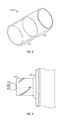
Shown in FIG. 3 is the light cover 110 which substantially encircles the light source 104 (FIG. 2). This light cover 110 may include a clear section 112 and a filtering section 114. The clear section 112 is designed to allow all wavelengths of light from the light source 104 to pass through the light cover 110, allowing the searchlight to be used in a normal operating mode. The filtering section 114 is positioned on a separate part of the light cover 110 and only allows selective wavelengths of light to pass through the cover 110. According to one embodiment, the filtering section 114 may include an infrared filter, preventing visible and ultraviolet light from passing through the light cover 110 while allowing infrared light to pass through.
As further shown in FIG. 3, the light cover 110 may be a substantially cylindrical cover, comprised of a transparent material to provide a clear portion 112. A filtering material may be applied to provide a filtering portion 114 of the light cover 110. The light cover 110 is shown as having a generally cylindrical shape with a circular cross section but it is contemplated that the light cover 110 may comprise a variety of cross sections, including but not limited to continuous or non-continuous curves, regular and irregular geometric figures, and symmetrical or non-symmetrical curves, including ellipses or other closed figures. Further, while the light cover 110 is shown as having a consistent cross section across its entire length, it is contemplated that the light filter may have a continuous or varied cross section along its length, including a narrowing, widening, or otherwise geometrically changing cross section.
The use of distinct clear and infrared-filtering sections on the light cover is merely exemplary, and other combinations may be utilized without departing from the scope of the disclosure. Other filters or shutters for limiting the wavelengths or amount of light that passes through the light cover 110 will be known to those having skill in the art, and may include some combination of a clear, colored, ultraviolet, infrared, or multiple-wavelength light filter. Further, the light cover 110 is not limited to two separate and distinct regions. It is contemplated that three or more regions, including gradual filtering from one region to the next, may be utilized in combination with the light cover 110, or that several filtered layers may be stacked to allow for varied filtering options.
In order to switch between the clear 112 and infrared 114 sections of the light cover 110, the light cover 110 must be moved relative to the bulb by means of an actuator 116 shown in FIGS. 4 and 5A-B, such as an electronic actuator. This actuator 116 positions the light cover 110 so that the preferred portion, whether it is the clear 112 or infrared-filtering 114 portion, substantially surrounds the light source 104.
As shown in FIG. 4, the actuator is generally positioned outside of the reflector 106 and is movable with the light source 104 relative to the reflector. This arrangement allows the filter and light source to move together to adjust the light output of the searchlight as the beam is narrowed or widened. This prevents light leakage from around either the clear section 112 or filtering section 114 of the light cover 110 when the light source 104 is moved, which may be undesirable depending on the use of the searchlight.
FIGS. 5A and 5B illustrate a side cutaway view of the reflector 100 showing the light cover 110 in a first (FIG. 5A) and second (FIG. 5B) position, thereby exposing the light source 104 to the clear 112 and filtering 114 sections of the cover 110.
As shown in FIG. 5A, the light cover 110 is in a first position whereby the clear section 112 of the light cover 110 surrounds the light source 104. The light source 104 may generally consist of an anode 118, a glass bulb 120, and a cathode 122 opposite the anode 118. To generate light, as is well known in the art, an electrical current is passed from the anode 118 to the cathode 122 and exciting the gas within the glass bulb 120. When excited, xenon gas creates a bright white light that radiates away from the gas and through the glass bulb 120. While white light produced from xenon is one embodiment, it is understood that other gas sources may be used to create other colors of light.
As further shown in FIG. 5A, light rays 124 are emitted from the glass bulb 120 and extend radially away from the bulb 120. The light rays 124 then pass through the light cover 110 and are reflected off of the reflector 106 (FIG. 2). The reflector 106 is generally shown to be a parabolic reflector which aligns light rays 124 to be substantially parallel as they pass through the cover 108. In the arrangement shown in FIG. 5A, the clear portion 112 of the light cover 110 is positioned about the light source 104, allowing light rays 124 of all wavelengths to pass through the light cover 110.
FIG. 5B shows the light cover 110 in a second position where the filtered portion 114 of the light cover 110 substantially covers the light source 104, or more particularly, the gas-filled light emitting glass bulb 120. As shown in this figure, light rays 124 are emitted from the xenon gas within the glass bulb 120 as described above. However, a layer of filtering material on the filtered portion 114 of the light cover 110 absorbs or reflects non-preferred wavelengths of light. In the example described, this filter allows only infrared light to pass through while reflecting or absorbing non-infrared light. Rays of infrared light 126 are then reflected from the reflector surface 106 and pass through the cover 108.
Shown in further detail in FIG. 6 is the actuator 116 which controls the position of light cover 110. This actuator 116 moves the light cover 110 from the first to second position so that rays of light 126 engage either the clear section 112 or filtering section 114 of the light cover 110. In the embodiment illustrated the actuator 116 includes a motor (not shown), inner sleeve 119 and outer sleeve 121. The outer sleeve 121 includes a spiral slot 125 that extends radially and axially about the outer sleeve 121. The inner sleeve 119 includes a straight slot 127 that extends only axially about the inner sleeve. As shown in FIGS. 5A-B, an anchor 123 is provided on the light cover 110 that extends through the spiral 125 and straight 127 slots. The slots 125, 127 are sized to approximately the same size as the anchor 123, and therefore movement of the anchor is constrained by the positions of the inner 119 and outer sleeves 121 to each other. According to the embodiment illustrated, the motor may be connected alternatively to the inner 119 or outer 121 sleeves to rotate one relative to the other when the motor is engaged. Because the slots 125, 127 constrain the position of the anchor 123, as the outer sleeve 121 is rotated relative to the inner sleeve 119, the anchor traverses the spiral slot 125 radially while traversing the straight slot 127 axially. These two slots therefore control the position of the light cover 110 between the positions shown in FIGS. 5A-B. Other methods of adjusting the position of the lamp cover 110 are contemplated in the present disclosure and will be appreciated by those having skill in the art. These methods may include a worm gear, screw, belt, cam, or other method of translating the light cover 110 that may be apparent to those having skill in the art.
In the embodiments illustrated, reflector 106 and actuator 116 are coupled to move with one another. This coupling allows adjustment of the light source 104 relative to the reflector 106 without adjusting the position of the reflector 106 relative to the light cover 110. This is to maintain the integrity of the light seal 128 (FIGS. 5A and 5B) around the light cover 110, preventing light of unwanted wavelengths from leaking out, which may compromise the purpose of utilizing an infrared filter.
FIG. 7A shows a perspective view of an alternative embodiment of the light cover 110. The light cover 110 preferably includes a clear portion 112 and a filtered portion 114 adjacent to one another such that the light cover 110 may selectively filter a light source 104 (FIG. 2). In this embodiment, the light cover 110 may be constructed from a number of multiple flat segments 132. An exemplar of these multiple flat segments 132 is shown in FIG. 7B. Each segment 132 may include a clear section 112 and a filtering section 114 as described above, and according to the embodiment illustrated, all of the flat segments may be substantially identical. The segments 132 may be constructed, for example, of flat segments of quartz glass with a portion having an infrared sapphire coating or coated using another existing infrared filter coating. However, it should be understood by those having skill in the art that the shape, size, and material of the segments 132 may vary without departing from the scope of the disclosure.
Also disclosed in this application is a novel method for switching a searchlight 100 between infrared and white light. This method is described with reference to the above-described apparatus. This method includes the steps of providing a searchlight 100 as described, generally including a housing 102, light source 104, reflector 106, cover 108 and light cover 110. The light cover 110 is positioned about the light source 104 as described above and is movable between first and second positions. In each of the first and second positions either of a clear 112 or filtered section 114, respectively, are positioned to capture light emitted from the light source 104. In ordinary operation, the light source 104 projects light through either the clear section 112 of the light cover 110. In order to adjust the lamp from projecting clear light to infrared light, an actuator 116 may be engaged to move the light cover 110 to the second position, thereby surrounding the light source 104 with the filtered section 114 of the light cover 110. Movement of the light cover 110 may by means of electronic, manual, mechanical, hydraulic, or other known control system.
The above description is intended to demonstrate several embodiments of the disclosed apparatus and is not intended to limit the scope of the invention. Any limitations will appear in the claims as allowed.

Claims (20)

What is claimed is:
1. A method of converting the light output from a searchlight from a first light profile to a second light profile, the method comprising the steps of:
providing a searchlight having a reflector and light source;
providing a light cover about the light source, the light cover being substantially cylindrical;
providing the light cover with a first portion constructed of a transparent material whereby light from the light source through the transparent material of the first portion conforms to the first light profile;
providing the light cover with a second portion constructed of a light filtering material whereby light from the light source through the lamp cover conforms to the second light profile;
providing an actuator configured to move the light cover from a first position relative to the light source and reflector, whereby the light source shines through the first portion, to a second position relative to the light source and reflector different from the first position, whereby the lamp shines through the second portion; and
providing a light seal around the light cover, thereby preventing light of unwanted wavelengths from leaking out from the lamp cover.
2. The method of claim 1, whereby said first light profile is white light.
3. The method of claim 1, whereby said second light profile is infrared light.
4. The method of claim 1, whereby said light source consists of a xenon lamp.
5. The method of claim 1, whereby said reflector comprises a parabolic reflector.
6. The method of claim 1, whereby said light cover comprises a plurality of flat segments.
7. The method of claim 6, whereby a portion of each of said flat segments includes an infrared filter coating.
8. An apparatus for providing filtered or unfiltered light, the apparatus comprising:
a reflector having an interior and an edge;
a lamp positioned within the interior of the reflector surface;
a light cover concentric about the lamp, the light cover including a first section and a second section, wherein the first section of the lamp is constructed of a transparent material, and wherein light filtering characteristics of the first and second sections are different;
an actuator configured to move the light cover from a first position relative to the light source and reflector to a second position relative to the light source and reflector different from the first position, wherein when the lamp cover is in the first position light from the lamp is projected through the transparent material of the first section and wherein when the lamp cover is in the second position light from the lamp is projected through the second section; and
the light cover including a light seal configured to prevent light of unwanted wavelengths from leaking out from the lamp cover.
9. The apparatus of claim 8, wherein said first section is clear to allow said searchlight to be used in a normal operating mode.
10. The apparatus of claim 9, wherein said second section is an infrared filter that prevents visible and ultraviolet light from passing through.
11. The apparatus of claim 10, wherein said filter comprises a coating applied to said lamp cover.
12. The apparatus of claim 8, wherein said actuator is electronically activated.
13. The apparatus of claim 8, wherein said actuator is fixed relative to said lamp.
14. The apparatus of claim 8, wherein said lamp is movable relative to said reflector surface.
15. The apparatus of claim 8, wherein said reflector includes a surface comprising a metal form with a highly reflective coating applied to said interior.
16. A method of manufacturing a searchlight system, the method comprising:
providing a reflector;
providing a light source within the reflector;
providing a plurality of optically transparent flat segments;
applying a filtering coating to a portion of the flat segments to create a filtered section and an unfiltered section, wherein the unfiltered section is constructed of a transparent material;
arranging the flat segments into a substantially cylindrical light cover, and positioning the light cover over the light source within the reflector;
providing an actuator;
attaching the actuator to the light cover in a manner such that the actuator may move the light cover relative to the light source and reflector to expose the light source to either the filtered section in a first position or the unfiltered section in a second position different from the first position; and
providing a light seal around the light cover, thereby preventing light of unwanted wavelengths from leaking out from the lamp cover.
17. The method of claim 16, wherein said plurality of flat segments comprise quartz glass or sapphire.
18. The method of claim 17, wherein said filtering coating comprises an infrared coating.
19. The method of claim 18, wherein said infrared coating is applied to half of the flat segments.
20. The method of claim 19, wherein said flat segments are arranged to provide a first unfiltered section and a second filtered section of said cover, said unfiltered section being distal from said filtered section.
US13/206,208 2011-08-09 2011-08-09 Internal covert IR filter for searchlight systems Active 2032-01-15 US8905587B1 (en)

Priority Applications (1)

Application Number Priority Date Filing Date Title
US13/206,208 US8905587B1 (en) 2011-08-09 2011-08-09 Internal covert IR filter for searchlight systems

Applications Claiming Priority (1)

Application Number Priority Date Filing Date Title
US13/206,208 US8905587B1 (en) 2011-08-09 2011-08-09 Internal covert IR filter for searchlight systems

Publications (1)

Publication Number Publication Date
US8905587B1 true US8905587B1 (en) 2014-12-09

Family

ID=52001591

Family Applications (1)

Application Number Title Priority Date Filing Date
US13/206,208 Active 2032-01-15 US8905587B1 (en) 2011-08-09 2011-08-09 Internal covert IR filter for searchlight systems

Country Status (1)

Country Link
US (1) US8905587B1 (en)

Cited By (18)

* Cited by examiner, † Cited by third party
Publication number Priority date Publication date Assignee Title
US20170167696A1 (en) * 2015-12-15 2017-06-15 Wangs Alliance Corporation Led lighting methods and apparatus
WO2017185485A1 (en) * 2016-04-29 2017-11-02 中兴通讯股份有限公司 Projector processing method and device, and projector camera
US10040575B2 (en) 2016-07-15 2018-08-07 Goodrich Lighting Systems, Inc. Dual mode aircraft light assembly
US10516216B2 (en) 2018-01-12 2019-12-24 Eagle Technology, Llc Deployable reflector antenna system
US10707552B2 (en) 2018-08-21 2020-07-07 Eagle Technology, Llc Folded rib truss structure for reflector antenna with zero over stretch
US10941924B2 (en) 2015-12-15 2021-03-09 Wangs Alliance Corporation LED lighting methods and apparatus
US11162651B2 (en) 2019-12-31 2021-11-02 Jiangsu Sur Lighting Co., Ltd Lamp module group
CN114151763A (en) * 2021-09-30 2022-03-08 兰州万里航空机电有限责任公司 Rear navigation light with lower hemisphere plated and filtered infrared film
US11421837B2 (en) 2020-04-23 2022-08-23 Jiangsu Sur Lighting Co., Ltd. Spotlight structure
US11598517B2 (en) 2019-12-31 2023-03-07 Lumien Enterprise, Inc. Electronic module group
US11686459B2 (en) 2015-12-15 2023-06-27 Wangs Alliance Corporation LED lighting methods and apparatus
US11802682B1 (en) 2022-08-29 2023-10-31 Wangs Alliance Corporation Modular articulating lighting
US11812525B2 (en) 2017-06-27 2023-11-07 Wangs Alliance Corporation Methods and apparatus for controlling the current supplied to light emitting diodes
US11812532B2 (en) 2021-05-27 2023-11-07 Wangs Alliance Corporation Multiplexed segmented lighting lamina
US11829140B2 (en) 2021-02-17 2023-11-28 Honeywell International Inc. Methods and systems for searchlight control for aerial vehicles
US12230950B2 (en) 2021-07-29 2025-02-18 Lumien Enterprise, Inc. Junction box
US12281783B2 (en) 2019-12-31 2025-04-22 Lumien Enterprise, Inc. Electronic module group
US12513799B2 (en) 2023-07-25 2025-12-30 Wangs Alliance Corporation Off-fixture lighting control circuit

Citations (15)

* Cited by examiner, † Cited by third party
Publication number Priority date Publication date Assignee Title
US5695272A (en) 1994-05-27 1997-12-09 Grimes Aerospace Company Search light for aircraft and other vehicles
US5735594A (en) * 1996-12-30 1998-04-07 Own; James Flashlight
US5882107A (en) 1995-11-16 1999-03-16 Vari-Lite, Inc. Compact luminaire system
US6068385A (en) 1998-03-18 2000-05-30 Hsieh; Jordan Durable lamp having air cooled moveable bulb
US20010019482A1 (en) * 2000-02-15 2001-09-06 Shoji Kobayashi Infrared-ray radiating lamp for automobile
US20020154513A1 (en) * 2001-04-24 2002-10-24 Koito Manufacturing Co., Ltd. Infrared light irradiation lamp for automobile
US6644840B2 (en) * 2001-04-24 2003-11-11 Koito Manufacturing Co., Ltd. Infrared irradiation lamp for automobile
WO2004023036A1 (en) 2002-09-09 2004-03-18 Vector Scientific Pty Ltd A spotlight
US20050052869A1 (en) * 2001-06-15 2005-03-10 Brenner Paul E. Anti-collision light for aircraft
US6962423B2 (en) 2001-11-06 2005-11-08 Honeywell International Inc. Multi-mode searchlight
US7021804B2 (en) * 2003-08-13 2006-04-04 Guide Corporation Lamp assembly with multi-stage reflector
US7033051B2 (en) * 2003-06-11 2006-04-25 Hyundai Motor Company Infrared ray irradiation apparatus for night vision system
US7331692B2 (en) 2002-05-06 2008-02-19 Bruno Baiardi Light beam projector with filter set rotating on its own axis
US7518133B2 (en) 2006-10-30 2009-04-14 Honeywell International Inc. Integrated searchlight lighthead
US8292479B2 (en) * 2008-09-08 2012-10-23 Koito Manufacturing Co., Ltd. Vehicular infrared irradiation lamp

Patent Citations (15)

* Cited by examiner, † Cited by third party
Publication number Priority date Publication date Assignee Title
US5695272A (en) 1994-05-27 1997-12-09 Grimes Aerospace Company Search light for aircraft and other vehicles
US5882107A (en) 1995-11-16 1999-03-16 Vari-Lite, Inc. Compact luminaire system
US5735594A (en) * 1996-12-30 1998-04-07 Own; James Flashlight
US6068385A (en) 1998-03-18 2000-05-30 Hsieh; Jordan Durable lamp having air cooled moveable bulb
US20010019482A1 (en) * 2000-02-15 2001-09-06 Shoji Kobayashi Infrared-ray radiating lamp for automobile
US6644840B2 (en) * 2001-04-24 2003-11-11 Koito Manufacturing Co., Ltd. Infrared irradiation lamp for automobile
US20020154513A1 (en) * 2001-04-24 2002-10-24 Koito Manufacturing Co., Ltd. Infrared light irradiation lamp for automobile
US20050052869A1 (en) * 2001-06-15 2005-03-10 Brenner Paul E. Anti-collision light for aircraft
US6962423B2 (en) 2001-11-06 2005-11-08 Honeywell International Inc. Multi-mode searchlight
US7331692B2 (en) 2002-05-06 2008-02-19 Bruno Baiardi Light beam projector with filter set rotating on its own axis
WO2004023036A1 (en) 2002-09-09 2004-03-18 Vector Scientific Pty Ltd A spotlight
US7033051B2 (en) * 2003-06-11 2006-04-25 Hyundai Motor Company Infrared ray irradiation apparatus for night vision system
US7021804B2 (en) * 2003-08-13 2006-04-04 Guide Corporation Lamp assembly with multi-stage reflector
US7518133B2 (en) 2006-10-30 2009-04-14 Honeywell International Inc. Integrated searchlight lighthead
US8292479B2 (en) * 2008-09-08 2012-10-23 Koito Manufacturing Co., Ltd. Vehicular infrared irradiation lamp

Non-Patent Citations (11)

* Cited by examiner, † Cited by third party
Title
Press Release, "Revue Thommen Displays the HSL-1600 Helicopter Searchlight at ALEA in New Orleans," http://www.rotorpad.com/manufacturers/revue-thommen-displays-the-hsl-1600-helicopter-searchliqht-at-alea-in-new-orleans.html (Jul. 20, 2011).
Press Release, "Revue Thommen displays the HSL-1600 helicopter searchlight," http://www.shephard.co.uk/news/rotorhub/revue-thommen-displays-the-hsl-1600-helicopter-searchlight/8146/ (Jan. 20, 2011).
Product literature for "Trakkabeam®-M500," by Trakka Corp. Pty. Ltd., http://www.trakkacorp.com/tc/pdf/M500Brochure2006.pdf (2009).
Product literature for "Trakkabeam®—M500," by Trakka Corp. Pty. Ltd., http://www.trakkacorp.com/tc/pdf/M500Brochure2006.pdf (2009).
Product literature for "Trakkabeam®-M800," by Trakka Corp. Pty. Ltd., http://www:trakkacorp.com/tc/pdf/M800Brochure2006 (2009).
Product literature for "Trakkabeam®—M800," by Trakka Corp. Pty. Ltd., http://www:trakkacorp.com/tc/pdf/M800Brochure2006 (2009).
Product literaure for Trakkabeam® A800, by Trakka Corp.Pty. Ltd., http://www.trakkacorp.com/tc/pdf/a800brochure2006.pdf (2009).
Product literaure for Trakkabeam® A800, by Trakka Corp.Pty. Ltd., http://www.trakkacorp.com/tc/pdf/A800Brochure2010-letter.pdf.
Product literaure for Trakkabeam® A800, by Trakka Corp.Pty. Ltd., http://www.trakkacorp.com/tc/pdf/A800Brochure2010—letter.pdf.
Revue Thommen AG Product Presentation: Thommen HSL 1600 (Apr. 14, 2011).
Web page featuring "HeliLight 1®," by Universal Searchlights, LLC, http://www.universalsearchlights.com/helilight.html (2009).

Cited By (41)

* Cited by examiner, † Cited by third party
Publication number Priority date Publication date Assignee Title
US11940135B2 (en) 2015-12-15 2024-03-26 Wangs Alliance Corporation LED lighting methods and apparatus
US10598358B2 (en) 2015-12-15 2020-03-24 Wangs Alliance Corporation LED lighting methods and apparatus
US11686459B2 (en) 2015-12-15 2023-06-27 Wangs Alliance Corporation LED lighting methods and apparatus
US10190757B2 (en) 2015-12-15 2019-01-29 Wangs Alliance Corporation LED lighting methods and apparatus
US10208935B2 (en) * 2015-12-15 2019-02-19 Wangs Alliance Corporation LED lighting apparatus with adjustable beam angle lens
US11892150B2 (en) 2015-12-15 2024-02-06 Wangs Alliance Corporation LED lighting methods and apparatus
US10323832B2 (en) 2015-12-15 2019-06-18 Wangs Alliance Corporation LED lighting methods and apparatus
US10330294B2 (en) 2015-12-15 2019-06-25 Wangs Alliance Corporation LED lighting methods and apparatus
US10465888B1 (en) 2015-12-15 2019-11-05 Wangs Alliance Corporation LED lighting methods and apparatus
US11408597B2 (en) 2015-12-15 2022-08-09 Wangs Alliance Corporation LED lighting methods and apparatus
US10571101B2 (en) 2015-12-15 2020-02-25 Wangs Alliance Corporation LED lighting methods and apparatus
US11719422B2 (en) 2015-12-15 2023-08-08 Wangs Alliance Corporation LED lighting methods and apparatus
US20170167696A1 (en) * 2015-12-15 2017-06-15 Wangs Alliance Corporation Led lighting methods and apparatus
US10920971B2 (en) 2015-12-15 2021-02-16 Wangs Alliance Corporation LED lighting methods and apparatus
US10928045B2 (en) 2015-12-15 2021-02-23 Wangs Alliance Corporation LED lighting methods and apparatus
US10941924B2 (en) 2015-12-15 2021-03-09 Wangs Alliance Corporation LED lighting methods and apparatus
US10962209B2 (en) 2015-12-15 2021-03-30 Wangs Alliance Corporation LED lighting methods and apparatus
US12535200B2 (en) 2015-12-15 2026-01-27 Wangs Alliance Corporation LED lighting methods and apparatus
WO2017185485A1 (en) * 2016-04-29 2017-11-02 中兴通讯股份有限公司 Projector processing method and device, and projector camera
US10301040B2 (en) 2016-07-15 2019-05-28 Goodrich Lighting Systems, Inc. Dual mode aircraft light assembly
US10040575B2 (en) 2016-07-15 2018-08-07 Goodrich Lighting Systems, Inc. Dual mode aircraft light assembly
US11812525B2 (en) 2017-06-27 2023-11-07 Wangs Alliance Corporation Methods and apparatus for controlling the current supplied to light emitting diodes
US10516216B2 (en) 2018-01-12 2019-12-24 Eagle Technology, Llc Deployable reflector antenna system
US10707552B2 (en) 2018-08-21 2020-07-07 Eagle Technology, Llc Folded rib truss structure for reflector antenna with zero over stretch
US11466821B2 (en) 2019-12-31 2022-10-11 Jiangsu Sur Lighting Co., Ltd. Lamp module group
US12281783B2 (en) 2019-12-31 2025-04-22 Lumien Enterprise, Inc. Electronic module group
US11162651B2 (en) 2019-12-31 2021-11-02 Jiangsu Sur Lighting Co., Ltd Lamp module group
US12435846B2 (en) 2019-12-31 2025-10-07 Lumien Enterprise, Inc. Lamp module group
US12270535B2 (en) 2019-12-31 2025-04-08 Lumien Inc. Electronic module group
US11598517B2 (en) 2019-12-31 2023-03-07 Lumien Enterprise, Inc. Electronic module group
US12018828B2 (en) 2019-12-31 2024-06-25 Lumien Enterprise, Inc. Electronic module group
US11959601B2 (en) 2019-12-31 2024-04-16 Lumien Enterprise, Inc. Lamp module group
US11421837B2 (en) 2020-04-23 2022-08-23 Jiangsu Sur Lighting Co., Ltd. Spotlight structure
US11829140B2 (en) 2021-02-17 2023-11-28 Honeywell International Inc. Methods and systems for searchlight control for aerial vehicles
US12207369B2 (en) 2021-05-27 2025-01-21 Wangs Alliance Corporation Multiplexed segmented lighting lamina
US11812532B2 (en) 2021-05-27 2023-11-07 Wangs Alliance Corporation Multiplexed segmented lighting lamina
US12230950B2 (en) 2021-07-29 2025-02-18 Lumien Enterprise, Inc. Junction box
CN114151763A (en) * 2021-09-30 2022-03-08 兰州万里航空机电有限责任公司 Rear navigation light with lower hemisphere plated and filtered infrared film
CN114151763B (en) * 2021-09-30 2024-07-05 兰州万里航空机电有限责任公司 Rear navigation lamp with lower hemisphere coated with infrared filter film
US11802682B1 (en) 2022-08-29 2023-10-31 Wangs Alliance Corporation Modular articulating lighting
US12513799B2 (en) 2023-07-25 2025-12-30 Wangs Alliance Corporation Off-fixture lighting control circuit

Similar Documents

Publication Publication Date Title
US8905587B1 (en) Internal covert IR filter for searchlight systems
KR101845846B1 (en) Lighting system with daytime running light
JP5815995B2 (en) Optical unit for vehicular lamp
US9243768B2 (en) Light source for headlight and headlight
US9915403B2 (en) Vehicle lamp
JP2001067909A (en) Projector type head lamp
KR101344381B1 (en) Colored headlamp
JP6445441B2 (en) Optical unit
CA2530570C (en) Colored headlamp
US9695990B2 (en) Arrangement for light emission
JP2012238477A (en) Lamp unit
EP3063460B1 (en) Luminaire with selectable emission pattern
US9429300B2 (en) Method and apparatus for selective filtering of an illumination device
TWI565606B (en) Motor vehicle lighting device
US7021804B2 (en) Lamp assembly with multi-stage reflector
RU2438067C2 (en) Multi-functional front headlight on light diodes
US7033054B2 (en) Lamp assembly with peripheral auxiliary function
JP5620872B2 (en) LED light emitting device
US20080266891A1 (en) Lamp for a Vehicle Headlight Featuring a Dimmed Function
KR101614849B1 (en) Structure of high and low beams head light
RU2798449C9 (en) Landing and search lamp
US4833577A (en) Light source in a subdivided arrangement
CN101832501A (en) Vehicle headlamp with LED light source
RU2798449C1 (en) Landing and search lamp
RU82178U1 (en) LIGHT SOURCE (OPTIONS), VEHICLE HEADLIGHT (OPTIONS) AND OPTICAL SYSTEM OF THE LIGHT SOURCE (OPTIONS)

Legal Events

Date Code Title Description
AS Assignment

Owner name: THE BOEING COMPANY, ILLINOIS

Free format text: ASSIGNMENT OF ASSIGNORS INTEREST;ASSIGNOR:BOUCKAERT, ANTON M.;REEL/FRAME:026732/0727

Effective date: 20110804

FEPP Fee payment procedure

Free format text: PAYOR NUMBER ASSIGNED (ORIGINAL EVENT CODE: ASPN); ENTITY STATUS OF PATENT OWNER: LARGE ENTITY

STCF Information on status: patent grant

Free format text: PATENTED CASE

MAFP Maintenance fee payment

Free format text: PAYMENT OF MAINTENANCE FEE, 4TH YEAR, LARGE ENTITY (ORIGINAL EVENT CODE: M1551)

Year of fee payment: 4

MAFP Maintenance fee payment

Free format text: PAYMENT OF MAINTENANCE FEE, 8TH YEAR, LARGE ENTITY (ORIGINAL EVENT CODE: M1552); ENTITY STATUS OF PATENT OWNER: LARGE ENTITY

Year of fee payment: 8