US8899190B2 - Temperature dependent flow control for combustion engine piston squirters - Google Patents
Temperature dependent flow control for combustion engine piston squirters Download PDFInfo
- Publication number
- US8899190B2 US8899190B2 US13/871,113 US201313871113A US8899190B2 US 8899190 B2 US8899190 B2 US 8899190B2 US 201313871113 A US201313871113 A US 201313871113A US 8899190 B2 US8899190 B2 US 8899190B2
- Authority
- US
- United States
- Prior art keywords
- piston
- engine
- oil
- valve element
- flow
- Prior art date
- Legal status (The legal status is an assumption and is not a legal conclusion. Google has not performed a legal analysis and makes no representation as to the accuracy of the status listed.)
- Expired - Fee Related, expires
Links
Images


Classifications
-
- F—MECHANICAL ENGINEERING; LIGHTING; HEATING; WEAPONS; BLASTING
- F01—MACHINES OR ENGINES IN GENERAL; ENGINE PLANTS IN GENERAL; STEAM ENGINES
- F01M—LUBRICATING OF MACHINES OR ENGINES IN GENERAL; LUBRICATING INTERNAL COMBUSTION ENGINES; CRANKCASE VENTILATING
- F01M1/00—Pressure lubrication
- F01M1/16—Controlling lubricant pressure or quantity
-
- F—MECHANICAL ENGINEERING; LIGHTING; HEATING; WEAPONS; BLASTING
- F01—MACHINES OR ENGINES IN GENERAL; ENGINE PLANTS IN GENERAL; STEAM ENGINES
- F01M—LUBRICATING OF MACHINES OR ENGINES IN GENERAL; LUBRICATING INTERNAL COMBUSTION ENGINES; CRANKCASE VENTILATING
- F01M1/00—Pressure lubrication
- F01M1/08—Lubricating systems characterised by the provision therein of lubricant jetting means
-
- F—MECHANICAL ENGINEERING; LIGHTING; HEATING; WEAPONS; BLASTING
- F16—ENGINEERING ELEMENTS AND UNITS; GENERAL MEASURES FOR PRODUCING AND MAINTAINING EFFECTIVE FUNCTIONING OF MACHINES OR INSTALLATIONS; THERMAL INSULATION IN GENERAL
- F16K—VALVES; TAPS; COCKS; ACTUATING-FLOATS; DEVICES FOR VENTING OR AERATING
- F16K31/00—Actuating devices; Operating means; Releasing devices
- F16K31/002—Actuating devices; Operating means; Releasing devices actuated by temperature variation
-
- Y—GENERAL TAGGING OF NEW TECHNOLOGICAL DEVELOPMENTS; GENERAL TAGGING OF CROSS-SECTIONAL TECHNOLOGIES SPANNING OVER SEVERAL SECTIONS OF THE IPC; TECHNICAL SUBJECTS COVERED BY FORMER USPC CROSS-REFERENCE ART COLLECTIONS [XRACs] AND DIGESTS
- Y10—TECHNICAL SUBJECTS COVERED BY FORMER USPC
- Y10T—TECHNICAL SUBJECTS COVERED BY FORMER US CLASSIFICATION
- Y10T137/00—Fluid handling
- Y10T137/7722—Line condition change responsive valves
- Y10T137/7737—Thermal responsive
Definitions
- the present invention relates generally to a system for controlling the flow of oil through one or more oil squirters according to the temperature of the oil.
- IC engines such as those used in motor vehicles, typically generate heat energy as a by-product of generating power. Generally, such engines are also cooled in order to maintain their operating temperature in a particular range and ensure the engine's efficient and reliable performance for propelling the subject motor vehicle.
- IC engines are cooled by a circulating fluid, such as a specially formulated chemical compound mixed with water. Additionally, such engines are lubricated and cooled by oils that are generally derived from petroleum-based and non-petroleum synthesized chemical compounds. Under extreme operating conditions, IC engines generate elevated amounts of heat energy within their combustion chambers. If heat is generated faster than it can be removed using existing cooling systems, it may affect the performance and/or reliability of the engine.
- a circulating fluid such as a specially formulated chemical compound mixed with water.
- oils that are generally derived from petroleum-based and non-petroleum synthesized chemical compounds.
- An engine assembly includes an engine block that defines a cylinder bore, and a reciprocating piston disposed in the cylinder bore.
- the piston has a first side and a second side, where the first side cooperates with the engine block to partially define a combustion chamber, and the second side is opposite the first side.
- a piston squirter is disposed adjacent to the second side of the piston and configured to expel a received flow of engine oil onto the piston to cool and lubricate the piston and bore.
- a thermal fluid valve is disposed in fluid communication with the piston squirter and is configured to selectively restrict the flow of engine oil to the piston squirter in response to a temperature of the engine oil.
- the thermal fluid valve may include an inlet, an outlet, and a bi-metallic valve element.
- the bi-metallic valve element is transitionable between an open state and a closed state in response to a temperature of the bi-metallic valve element, and the thermal fluid valve is configured to restrict the flow of engine oil to the piston squirter when the bi-metallic valve element is in a closed state.
- the thermal fluid valve is configured to permit the flow of engine oil to the piston squirter when the bi-metallic valve element is in an open state.
- engine oil is configured to directly contact the bi-metallic valve element, such that the temperature of the bi-metallic valve element is approximately equal to the temperature of the engine oil (i.e., via heat transfer by conduction).
- the bi-metallic valve element generally includes a first metal layer fused to a second metal layer, where the first metal layer has a coefficient of thermal expansion that is different than a coefficient of thermal expansion of the second metal layer. In this manner, the bi-metallic valve element may deform in response to a temperature change.
- the thermal fluid valve may further include a housing that defines the inlet and the outlet, as well as an internal volume in fluid communication with the inlet and the outlet.
- the bi-metallic valve element may then be disposed within the internal volume, between the inlet and the outlet.
- the housing may include a control surface abutting and partially defining the internal volume, and adjacent to the outlet.
- the control surface may define an annular land circumferentially disposed about the outlet, wherein the bi-metallic valve element is configured to contact and seal against the annular land when in a closed state.
- the control surface of the valve housing may further define a flow channel extending radially outward from the annular land, and extending away from the bi-metallic valve element. In this manner, engine oil may flow around an edge of the bi-metallic valve element via the flow channel.
- the engine assembly may further include an oil reservoir and an oil pump, with the oil pump being in fluid communication with the oil reservoir and with the thermal fluid valve.
- the oil pump may be configured to provide the flow of oil from the oil reservoir to the piston squirter via the thermal fluid valve.
- the engine assembly may further include a rotatable crankshaft.
- the oil pump may then be further configured to provide a second flow of oil to the rotatable crankshaft.
- FIG. 1 is a schematic partial cross-sectional illustration of an engine assembly including a piston squirter configured to spray oil directly onto a piston.
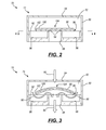
- FIG. 2 is a schematic cross-sectional side view of a thermal fluid valve in a closed state.
- FIG. 3 is a schematic cross-sectional side view of the thermal fluid valve of FIG. 2 in an open state.
- FIG. 4 is a schematic cross-sectional top view of the thermal fluid valve of FIG. 2 , taken along line 4 - 4 .
- FIG. 1 schematically illustrates an engine assembly 10 that may be used to convert a chemical potential of a combustible fuel into a rotational mechanical output.
- the engine assembly 10 may include an oil pan 12 , an engine block 14 , a cylinder head 16 , and a cylinder head cover 18 that are generally disposed in a stacked arrangement.
- the engine block 14 may define a plurality of cylinder bores 20 (one of which is shown), with each cylinder bore 20 having a reciprocating piston 22 disposed therein.
- the plurality of cylinder bores 20 may be arranged in any suitable manner, such as, without limitation, a V-engine arrangement, an inline engine arrangement, and a horizontally opposed engine arrangement, as well as using both overhead cam and cam-in-block configurations.
- the cylinder head 16 For each respective cylinder bore 20 , the cylinder head 16 , engine block 14 , and reciprocating piston 22 may cooperate to define a combustion chamber 24 on a first side 26 of the piston 22 .
- the cylinder head 16 may provide one or more intake passages 28 and exhaust passages 30 in selective fluid communication with each respective combustion chamber 24 .
- the intake passage 44 may be used to deliver fresh air to the combustion chamber 24 (e.g., from an intake manifold), where it may mix with an injected aerosol fuel.
- the exhaust passage 30 Following combustion of the air/fuel mixture (such as when ignited by a spark from a spark plug 32 ), the exhaust passage 30 may carry exhaust gasses out of the combustion chamber 24 .
- the engine assembly 10 may include a lubrication system 40 , which may include an oil pump 42 in fluid communication with an oil reservoir 44 .
- the oil pump 42 may be a mechanical pump that may be selectively drivable by a rotational output of the engine.
- the oil pump 42 may be an electrically operated pump that may be controllably operated by an electric power source (not shown).
- the oil reservoir 44 may be partially defined by the oil pan 12 and may contain an engine oil 46 , such as a petroleum-based or synthetic-based oil.
- the oil pump 42 may draw engine oil 46 from the oil reservoir 44 , pressurize it, and supply it to various moving components within the engine 10 to lubricate and/or cool those components.
- the oil pump 42 may provide oil 46 via a first supply line 48 to a crankshaft 50 , which may constantly rotate with the operation of the engine.
- the oil pump 42 may provide oil 46 to one or more camshafts 52 via a second supply line 54 .
- the oil pump 42 may further supply oil 46 to one or more piston squirters 56 , where the oil may be operative to directly lubricate and/or cool the piston 22 .
- Each piston squirter 56 may include a nozzled portion 58 that may be configured to spray pressurized oil 60 onto an underside (i.e., second side 62 ) of the piston 22 and/or onto the wall of the engine bore 20 . In this manner, the piston/bore interface may be actively lubricated, rather than merely relying on passive oil atomization/splash from the oil reservoir 44 and/or crankshaft 50 .
- the piston squirter 56 may extend from a portion of the engine block 14 , and the nozzled portion 58 may be aimed such that the expelled oil 60 directly contacts the piston 22 when the piston 22 is in a bottom dead center position, and directly contacts the cylinder bore 20 and/or piston 22 when the piston 22 is in a top dead center position.
- the piston squirter may include an orifice directly formed into the cylinder bore, or into another adjacent component.
- the primary heat source within the engine assembly 10 is the combustion chamber, where fuel is continuously burned.
- the piston 22 and cylinder bore 20 may accumulate thermal energy faster than it can be dissipated using traditional engine cooling systems. This heat accumulation problem is further accentuated in high-compression engines, which force an increased amount of air/fuel into the combustion chamber with every cycle.
- piston squirters 56 may be operative to lubricate the piston 22 /bore 20 , during periods of extreme/prolonged use, they may be primarily useful in cooling the piston 22 /bore 20 by bathing the components in the (comparatively cooler) engine oil 46 . During periods of lighter use, however, the use of piston squirters 56 may be less beneficial, with any marginal cooling and/or lubrication benefits being generally offset by parasitic efficiency losses attributable to the increased oil flow/pumping. Likewise, in certain circumstances, such as low-temperature cold-engine starts, the cooling effect may even be undesirable if the goal is to actively warm the engine to an ideal operating temperature.
- the lubrication system 40 may further include a thermal fluid valve 70 that may be configured to automatically open as the temperature engine oil 46 increases above a critical temperature (i.e. suggesting the engine is at or above a temperature where active piston cooling is desirable).
- FIGS. 2 , 3 , and 4 illustrate one embodiment of a thermal fluid valve 70 that may be used in the above mentioned lubrication system 40 . As shown, FIG. 2 schematically illustrates a cross-sectional side view of the valve 70 in a closed state 72 , FIG. 3 schematically illustrates a cross-sectional side view of the valve 70 in an open state 74 , and FIG. 4 schematically illustrates a top view of the valve 70 provided in FIGS. 2 and 3 .
- the thermal fluid valve 70 may be a mechanical apparatus that may automatically transition between a closed state 72 and an open state 74 in response to a change in operating temperature, and without external actuation (e.g., electronic control signals).
- the thermal fluid valve 70 may include a housing 80 that defines an internal volume 82 as well as an inlet 84 and an outlet 86 on opposing sides of the internal volume 82 .
- the thermal fluid valve 70 may include a bi-metallic valve element 88 disposed within the housing 80 .
- the bi-metallic valve element 88 may be fluidly disposed between the inlet 84 and the outlet 86 , and may be configured to selectively obstruct a fluid flow 90 from the inlet 84 to the outlet 86 .
- the inlet may be coupled to and may receive oil 46 from the oil pump 42
- the outlet may be coupled to and may provide oil 46 to the piston squirters 56 .
- the bi-metallic valve element 88 when in a closed state 72 , the bi-metallic valve element 88 may be substantially undeformed, and may be forced against a control surface 92 adjacent the outlet 86 by the fluid pressure differential between the pump oil pressure and the crankcase gas pressure. In this state, the bi-metallic valve element 88 may substantially obstruct the outlet 86 and prevent fluid from freely flowing between the inlet 84 and the one or more piston squirters 56 .
- FIG. 4 more clearly illustrates the control surface 92 , with an approximate placement of the bi-metallic valve element 88 provided in phantom.
- the control surface 92 defines an annular land 94 circumferentially disposed about the outlet 86 .
- the control surface 92 may further define one or more flow channels 96 that extend radially outward from the annular land 94 .
- Each flow channel 96 may extend away from the bi-metallic valve element 88 , and may only be partially covered by the bi-metallic valve element 88 . In this manner, the flow channels 96 may allow physical separation between a portion of an outer edge 98 of the bi-metallic valve element 88 and the housing 82 .
- the bi-metallic valve element 88 may be comprised of two dissimilar metals or metal alloys (e.g., a first metal 100 and a second metal 102 ) that are fused together.
- the first and second metals 100 , 102 may be selected according to their respective rates of thermal expansion, together with the desired engine operating temperature.
- the first metal 100 i.e., more adjacent to the inlet 54
- the second metal 102 may expand at a greater rate than the second metal 102 .
- This difference in the expansion rates will cause the center 104 of the bi-metallic valve element 88 to bow away from the annular land 94 , as shown in FIG. 3 .
- oil 46 may flow 90 from the inlet 84 into the volume 82 , between the annular land 94 and bi-metallic valve element 88 , and out of the outlet 86 .
- the separation may increase, causing more oil 46 to flow to the piston squirters 56 to cool the pistons 22 and bores 20 .
- the thermal fluid valve 70 may be disposed on an interior surface of the engine block 14 and/or may be integrated within the piston squirters 56 . In this manner, the relationship between piston/bore temperature and oil flow may be more direct.
- FIG. 1 illustrates the oil pump 42 and supply lines 48 , 54 as external to the engine assembly 10
- the pump may be disposed within the engine block 14 /oil pan 12
- the various supply lines may include one or more bores, conduits, or other such flow paths provided within the walls of the engine assembly 10 .
- the present thermal fluid valve 70 may permit the engine's primary oil pump 42 to supply oil 46 directly to the pistons 22 only when needed, and without affecting the oil supply to the remaining components or causing efficiency loses when not needed.
- Employing a purely mechanical, yet temperature-dependent valve eliminates any need for electronic sensors or complex fluid actuators that would need to be designed to handle the high temperature of the engine. While the embodiment described above illustrates one potential configuration of a temperature dependent fluid valve, it is contemplated that other configurations may be used.
Landscapes
- Engineering & Computer Science (AREA)
- General Engineering & Computer Science (AREA)
- Mechanical Engineering (AREA)
- Lubrication Of Internal Combustion Engines (AREA)
Abstract
Description
Claims (10)
Priority Applications (3)
| Application Number | Priority Date | Filing Date | Title |
|---|---|---|---|
| US13/871,113 US8899190B2 (en) | 2013-04-26 | 2013-04-26 | Temperature dependent flow control for combustion engine piston squirters |
| DE102014105708.2A DE102014105708B4 (en) | 2013-04-26 | 2014-04-23 | TEMPERATURE-DEPENDENT FLOW CONTROL FOR PISTON JOINT APPLICATIONS FOR INTERNAL COMBUSTION ENGINES |
| CN201410171592.3A CN104121082B (en) | 2013-04-26 | 2014-04-25 | Engine assembly |
Applications Claiming Priority (1)
| Application Number | Priority Date | Filing Date | Title |
|---|---|---|---|
| US13/871,113 US8899190B2 (en) | 2013-04-26 | 2013-04-26 | Temperature dependent flow control for combustion engine piston squirters |
Publications (2)
| Publication Number | Publication Date |
|---|---|
| US20140318493A1 US20140318493A1 (en) | 2014-10-30 |
| US8899190B2 true US8899190B2 (en) | 2014-12-02 |
Family
ID=51685198
Family Applications (1)
| Application Number | Title | Priority Date | Filing Date |
|---|---|---|---|
| US13/871,113 Expired - Fee Related US8899190B2 (en) | 2013-04-26 | 2013-04-26 | Temperature dependent flow control for combustion engine piston squirters |
Country Status (3)
| Country | Link |
|---|---|
| US (1) | US8899190B2 (en) |
| CN (1) | CN104121082B (en) |
| DE (1) | DE102014105708B4 (en) |
Families Citing this family (7)
| Publication number | Priority date | Publication date | Assignee | Title |
|---|---|---|---|---|
| WO2017171697A1 (en) * | 2016-03-28 | 2017-10-05 | Intel Corporation | User protection from thermal hot spots through device skin morphing |
| AT519000B1 (en) * | 2016-10-31 | 2018-03-15 | Avl List Gmbh | Internal combustion engine |
| CN107489511A (en) * | 2016-12-23 | 2017-12-19 | 宝沃汽车(中国)有限公司 | A kind of vehicle, engine and piston connecting rod unit cooling body |
| US10415442B2 (en) * | 2017-08-28 | 2019-09-17 | GM Global Technology Operations LLC | Internal combustion engine with oil warming with directed spray in cylinder head |
| JP2019052604A (en) * | 2017-09-15 | 2019-04-04 | スズキ株式会社 | Internal combustion engine |
| CN107762611A (en) * | 2017-10-18 | 2018-03-06 | 劳福厚 | A kind of motorcycle engine piston cooling device |
| DE102019101469A1 (en) | 2019-01-22 | 2020-07-23 | Bayerische Motoren Werke Aktiengesellschaft | Reciprocating piston internal combustion engine with piston cooling |
Citations (15)
| Publication number | Priority date | Publication date | Assignee | Title |
|---|---|---|---|---|
| US2388046A (en) * | 1943-09-18 | 1945-10-30 | Clarence O Emrich | Packless valve |
| US3506194A (en) * | 1969-01-31 | 1970-04-14 | Gen Motors Corp | Thermostatic vacuum valve and bimetal element therein |
| US4114571A (en) * | 1975-10-16 | 1978-09-19 | Max Ruf | Means for controlling the oil cooling of the piston of a piston engine |
| US4284174A (en) * | 1979-04-18 | 1981-08-18 | Avco Corporation | Emergency oil/mist system |
| US4364339A (en) * | 1978-10-28 | 1982-12-21 | Daimler-Benz Aktiengesellschaft | Internal combustion engine with cooling system |
| US4708095A (en) * | 1986-06-16 | 1987-11-24 | Deere & Company | Combined engine cooling and lube system |
| US5217085A (en) * | 1992-05-04 | 1993-06-08 | Ford Motor Company | Lubrication and cooling system for a powertrain including an electric motor |
| US5819692A (en) * | 1997-05-01 | 1998-10-13 | Schafer; Timothy Vernon | Piston cooling oil control valve |
| US20050112008A1 (en) * | 2003-11-25 | 2005-05-26 | Samsung Electronics Co., Ltd. | Variable capacity rotary compressor |
| US20050252997A1 (en) * | 2002-12-20 | 2005-11-17 | Roland Gluck | Temperature-controlled oil spray nozzle for piston cooling |
| US20060283856A1 (en) * | 2002-01-08 | 2006-12-21 | Thomas Spinelli | Baby bottle having a temperature sensitive valve |
| US20120138010A1 (en) * | 2011-11-04 | 2012-06-07 | Ford Global Technologies, Llc | Oil delivery system |
| US20120296518A1 (en) * | 2011-05-19 | 2012-11-22 | GM Global Technology Operations LLC | Method to diagnose a fault of an oil piston cooling jets valve |
| US8549864B2 (en) * | 2010-01-07 | 2013-10-08 | General Electric Company | Temperature activated valves for gas turbines |
| US20140091161A1 (en) * | 2012-09-29 | 2014-04-03 | Toyota Jidosha Kabushiki Kaisha | Piston cooling jet |
Family Cites Families (4)
| Publication number | Priority date | Publication date | Assignee | Title |
|---|---|---|---|---|
| DE2817515A1 (en) * | 1978-04-21 | 1979-10-25 | Kloeckner Humboldt Deutz Ag | Piston for fuel injected IC engine - has cooling oil flow to piston combustion space liner regulated by piston temp. dependent ball valve |
| US4193442A (en) * | 1979-03-19 | 1980-03-18 | Vian David R | Dual bimetal relief valve |
| JPH07243313A (en) * | 1994-02-28 | 1995-09-19 | Unisia Jecs Corp | Cylinder lubricating device in internal combustion engine |
| NO345916B1 (en) * | 2006-07-07 | 2021-10-18 | Statoil Petroleum As | Method for self-adjusting a fluid flow, self-adjusting flow control device and use thereof |
-
2013
- 2013-04-26 US US13/871,113 patent/US8899190B2/en not_active Expired - Fee Related
-
2014
- 2014-04-23 DE DE102014105708.2A patent/DE102014105708B4/en not_active Expired - Fee Related
- 2014-04-25 CN CN201410171592.3A patent/CN104121082B/en not_active Expired - Fee Related
Patent Citations (16)
| Publication number | Priority date | Publication date | Assignee | Title |
|---|---|---|---|---|
| US2388046A (en) * | 1943-09-18 | 1945-10-30 | Clarence O Emrich | Packless valve |
| US3506194A (en) * | 1969-01-31 | 1970-04-14 | Gen Motors Corp | Thermostatic vacuum valve and bimetal element therein |
| US4114571A (en) * | 1975-10-16 | 1978-09-19 | Max Ruf | Means for controlling the oil cooling of the piston of a piston engine |
| US4364339A (en) * | 1978-10-28 | 1982-12-21 | Daimler-Benz Aktiengesellschaft | Internal combustion engine with cooling system |
| US4284174A (en) * | 1979-04-18 | 1981-08-18 | Avco Corporation | Emergency oil/mist system |
| US4708095A (en) * | 1986-06-16 | 1987-11-24 | Deere & Company | Combined engine cooling and lube system |
| US5217085A (en) * | 1992-05-04 | 1993-06-08 | Ford Motor Company | Lubrication and cooling system for a powertrain including an electric motor |
| US5819692A (en) * | 1997-05-01 | 1998-10-13 | Schafer; Timothy Vernon | Piston cooling oil control valve |
| US20110253230A1 (en) * | 2002-01-08 | 2011-10-20 | Omnitek Partners Llc | Temperature Sensitive Valve Having Shape Memory Actuator |
| US20060283856A1 (en) * | 2002-01-08 | 2006-12-21 | Thomas Spinelli | Baby bottle having a temperature sensitive valve |
| US20050252997A1 (en) * | 2002-12-20 | 2005-11-17 | Roland Gluck | Temperature-controlled oil spray nozzle for piston cooling |
| US20050112008A1 (en) * | 2003-11-25 | 2005-05-26 | Samsung Electronics Co., Ltd. | Variable capacity rotary compressor |
| US8549864B2 (en) * | 2010-01-07 | 2013-10-08 | General Electric Company | Temperature activated valves for gas turbines |
| US20120296518A1 (en) * | 2011-05-19 | 2012-11-22 | GM Global Technology Operations LLC | Method to diagnose a fault of an oil piston cooling jets valve |
| US20120138010A1 (en) * | 2011-11-04 | 2012-06-07 | Ford Global Technologies, Llc | Oil delivery system |
| US20140091161A1 (en) * | 2012-09-29 | 2014-04-03 | Toyota Jidosha Kabushiki Kaisha | Piston cooling jet |
Also Published As
| Publication number | Publication date |
|---|---|
| US20140318493A1 (en) | 2014-10-30 |
| DE102014105708B4 (en) | 2017-07-27 |
| CN104121082A (en) | 2014-10-29 |
| CN104121082B (en) | 2017-05-03 |
| DE102014105708A1 (en) | 2014-10-30 |
Similar Documents
| Publication | Publication Date | Title |
|---|---|---|
| US8899190B2 (en) | Temperature dependent flow control for combustion engine piston squirters | |
| US8851025B2 (en) | Powering an internal combustion engine | |
| US8707927B2 (en) | Oil squirter | |
| US10001038B2 (en) | Heat-insulated system for lubricating rotating and oscillating components of a motor vehicle | |
| WO2014080787A1 (en) | Blow-by gas reduction apparatus | |
| CN106194382B (en) | Internal combustion engine and coolant pump | |
| US10927727B2 (en) | Oil circulation system of internal combustion engine | |
| JP6476796B2 (en) | Oil passage structure for cooling of multi-cylinder engines | |
| US9334766B2 (en) | Method and apparatus for controlling oil flow in an internal combustion engine | |
| US20100313860A1 (en) | Apparatus for removal of oil from positive crankcase ventilation system | |
| US20150369167A1 (en) | Bore bridge and cylinder cooling | |
| US6971341B1 (en) | Piston lubrication for a free piston engine | |
| US11480099B2 (en) | Internal combustion engine lubricated with a water-containing lubricant | |
| RU2692193C2 (en) | Engine with cam external lubrication | |
| WO2009131812A3 (en) | Integrated oil pump, water pump and oil cooler module | |
| CN109026322B (en) | Cooling oil passage structure of engine | |
| EP2942499B1 (en) | Oil channel for engine | |
| US20040231648A1 (en) | Fuel cooling system for fuel system | |
| US20200018199A1 (en) | Oil supply device | |
| GB2428452A (en) | Oil spray system for cooling pistons in i.c. engines | |
| JP2016098723A (en) | Oil passage structure for engine cooling | |
| JP2007120364A (en) | Internal combustion engine | |
| CN109026321B (en) | Cooling oil passage structure of engine | |
| JP2012042040A (en) | Sliding bearing device and internal combustion engine | |
| GB2591272A (en) | Internal combustion engine for a vehicle |
Legal Events
| Date | Code | Title | Description |
|---|---|---|---|
| AS | Assignment |
Owner name: GM GLOBAL TECHNOLOGY OPERATIONS LLC, MICHIGAN Free format text: ASSIGNMENT OF ASSIGNORS INTEREST;ASSIGNOR:SPIX, THOMAS A.;REEL/FRAME:030296/0565 Effective date: 20130417 |
|
| FEPP | Fee payment procedure |
Free format text: PAYOR NUMBER ASSIGNED (ORIGINAL EVENT CODE: ASPN); ENTITY STATUS OF PATENT OWNER: LARGE ENTITY |
|
| AS | Assignment |
Owner name: WILMINGTON TRUST COMPANY, DELAWARE Free format text: SECURITY INTEREST;ASSIGNOR:GM GLOBAL TECHNOLOGY OPERATIONS LLC;REEL/FRAME:033135/0336 Effective date: 20101027 |
|
| AS | Assignment |
Owner name: GM GLOBAL TECHNOLOGY OPERATIONS LLC, MICHIGAN Free format text: RELEASE BY SECURED PARTY;ASSIGNOR:WILMINGTON TRUST COMPANY;REEL/FRAME:034287/0601 Effective date: 20141017 |
|
| STCF | Information on status: patent grant |
Free format text: PATENTED CASE |
|
| MAFP | Maintenance fee payment |
Free format text: PAYMENT OF MAINTENANCE FEE, 4TH YEAR, LARGE ENTITY (ORIGINAL EVENT CODE: M1551) Year of fee payment: 4 |
|
| FEPP | Fee payment procedure |
Free format text: MAINTENANCE FEE REMINDER MAILED (ORIGINAL EVENT CODE: REM.); ENTITY STATUS OF PATENT OWNER: LARGE ENTITY |
|
| LAPS | Lapse for failure to pay maintenance fees |
Free format text: PATENT EXPIRED FOR FAILURE TO PAY MAINTENANCE FEES (ORIGINAL EVENT CODE: EXP.); ENTITY STATUS OF PATENT OWNER: LARGE ENTITY |
|
| STCH | Information on status: patent discontinuation |
Free format text: PATENT EXPIRED DUE TO NONPAYMENT OF MAINTENANCE FEES UNDER 37 CFR 1.362 |
|
| FP | Lapsed due to failure to pay maintenance fee |
Effective date: 20221202 |