US8897539B2 - Using images to create measurements of structures through the videogrammetric process - Google Patents
Using images to create measurements of structures through the videogrammetric process Download PDFInfo
- Publication number
- US8897539B2 US8897539B2 US13/644,523 US201213644523A US8897539B2 US 8897539 B2 US8897539 B2 US 8897539B2 US 201213644523 A US201213644523 A US 201213644523A US 8897539 B2 US8897539 B2 US 8897539B2
- Authority
- US
- United States
- Prior art keywords
- lines
- image frames
- logic
- computing device
- wireframe
- Prior art date
- Legal status (The legal status is an assumption and is not a legal conclusion. Google has not performed a legal analysis and makes no representation as to the accuracy of the status listed.)
- Active, expires
Links
Images


Classifications
-
- G06K9/00208—
-
- G—PHYSICS
- G06—COMPUTING; CALCULATING OR COUNTING
- G06T—IMAGE DATA PROCESSING OR GENERATION, IN GENERAL
- G06T15/00—3D [Three Dimensional] image rendering
- G06T15/10—Geometric effects
- G06T15/20—Perspective computation
- G06T15/205—Image-based rendering
-
- G06K9/4638—
-
- G—PHYSICS
- G06—COMPUTING; CALCULATING OR COUNTING
- G06T—IMAGE DATA PROCESSING OR GENERATION, IN GENERAL
- G06T7/00—Image analysis
- G06T7/10—Segmentation; Edge detection
- G06T7/12—Edge-based segmentation
-
- G—PHYSICS
- G06—COMPUTING; CALCULATING OR COUNTING
- G06T—IMAGE DATA PROCESSING OR GENERATION, IN GENERAL
- G06T7/00—Image analysis
- G06T7/50—Depth or shape recovery
- G06T7/543—Depth or shape recovery from line drawings
-
- G—PHYSICS
- G06—COMPUTING; CALCULATING OR COUNTING
- G06T—IMAGE DATA PROCESSING OR GENERATION, IN GENERAL
- G06T7/00—Image analysis
- G06T7/60—Analysis of geometric attributes
- G06T7/62—Analysis of geometric attributes of area, perimeter, diameter or volume
-
- G—PHYSICS
- G06—COMPUTING; CALCULATING OR COUNTING
- G06V—IMAGE OR VIDEO RECOGNITION OR UNDERSTANDING
- G06V10/00—Arrangements for image or video recognition or understanding
- G06V10/40—Extraction of image or video features
- G06V10/44—Local feature extraction by analysis of parts of the pattern, e.g. by detecting edges, contours, loops, corners, strokes or intersections; Connectivity analysis, e.g. of connected components
- G06V10/457—Local feature extraction by analysis of parts of the pattern, e.g. by detecting edges, contours, loops, corners, strokes or intersections; Connectivity analysis, e.g. of connected components by analysing connectivity, e.g. edge linking, connected component analysis or slices
-
- G—PHYSICS
- G06—COMPUTING; CALCULATING OR COUNTING
- G06V—IMAGE OR VIDEO RECOGNITION OR UNDERSTANDING
- G06V20/00—Scenes; Scene-specific elements
- G06V20/60—Type of objects
- G06V20/64—Three-dimensional objects
- G06V20/647—Three-dimensional objects by matching two-dimensional images to three-dimensional objects
-
- G—PHYSICS
- G06—COMPUTING; CALCULATING OR COUNTING
- G06T—IMAGE DATA PROCESSING OR GENERATION, IN GENERAL
- G06T2200/00—Indexing scheme for image data processing or generation, in general
- G06T2200/08—Indexing scheme for image data processing or generation, in general involving all processing steps from image acquisition to 3D model generation
Definitions
- Obtaining as-built dimensions of structures may be required for various purposes.
- Conventional methods of obtaining as-built dimensions of a structure include manual measuring or surveying techniques.
- Manual measuring requires a worker to physically measure dimensions of the structure. The resulting measurements may be inaccurate, and workers may be placed in dangerous environments while measuring the structure.
- Surveying techniques may result in accurate measurements.
- surveying requires a trained technician and a stable platform from which to shoot.
- FIG. 1 is a drawing of a networked environment according to various embodiments of the present disclosure.
- FIG. 2 is a flowchart illustrating one example of functionality implemented as portions of a client-side application executed in a client computing device in the networked environment of FIG. 1 according to various embodiments of the present disclosure.
- FIGS. 3A-3E is a flowchart illustrating one example of functionality implemented as portions of a structure dimensioning system executed in a server computing device in the networked environment of FIG. 1 according to various embodiments of the present disclosure.
- FIG. 4 is a schematic block diagram that provides one example illustration of a server computing device employed in the networked environment of FIG. 1 according to various embodiments of the present disclosure.
- FIG. 5 is a schematic block diagram that provides one example illustration of a client computing device employed in the networked environment of FIG. 1 according to various embodiments of the present disclosure.
- dimensions of structures such as buildings, roofs, windows, or other planar components of buildings, may be needed for various purposes.
- as-built dimensions of a structure may be obtained from a series of corresponding pairs of images.
- an imaging set comprising a pair of imaging devices is calibrated and used to film a structure in a scene.
- the images are transmitted from a client computing device to a server computing device for processing.
- a three-dimensional wireframe of the structure is generated.
- the server computing device determines dimensions of the structure from the three-dimensional wireframe and transmits the dimensions to the client.
- the dimensions obtained from the server computing device may be used to fabricate parts for the structure.
- an estimate regarding materials for the structure may be determined.
- the server computing device may use the wireframe to generate fabrication data for a fabrication device.
- the networked environment 100 includes a server computing device 103 and a client computing device 106 coupled to a network 109 .
- the network 109 includes, for example, the Internet, intranets, extranets, wide area networks (WANs), local area networks (LANs), wired networks, wireless networks, or other suitable networks, etc., or any combination of two or more such networks.
- WANs wide area networks
- LANs local area networks
- wired networks wireless networks
- wireless networks or other suitable networks, etc., or any combination of two or more such networks.
- the functionality described may be performed on one or more devices without employing a network.
- the functionality described below as being performed on the server computing device 103 and client computing device 106 separately may be performed by a single computing device.
- server computing device 103 may instead be performed on the client computing device 109 , and some or all of the functionality described as being performed on the client computing device 106 may instead be performed on the server computing device 103 , according to various embodiments.
- the server computing device 103 may comprise, for example, a server computer or any other system providing computing capability. Alternatively, a plurality of server computing devices 103 may be employed that are arranged, for example, in one or more server banks or computer banks or other arrangements. For example, a plurality of server computing devices 103 together may comprise a cloud computing resource, a grid computing resource, and/or any other distributed computing arrangement. Such server computing devices 103 may be located in a single installation or may be distributed among many different geographical locations. For purposes of convenience, the server computing device 103 is referred to herein in the singular. Even though the server computing device 103 is referred to in the singular, it is understood that a plurality of server computing devices 103 may be employed in various arrangements.
- Various applications and/or other functionality may be executed in the server computing device 103 according to various embodiments.
- various data is stored in a data store 113 that is accessible to the server computing device 103 .
- the data store 113 may be representative of a plurality of data stores, as can be appreciated.
- the data stored in the data store 113 is associated with the operation of the various applications and/or functional entities described below.
- the components executed on the server computing device 103 include a structure dimensioning system 119 , and possibly other applications, services, processes, systems, engines, or functionality not discussed in detail herein.
- the structure dimensioning system 119 may comprise an image processing engine 116 , a 3D processing engine 120 , and possibly other features.
- the image processing engine 116 is executed to process images in order to facilitate obtaining dimensions 123 of a structure 126 located in a scene 129 .
- the image processing engine 116 may obtain a series of image frames 133 a - 133 b and determine, calculate, and/or create feature points 136 , edge pixels 139 , preliminary lines 143 , line segments 146 , lines 149 , potential planes 153 , and potentially other information.
- Feature points 136 may be one or more pixels in an image frame 133 a - 133 b that may be useful in determining characteristics associated with one or more of the image frames 133 a - 133 b .
- Edge pixels 139 are one or more pixels that may correspond to a physical edge that is represented in an image frame 133 a - 133 b .
- Each edge pixel 139 may have an angle of gradient 156 .
- the angle of gradient 156 may be associated with a local intensity gradient of the edge pixel 139 in two or more directions.
- Preliminary lines 143 may be several edge pixels 139 that have similar angles of gradient 156 and that are aligned in a relatively straight formation.
- Line segments 146 are preliminary lines 143 that have been shortened.
- a line 149 is defined herein as a line segment 146 that has been extended by, for example, being combined with one or more other line segments 146 that have similar angles of gradient 156 .
- Potential planes 153 are portions of an image frame 133 a - 133 b that have been determined as possibly depicting a physical plane in the scene 129 .
- the 3D processing engine 120 may obtain data from the image processing engine 116 and determine, calculate, and/or create imaging set motion 157 , 3D line sets 159 , 3D wireframes 163 , and dimensions 123 .
- Imaging set motion 157 may be movement of the source of the imaging frames 133 a - 133 b that results in the views depicted in a series of image frames 133 a - 133 b being changed.
- imaging set motion 157 may be due to a worker moving a camera while a series of image frames 133 a - 133 b are being collected.
- the 3D line sets 159 may be lines 149 that have been matched and transformed from a two-dimensional space to a three-dimensional space.
- the 3D wireframes 163 may be based at least in part on the 3D line sets 159 that have been fit to one or more polygons.
- the dimensions 123 may be, for example, relative or metric one-dimensional, two-dimensional, or three-dimensional dimensions that correspond to expected measurements of a structure 126 .
- the client computing device 106 is representative of a plurality of client computing devices 106 that may be coupled to the network 109 .
- the client computing device 106 may comprise, for example, a processor-based system such as a computer system.
- a processor-based system such as a computer system.
- Such a computer system may be embodied in the form of a desktop computer, a laptop computer, a personal digital assistant, a cellular telephone, a web pad, a tablet computer system, or other device with like capability.
- the client computing device 106 may be configured to execute various applications such as a client-side application 166 and/or other applications.
- the client computing device 106 may be configured to execute applications beyond the client-side application 166 , such as, for example, browsers, email applications, instant message applications, and/or other applications.
- the client computing device 106 may include a display device 169 for rendering or displaying a user interface 173 .
- the display device 169 may comprise one or more devices such as cathode ray tubes (CRTs), liquid crystal display (LCD) screens, gas plasma-based flat panel displays, LCD projectors, or other devices of like capability.
- CTRs cathode ray tubes
- LCD liquid crystal display
- the user interface 173 displays information and facilitates operating and controlling the client computing device 106 .
- the client computing device 106 may also be coupled to a fabrication device 176 , an imaging set 179 , and possibly other devices or peripherals.
- the fabrication device 176 may be any type of device, such as a Computer Numerical Control (CNC) machine, that is capable of receiving or creating a set of data or instructions and fabricating, making, or modifying a structure 126 , component, part, or any other item.
- CNC Computer Numerical Control
- the fabrication device 176 may be that which is described in U.S. patent application Ser. No. 12/688,971, filed on Jan. 18, 2010, which is incorporated by reference herein in its entirety.
- the imaging set 179 may be an apparatus that comprises a pair of imaging devices 183 a - 183 b .
- the imaging set 179 may comprise an extendable aluminum pole with straps attached towards the bottom of the pole.
- a mount for the imaging devices 183 a - 183 b may be at the top of the pole, and the straps may be configured to be worn by a worker.
- the straps may act as a harness for the worker to conveniently carry the pole around the scene 129 in order to film the structure 126 .
- the imaging set 179 may comprise a support or holder for the client computing device 106 .
- the mount for the imaging device 183 a - 183 b may support and provide a platform for the imaging devices 183 a - 183 b .
- the mount may be fixed so that the relative positions of the imaging devices 183 a - 183 b may not be modified.
- the mount may be adjustable so that the relative angle and distance between the imaging devices 183 a - 183 b , and possibly other characteristics, may be adjusted.
- the imaging devices 183 may be embodied in the form of video cameras, still cameras, visible-light receiving devices, infrared light receiving devices, or any other types of imaging devices.
- a pair of Flea®2 camera systems are used as imaging devices 183 .
- the Flea®2 camera system may be available from Point Grey Research USA, Inc., 13749 E. Charter Oak Drive, Scottsdale, Ariz., USA, 85259-2322.
- imaging device 183 a when referring to a single imaging device 183 a - 183 b , the present disclosure will reference the device as “imaging device 183 a ” or “imaging device 183 b .” Alternatively, when referring to more than one imaging device 183 a - 183 b , the present disclosure will reference the devices as “imaging devices 183 .”
- Each imaging device 183 a and 183 b may output a series of image frames 133 a and 133 b , respectively. It is noted that, when referring to a single image frame 133 a - 133 b , the present disclosure will reference the frame as “image frame 133 a ” or “image frame 133 b .” Alternatively, when referring to a pair of image frames 133 a - 133 b from both imaging devices 183 , the present disclosure will reference the frames as “image frames 133 .” Furthermore, it is emphasized that the image frame 133 a corresponds to the imaging device 183 a , while the image frame 133 b corresponds to the imaging device 183 b . In addition, each image frame 133 a corresponds to one image frame 133 b . The corresponding image frames 133 may have been obtained by their respective imaging devices 183 during the same period of time.
- the imaging set 179 may be used to capture image frames 133 of the structure 126 in a scene 129 .
- the structure 126 may be, for example, a building, infrastructure, or any portion or component thereof.
- the structure 126 may be a roof of a building.
- the scene 129 may be the area or environment surrounding the structure 126 that may be captured by the imaging set 179 .
- the imaging set 179 obtains a stream of image frames 133 of a calibration object.
- the calibration procedures described in Z. Zhang “Flexible Camera Calibration by Viewing a Plane from Unknown Orientations,” available at http://www.vision.caltech.edu/bouguetj/calib_doc/papers/zhan99.pdf; J. Heikkilä, O. Silvén, “A Four-Step Camera Calibration Procedure with Implicit Image Correction,” IEEE Computer Vision and Pattern Recognition, (1997) 1106-1112; J. Y.
- a stream of image frames 133 of the structure 126 is obtained by the imaging set 179 and transmitted to the client computing device 106 . Thereafter, the client computing device 106 transmits the image frames 133 of the calibration object and the structure 126 through the network 109 to the server computing device 103 .
- the intrinsic parameters may be the focal length, image format, principal point, lens distortion, and/or possibly other parameters.
- the extrinsic parameters may be a rotation matrix, translation vector, and/or other parameters associated with the imaging set 179 .
- the image processing engine 116 then obtains data associated with the first image frame 133 a of the structure 126 .
- Feature points 136 of the image frame 133 a are detected and then matched with corresponding feature points 136 on the corresponding first image frame 133 b .
- To detect feature points 136 techniques such as those described in H. Bay, A. Ess, T. Tuytelaars, L. V. Gool, “Speeded-Up Robust Features (SURF),” Computer Vision-ECCFV 2006, Lecture Notes in Computer Science, Springer, 3951 (2006) 404-417; D. Lowe, “Distinctive Image Features from Scale-Invariant Keypoints,” International Journal of Computer Vision, 60(2) (2004) 91-110; E. Tola, V.
- Edge pixels 139 in the first image frame 133 a are then detected, and grouped by their corresponding angles of gradient 156 .
- Edge pixels 139 may be detected, for example, by using the techniques described in J. Canny, “A Computational Approach to Edge Detection,” IEEE Transactions on Pattern Analysis and Machine Intelligence, 8(6) (1986) 679-698; F. Bergholm, “Edge Focusing,” IEEE Trans. Pattern Anal. Machine Intell., 9(6) (1987) 726-741; J. M. Brady, S. M. Smith, “SUSAN: A New Approach to Low-Level Image Processing,” Defense Research Agency, 1995; O. P. Verma, M. Hanmandlu, P. Kumar, S. Chhabra, A. Jindal, “A Novel Bacterial Foraging Technique for Edge Detection,” Pattern Recognition Letters, 32(8) (2011) 1187-1196; and/or other techniques. These documents are incorporated by reference herein in their entireties.
- the local intensity gradients may be determined, for example, as described in H. Scharr, “Optimal Operators in Digital Image Processing,” Dissertation, 2000, which is incorporated by reference herein in its entirety.
- the edge pixels 139 may then be grouped based at least in part on their angles of gradient 156 . From the grouped edge pixels 139 , preliminary lines 143 are determined.
- the preliminary lines 143 may comprise, for example, connected edge pixels 139 having approximately equal angles of gradient 156 that, when the edge pixels 139 are combined, form an approximately straight preliminary line 143 . Other techniques of creating preliminary lines 143 may be applied.
- the preliminary lines 143 may then be shortened to create line segments 146 .
- a preliminary line 143 may be shortened so that the remainder of the preliminary line 143 is entirely located on the physical line that is depicted in the image frame 133 a .
- the line segments 146 may be lengthened until they reach a predefined criteria.
- the line segment 146 may be lengthened based at least in part on edge pixels 139 that are along the direction of the shortened preliminary line 143 and have approximately the same angle of gradient 156 as the line segment 146 .
- the line segment 146 may be lengthened until an edge pixel 139 at the end of the line segment 146 has an angle of gradient 156 that falls outside a predetermined threshold.
- lines 149 may be created by combining the lengthened line segments 146 .
- line segments 146 that have been lengthened have approximately the same angle relative to the image frame 133 a , comprise pixels of approximately the same angle of gradient 156 , are aligned with the lengthened line segment 146 , and/or possibly meet other criteria may be combined.
- the process of combining lengthened line segments 146 may be repeated until the resulting lines 149 reach a predefined limit.
- a limit may be based at least in part on a homography matrix of a plane depicted in image frame 133 a , dense point matching results, an intensity histogram of pixels near the line 149 , and/or other information. It is understood that although referenced as a homography matrix herein, other data structures representing homography may be applied.
- the feature points 136 that have been matched across corresponding image frames 133 may be used to determine potential planes 153 that may be depicted in the image frame 133 a .
- a RANdom Sample Concensus (RANSAC) approach or other approaches may be applied.
- RANSAC Random Sample Concensus
- four pairs of matched feature points 136 are randomly selected from the set of available feature point 136 pairs between the two image frames 133 . Assuming that the selected feature point 136 pairs are on a depicted plane, the corresponding homography matrix is calculated and tested for the remaining pairs in the set of feature point pairs. The number of pairs that satisfy the mathematical constraint resulting from the calculated homography matrix is counted and considered a consensus.
- This process may be repeated for a predetermined number of iterations. After the iterations have been completed, the calculated homography matrix that has the maximum consensus may be selected as representing a potential plane 153 . Then, the feature points 136 corresponding to the potential plane 153 are removed from the initial set of feature point 136 pairs, and the process described above may be repeated. The entire process may be repeated until the supporting feature points 136 for the next homography matrix is fewer than a predefined threshold.
- the lines 149 that were created in the image frame 133 a are matched to the corresponding image frame 133 b .
- the lines 149 may be matched, for example, based at least in part on the homography matrix associated with the potential planes 153 , the number of edge pixels 139 and their corresponding angles of gradient 156 that are near the projected lines 149 , a dense point matching process (e.g., graph cut, block matching, or other dense point matching processes), intensity histograms, and/or other information.
- the process described above may be repeated for all pairs of image frames 133 .
- the imaging set motion 157 between the successive pairs of image frames 133 may be determined.
- successive pairs of image frames 133 i.e. four image frames 133
- two 3 ⁇ 3 ⁇ 3 trifocal tensors may be calculated from the image frames 133 as follows.
- 0 ],P B K B ⁇ [R 0
- t 0 ],P C K A ⁇ [R
- t] , and P D K B ⁇ [R 0 R
- two trifocal tensors each corresponding to one of the image devices 183 , may be defined as follows:
- T L i qr ( - 1 ) i + 1 ⁇ det ⁇ ( ⁇ a i b q c r )
- T R i qr ( - 1 ) i + 1 ⁇ det ⁇ ( ⁇ a i b q d r )
- ⁇ a i is P A without row i and b q , c r
- d r is the q th row of P B , the r th row of P C , and the r th row of P D , respectively.
- preliminary calculations of R and t which define the imaging set motion 157 , may be determined. For example, the process described in R. Hartley, A. Zisserman, “Multiple View Geometry in Computer Vision, Second Edition,” Cambridge University Press, Cambridge, 2003 may be used. This document is incorporated by reference herein in its entirety. Additionally, the imaging set motion 157 collected from other subsequent image frames 133 may applied in a global optimization process to find the optimum values of R and t.
- the imaging set motion 157 data may be used to further update the end points of the matched lines 149 , for example, by using mathematical constraints (e.g., epipolar geometry, homography matrices, and/or various geometric considerations), and/or possibly other factors.
- the structure dimensioning system 119 may also identify planes in the image frames 133 a - 133 b to further refine and update the end points of the matched lines 149 . To this end, partial-planes in the image frames 133 a - 133 b may be identified and then merged into whole planes. Using the whole planes, the end points of the matched lines 149 may be refined and/or updated.
- the calculated imaging set motion 157 may be used to convert the 3D coordinates of the lines 149 from their local coordinate system to a global coordinate system.
- Various methods may be used to transform the matched lines 149 to a 3D line set 159 that corresponds to the structure 126 .
- linear or non-linear triangulation methods may be applied to obtain a 3D line set 159 .
- the end points of the 3D line sets 159 may be refined using a hybrid bundle adjustment, for example.
- the projection matrices P L i and P R i for the imaging devices 183 a and 183 b , respectively, can be represented using:
- the 2D image coordinates and 3D points projected into the image frames 133 a - 133 b may be determined.
- N j [X Y Z W] t
- the k-th 3D line L k can be parameterized by orthonormal representation. To this end, four optimization parameters may be used for each 3D line in the 3D line set 159 . Thus, a duality between points and the 3D lines in the 3D line sets 159 may be created.
- plane boundaries may be determined, for example, by using data associated with the potential planes 158 .
- polygons may be fit to the boundaries. With polygons fit to all of the boundaries, a 3D wireframe 163 of the structure 126 may be obtained. From the 3D wireframe 163 of the structure 126 , as-built dimensions 123 of the structure 126 or portions of the structure 126 may be extracted. Additionally, materials estimates, such as the quantity or cost of a material for the structure may be determined. For instance, it may be determined that N square feet of a material would be needed to replace a portion of the structure 126 , and that the estimated cost for the material would be M, where N and M are the calculated materials estimates.
- the server computing device 103 may also use the 3D wireframe 163 to generate data for the fabrication device 176 and transmit the data to the client computing device 106 .
- the client computing device 106 may then supply the fabrication device 176 with the data, and one or more components or parts may be fabricated, as can be appreciated.
- FIG. 2 shown is a flowchart that provides one example, among others, of the operation of a portion of the client-side application 166 according to various embodiments. It is understood that the flowchart of FIG. 2 provides merely an example of the many different types of functional arrangements that may be employed to implement the operation of the portion of the client-side application 166 as described herein. As an alternative, the flowchart of FIG. 2 may be viewed as depicting an example of steps of a method implemented in the client computing device 106 ( FIG. 1 ) according to one or more embodiments.
- the client-side application 166 collects image frames 133 ( FIG. 1 ) of a calibration object.
- the calibration data may be obtained after constructing the imaging set 179 , and the calibration data may be retained for future use.
- the client-side application 166 collects image frames 133 of the structure 126 ( FIG. 1 ). Thereafter, the client-side application 166 transmits the collected image frames 133 to the server computing device 103 ( FIG. 1 ), as shown in box 209 .
- the client-side application 166 After transmitting the image frames 133 , the client-side application 166 waits until it has obtained fabrication data from the server computing device 103 , as depicted in box 213 . In an alternative embodiment, the dimensions 123 ( FIG. 1 ) are obtained by the client-side application 166 , and the client-side application 166 or fabrication device 176 generates the fabrication data. Next, as shown in box 216 , the client-side application 166 transmits the fabrication data to the fabrication device 176 , where a component may be fabricated, for example. Thereafter, the process ends.
- FIGS. 3A-3E shown is a flowchart that provides one example of the operation of a portion of the structure dimensioning system 119 according to various embodiments. It is understood that the flowchart of FIGS. 3A-3E provides merely an example of the many different types of functional arrangements that may be employed to implement the operation of the portion of the structure dimensioning system 119 as described herein. As an alternative, the flowchart of FIGS. 3A-3E may be viewed as depicting an example of steps of a method implemented in the server computing device 103 ( FIG. 1 ) according to one or more embodiments.
- the structure dimensioning system 119 begins by obtaining a stream of image frames 133 ( FIG. 1 ) from the client computing device 106 ( FIG. 1 ), as shown in box 302 .
- the stream of image frames 133 may include image frames 133 corresponding to the calibration object and the structure 126 .
- the structure dimensioning system 119 determines the intrinsic and extrinsic parameters of the imaging set 179 ( FIG. 1 ).
- the intrinsic parameters may be, for example, the focal length, image format, principal point, lens distortion, and possibly other parameters.
- the extrinsic parameters may be, for example, a rotation matrix, translation vector, and/or other parameters associated with the imaging set 179 .
- the structure dimensioning system 119 then obtains the data for the first image frame 133 a of the series of image frames 133 corresponding to the structure 126 .
- feature points 136 of the scene 129 are identified, as depicted in box 308 .
- the feature points 136 depicted in the image frame 133 a are matched across the corresponding image frame 133 b.
- the structure dimensioning system 119 then identifies the edge pixels 139 ( FIG. 1 ) in the image frame 133 a and calculates their associated angles of gradient 156 ( FIG. 1 ), as shown in box 314 .
- the structure dimensioning system 119 then moves to box 316 and groups the edge pixels 139 by their angles of gradient 156 .
- the structure dimensioning system 119 then obtains the data for the first group of edge pixels 139 . From the group of edge pixels 139 , preliminary lines 143 are identified, as shown in box 320 .
- the structure dimensioning system 119 then moves to box 322 and shortens the preliminary lines 143 ( FIG. 1 ) to create the line segments 146 ( FIG. 1 ). As described above, the preliminary lines 143 may be shortened so that the remaining preliminary line 143 is entirely and accurately located on the depicted physical line that is in the image frame 133 a .
- the structure dimensioning system 119 obtains the data for the first line segment 146 , as shown in box 324 , and extends the line segment 146 by one pixel, as depicted in box 326 .
- the structure dimensioning system 119 determines whether the next pixel that may contribute to extending the line segment 146 would satisfy one or more predefined constraints associated with its angle of gradient 156 ( FIG. 1 ). As a non-limiting example, such a constraint may be that the edge of gradient 156 must fall within a specified threshold. If the predetermined constraints are satisfied, the structure dimensioning system 119 repeats boxes 326 - 328 as shown. If the constraints are not satisfied, it is determined whether there are any more line segments 146 for which to perform the extending process, as shown in box 330 .
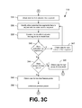
- the structure dimensioning system 119 obtains the data for the next line segment 146 and repeats boxes 326 - 330 , as shown. Once all of the line segments 146 of the group of edge pixels 139 ( FIG. 1 ) have been extended, the structure dimensioning system 119 moves to box 334 ( FIG. 3C ).
- the structure dimensioning system 119 then obtains the data for the first extended line segment 146 ( FIG. 1 ), as shown in box 334 .
- other line segments 146 that are aligned with the extended line segment 146 are identified, as shown in box 336 , and combined to create lines 149 ( FIG. 1 ), as depicted in box 338 .
- the structure dimensioning system 119 determines whether there are additional line segments to process, as shown in box 340 . If there are additional line segments 146 to process, the data for the next extended line segment 146 is obtained, as shown in box 342 , and boxes 336 - 340 are repeated at shown.
- the structure dimensioning system 119 then identifies potential planes 153 ( FIG. 1 ). As explained above, a RANSAC approach, for example, may be applied to identify the potential planes 153 .
- the structure dimensioning system 119 then obtains the data for the first line 149 (determined in box 338 of FIG. 3C ), as shown in box 352 .
- the structure dimensioning system 119 then identifies potential line 149 matches for the corresponding image frame 133 b .
- the potential line matches may be based at least in part on the potential planes 153 ( FIG. 1 ) (determined in box 336 c of FIG. 3C ) or other information.
- the best line 149 matches are identified.
- the best line 149 match may be based at least in part on edge pixels 139 ( FIG. 1 ) and their corresponding angles of gradient 156 ( FIG. 1 ), a dense point matching process, an intensity histogram, and/or possibly other factors.
- box 358 it is then determined whether there are more lines 149 to match. If so, the data for the next line 149 is obtained, as shown in box 360 , and boxes 354 - 358 are repeated as shown.
- the structure dimensioning system 119 moves to box 362 and determines whether there are more image frames 133 a to process. If so, the data for the next image frame 133 a is obtained, as shown in box 364 , and boxes 308 - 362 ( FIGS. 3A-3D ) are repeated as shown. Once all of the image frames 133 a have been processed, the structure dimensioning system 119 moves to box 366 ( FIG. 3E ).
- the data for the first and second image frames 133 a ( FIG. 1 ) are obtained, as shown in box 366 .
- the imaging set motion 157 ( FIG. 1 ) from image frame 133 a to its successive image frame 133 a is calculated.
- the structure dimensioning system 119 uses the calculated imaging set motion 157 to register three-dimensional data of the matched lines 149 with a global coordinate system, as shown in box 370 .
- the structure dimensioning system 119 then moves to box 372 and determines whether there are more image frames 133 a to process. If so, the data for the next successive frames 133 a is obtained, as shown in box 374 . As a non-limiting example, if the first image frame 133 a and second image frame 133 a were processed, the data for the second image frame 133 a and third image frame 133 a may be obtained.
- the endpoints of the matched lines 149 are adjusted, as shown in box 376 .
- the matched lines 149 may be adjusted, for example, based at least in part on epipolar geometry, homography matrices, geometric considerations, and/or possibly other information.
- the structure dimensioning system 119 generates a 3D line set 159 ( FIG. 1 ) from the lines 149 .
- a 3D line set 159 FIG. 1
- linear or non-linear triangulation methods and possibly other methods may be used to generated the 3D line set 159 from the lines 149 .
- the structure dimensioning system 119 then moves to box 380 and determines the boundaries defined by the 3D line set 159 .
- polygons are then fit to the boundaries.
- a 3D wireframe 163 ( FIG. 1 ) of the structure 126 and/or scene 129 may be generated, and as-built dimensions 123 ( FIG. 1 ) of the structure 126 ( FIG. 1 ) may be determined from the 3D wireframe 163 , as shown in box 386 .
- a materials estimate for the structure 126 or a file for the fabrication device 176 may be generated.
- the dimensions 123 and possibly other data may be transmitted to the client 196 ( FIG. 1 ), as shown in box 388 . Thereafter the process ends.
- the server computing device 103 includes at least one processor circuit, for example, having a processor 403 and a memory 406 , both of which are coupled to a local interface 409 .
- the server computing device 103 may comprise, for example, at least one server computer or like device.
- the local interface 409 may comprise, for example, a data bus with an accompanying address/control bus or other bus structure, as can be appreciated.
- Stored in the memory 406 are both data and several components that are executable by the processor 403 .
- stored in the memory 406 and executable by the processor 403 is the structure dimensioning system 119 , and potentially other applications.
- Also stored in the memory 406 may be a data store 113 and other data.
- a server operating system 413 may be stored in the memory 406 and executable by the processor 403 .
- the client computing device 106 includes at least one processor circuit, for example, having a processor 503 and a memory 506 , both of which are coupled to a local interface 509 .
- the client computing device 106 may comprise, for example, a personal computer or like device.
- the local interface 509 may comprise, for example, a data bus with an accompanying address/control bus or other bus structure, as can be appreciated.
- Stored in the memory 506 are both data and several components that are executable by the processor 503 .
- stored in the memory 506 and executable by the processor 503 is the client-side application 166 , and potentially other applications.
- a client operating system 516 may be stored in the memory 506 and executable by the processor 503 .
- any one of a number of programming languages may be employed such as, for example, C, C++, C#, Objective C, Java, Javascript, Perl, PHP, Visual Basic, Python, Ruby, Delphi, Flash, or other programming languages.
- a number of software components are stored in the memories 406 and 506 and are executable by the processors 403 and 503 , respectively.
- executable means a program file that is in a form that can ultimately be run by the processors 403 and 503 .
- Examples of executable programs may be, for example, a compiled program that can be translated into machine code in a format that can be loaded into a random access portion of the memories 406 and 506 and run by the processors 403 and 503 , respectively, source code that may be expressed in proper format such as object code that is capable of being loaded into a random access portion of the memories 406 and 506 and executed by the processors 403 and 503 , respectively, or source code that may be interpreted by another executable program to generate instructions in a random access portion of the memories 406 and 506 to be executed by the processors 403 and 503 , respectively, etc.
- An executable program may be stored in any portion or component of the memories 406 and 506 including, for example, random access memory (RAM), read-only memory (ROM), hard drive, solid-state drive, USB flash drive, memory card, optical disc such as compact disc (CD) or digital versatile disc (DVD), floppy disk, magnetic tape, or other memory components.
- RAM random access memory
- ROM read-only memory
- hard drive solid-state drive
- USB flash drive USB flash drive
- memory card such as compact disc (CD) or digital versatile disc (DVD), floppy disk, magnetic tape, or other memory components.
- CD compact disc
- DVD digital versatile disc
- the memories 406 and 506 are defined herein as including both volatile and nonvolatile memory and data storage components. Volatile components are those that do not retain data values upon loss of power. Nonvolatile components are those that retain data upon a loss of power.
- the memories 406 and 506 may comprise, for example, random access memory (RAM), read-only memory (ROM), hard disk drives, solid-state drives, USB flash drives, memory cards accessed via a memory card reader, floppy disks accessed via an associated floppy disk drive, optical discs accessed via an optical disc drive, magnetic tapes accessed via an appropriate tape drive, and/or other memory components, or a combination of any two or more of these memory components.
- the RAM may comprise, for example, static random access memory (SRAM), dynamic random access memory (DRAM), or magnetic random access memory (MRAM) and other such devices.
- the ROM may comprise, for example, a programmable read-only memory (PROM), an erasable programmable read-only memory (EPROM), an electrically erasable programmable read-only memory (EEPROM), or other like memory device.
- each processor 403 and 503 may represent multiple processors 403 and 503 , respectively, and the memories 406 and 506 may represent multiple memories 406 and 506 , respectively, that operate in parallel processing circuits, respectively.
- the local interfaces 409 and 509 may be an appropriate network 109 ( FIG. 1 ) that facilitates communication between any two of the respective multiple processors 403 and 503 , between each processor 403 and 503 and any of the memories 406 and 506 , or between any two of the memories 406 and 506 , etc.
- Each local interface 409 and 509 may comprise additional systems designed to coordinate this communication, including, for example, performing load balancing.
- the processors 403 and 503 may be of electrical or of some other available construction.
- the structure dimensioning system 119 , client-side application 166 , and other various systems described herein may be embodied in software or code executed by general purpose hardware as discussed above, as an alternative the same may also be embodied in dedicated hardware or a combination of software/general purpose hardware and dedicated hardware. If embodied in dedicated hardware, each can be implemented as a circuit or state machine that employs any one of or a combination of a number of technologies. These technologies may include, but are not limited to, discrete logic circuits having logic gates for implementing various logic functions upon an application of one or more data signals, application specific integrated circuits having appropriate logic gates, or other components, etc. Such technologies are generally well known by those skilled in the art and, consequently, are not described in detail herein.
- each block may represent a module, segment, or portion of code that comprises program instructions to implement the specified logical function(s).
- the program instructions may be embodied in the form of source code that comprises human-readable statements written in a programming language or machine code that comprises numerical instructions recognizable by a suitable execution system such as a processor 403 and 503 in a computer system or other system.
- the machine code may be converted from the source code, etc.
- each block may represent a circuit or a number of interconnected circuits to implement the specified logical function(s).
- FIGS. 2-3E show a specific order of execution, it is understood that the order of execution may differ from that which is depicted. For example, the order of execution of two or more blocks may be scrambled relative to the order shown. Also, two or more blocks shown in succession in FIGS. 2-3E may be executed concurrently or with partial concurrence. Further, in some embodiments, one or more of the blocks shown in FIGS. 2-3E may be skipped or omitted. In addition, any number of counters, state variables, warning semaphores, or messages might be added to the logical flow described herein, for purposes of enhanced utility, accounting, performance measurement, or providing troubleshooting aids, etc. It is understood that all such variations are within the scope of the present disclosure.
- any logic or application described herein, including the structure dimensioning system 119 and client-side application 166 , that comprises software or code can be embodied in any non-transitory computer-readable medium for use by or in connection with an instruction execution system such as, for example, a processor 403 and 503 in a computer system or other system.
- the logic may comprise, for example, statements including instructions and declarations that can be fetched from the computer-readable medium and executed by the instruction execution system.
- a “computer-readable medium” can be any medium that can contain, store, or maintain the logic or application described herein for use by or in connection with the instruction execution system.
- the computer-readable medium can comprise any one of many physical media such as, for example, magnetic, optical, or semiconductor media. More specific examples of a suitable computer-readable medium would include, but are not limited to, magnetic tapes, magnetic floppy diskettes, magnetic hard drives, memory cards, solid-state drives, USB flash drives, or optical discs. Also, the computer-readable medium may be a random access memory (RAM) including, for example, static random access memory (SRAM) and dynamic random access memory (DRAM), or magnetic random access memory (MRAM).
- RAM random access memory
- SRAM static random access memory
- DRAM dynamic random access memory
- MRAM magnetic random access memory
- the computer-readable medium may be a read-only memory (ROM), a programmable read-only memory (PROM), an erasable programmable read-only memory (EPROM), an electrically erasable programmable read-only memory (EEPROM), or other type of memory device.
- ROM read-only memory
- PROM programmable read-only memory
- EPROM erasable programmable read-only memory
- EEPROM electrically erasable programmable read-only memory
Landscapes
- Engineering & Computer Science (AREA)
- Physics & Mathematics (AREA)
- Theoretical Computer Science (AREA)
- General Physics & Mathematics (AREA)
- Computer Vision & Pattern Recognition (AREA)
- Multimedia (AREA)
- Geometry (AREA)
- Computing Systems (AREA)
- Computer Graphics (AREA)
- Image Analysis (AREA)
- Length Measuring Devices By Optical Means (AREA)
- Image Processing (AREA)
Priority Applications (1)
| Application Number | Priority Date | Filing Date | Title |
|---|---|---|---|
| US13/644,523 US8897539B2 (en) | 2011-10-04 | 2012-10-04 | Using images to create measurements of structures through the videogrammetric process |
Applications Claiming Priority (2)
| Application Number | Priority Date | Filing Date | Title |
|---|---|---|---|
| US201161543167P | 2011-10-04 | 2011-10-04 | |
| US13/644,523 US8897539B2 (en) | 2011-10-04 | 2012-10-04 | Using images to create measurements of structures through the videogrammetric process |
Publications (2)
| Publication Number | Publication Date |
|---|---|
| US20130083990A1 US20130083990A1 (en) | 2013-04-04 |
| US8897539B2 true US8897539B2 (en) | 2014-11-25 |
Family
ID=47992643
Family Applications (1)
| Application Number | Title | Priority Date | Filing Date |
|---|---|---|---|
| US13/644,523 Active 2033-01-27 US8897539B2 (en) | 2011-10-04 | 2012-10-04 | Using images to create measurements of structures through the videogrammetric process |
Country Status (5)
| Country | Link |
|---|---|
| US (1) | US8897539B2 (de) |
| EP (1) | EP2764325A4 (de) |
| AU (1) | AU2012318657A1 (de) |
| CA (1) | CA2850937A1 (de) |
| WO (1) | WO2013052600A1 (de) |
Cited By (11)
| Publication number | Priority date | Publication date | Assignee | Title |
|---|---|---|---|---|
| US20150139535A1 (en) * | 2013-11-18 | 2015-05-21 | Nant Holdings Ip, Llc | Silhouette-based object and texture alignment, systems and methods |
| US9460517B2 (en) | 2014-10-22 | 2016-10-04 | Pointivo, Inc | Photogrammetric methods and devices related thereto |
| US9904867B2 (en) | 2016-01-29 | 2018-02-27 | Pointivo, Inc. | Systems and methods for extracting information about objects from scene information |
| US9990565B2 (en) | 2013-04-11 | 2018-06-05 | Digimarc Corporation | Methods for object recognition and related arrangements |
| US10217207B2 (en) | 2016-01-20 | 2019-02-26 | Ez3D, Llc | System and method for structural inspection and construction estimation using an unmanned aerial vehicle |
| US10825567B1 (en) | 2015-08-21 | 2020-11-03 | Food2Life, LLC | Apparatus and method for informed personal well-being decision making |
| US10896353B2 (en) | 2013-08-02 | 2021-01-19 | Xactware Solutions, Inc. | System and method for detecting features in aerial images using disparity mapping and segmentation techniques |
| US11043026B1 (en) | 2017-01-28 | 2021-06-22 | Pointivo, Inc. | Systems and methods for processing 2D/3D data for structures of interest in a scene and wireframes generated therefrom |
| US11094113B2 (en) | 2019-12-04 | 2021-08-17 | Geomni, Inc. | Systems and methods for modeling structures using point clouds derived from stereoscopic image pairs |
| US11210433B2 (en) | 2012-02-15 | 2021-12-28 | Xactware Solutions, Inc. | System and method for construction estimation using aerial images |
| US11266125B1 (en) | 2018-08-06 | 2022-03-08 | American Institute of Nutrition and Management Inc. | System and method for animal growth regulation for improved profitability and mitigated risk |
Families Citing this family (5)
| Publication number | Priority date | Publication date | Assignee | Title |
|---|---|---|---|---|
| US10909482B2 (en) * | 2013-03-15 | 2021-02-02 | Pictometry International Corp. | Building materials estimation |
| US9787882B1 (en) * | 2014-05-30 | 2017-10-10 | Kenneth Arie VanBree | System for generating and displaying discontinuous time-lapse image sequences |
| CN107609632A (zh) * | 2017-09-15 | 2018-01-19 | 国家电网公司 | 配电网重构优化运行分析方法及装置 |
| CA3105309A1 (en) * | 2018-06-29 | 2020-01-02 | Geomni, Inc. | Computer vision systems and methods for modeling three dimensional structures using two-dimensional segments detected in digital aerial images |
| CN110375659B (zh) * | 2018-09-11 | 2021-07-27 | 百度在线网络技术(北京)有限公司 | 检测障碍物高度的方法、装置、设备及存储介质 |
Citations (5)
| Publication number | Priority date | Publication date | Assignee | Title |
|---|---|---|---|---|
| US6154578A (en) | 1997-03-31 | 2000-11-28 | Samsung Electronics Co., Ltd. | Method for motion compensation of a moving image using two dimensional triangle patch wireframe model |
| US7136077B2 (en) * | 2004-06-09 | 2006-11-14 | International Business Machines Corporation | System, method, and article of manufacture for shading computer graphics |
| US20090141020A1 (en) | 2007-12-03 | 2009-06-04 | Freund Joseph G | Systems and methods for rapid three-dimensional modeling with real facade texture |
| US20100110074A1 (en) | 2008-10-31 | 2010-05-06 | Eagle View Technologies, Inc. | Pitch determination systems and methods for aerial roof estimation |
| US20110174128A1 (en) | 2010-01-18 | 2011-07-21 | Metalforming, Inc. | Programmable roll former and angle cutter |
Family Cites Families (4)
| Publication number | Priority date | Publication date | Assignee | Title |
|---|---|---|---|---|
| KR100356016B1 (ko) * | 1999-12-21 | 2002-10-18 | 한국전자통신연구원 | 영상인식에 의한 소포우편물 부피계측시스템 및부피계측방법 |
| KR100422370B1 (ko) * | 2000-12-27 | 2004-03-18 | 한국전자통신연구원 | 3차원 물체 부피계측시스템 및 방법 |
| US8350850B2 (en) * | 2008-03-31 | 2013-01-08 | Microsoft Corporation | Using photo collections for three dimensional modeling |
| WO2010044939A1 (en) * | 2008-10-17 | 2010-04-22 | Honda Motor Co., Ltd. | Structure and motion with stereo using lines |
-
2012
- 2012-10-04 US US13/644,523 patent/US8897539B2/en active Active
- 2012-10-04 AU AU2012318657A patent/AU2012318657A1/en not_active Abandoned
- 2012-10-04 EP EP12838383.3A patent/EP2764325A4/de not_active Withdrawn
- 2012-10-04 WO PCT/US2012/058650 patent/WO2013052600A1/en active Application Filing
- 2012-10-04 CA CA2850937A patent/CA2850937A1/en not_active Abandoned
Patent Citations (5)
| Publication number | Priority date | Publication date | Assignee | Title |
|---|---|---|---|---|
| US6154578A (en) | 1997-03-31 | 2000-11-28 | Samsung Electronics Co., Ltd. | Method for motion compensation of a moving image using two dimensional triangle patch wireframe model |
| US7136077B2 (en) * | 2004-06-09 | 2006-11-14 | International Business Machines Corporation | System, method, and article of manufacture for shading computer graphics |
| US20090141020A1 (en) | 2007-12-03 | 2009-06-04 | Freund Joseph G | Systems and methods for rapid three-dimensional modeling with real facade texture |
| US20100110074A1 (en) | 2008-10-31 | 2010-05-06 | Eagle View Technologies, Inc. | Pitch determination systems and methods for aerial roof estimation |
| US20110174128A1 (en) | 2010-01-18 | 2011-07-21 | Metalforming, Inc. | Programmable roll former and angle cutter |
Non-Patent Citations (21)
| Title |
|---|
| Bartoli, A., & Sturm, P. (2005). Structure-from-motion using lines: Representation, triangulation, and bundle adjustment. Computer Vision and Image Understanding, 100(3), 416-441. |
| Bay, H., Tuytelaars, T., & Van Gool, L. (2006). SURF: Speeded up robust features. Computer Vision-ECCV 2006, 404-417. |
| Chandraker, M., Lim, J., & Kriegman, D. (Sep. 2009). Moving in stereo: Efficient structure and motion using lines. In Computer Vision, 2009 IEEE 12th International Conference on (pp. 1741-1748). IEEE. |
| Coaker, L. H. (2009). Reflector-less total station measurements and their accuracy, precision and reliability. Dissertation, University of South Queensland. |
| Cory, J. (2009), "Roofing contractors make use of a new estimating tool they say is safer and more accurate than hand-measuring: satellites", Replacement Contractor, May, www.replacementcontractoronline.com/industry-news.asp?section ID=316>. |
| Gallup, D. (2011), "Efficient 3D reconstruction of a large-scale urban environments from street-level video", Dissertation, University of North Carolina. |
| Goesele, et al. (2007), "Mutli-view stereo for community photo collections", International Conference on Computer Vision, Seattle. |
| Goesele, M., Snavely, N., Curless, B., Hoppe, H., & Seitz, S. M. (Oct. 2007). Multi-view stereo for community photo collections. In Computer Vision, 2007. ICCV 2007. IEEE 11th International Conference on (pp. 1-8). IEEE. |
| Hartley, R. I. (1997). Lines and points in three views and the trifocal tensor. International Journal of Computer Vision, 22(2), 125-140. |
| Khaleghi, B., Baklouti, M., & Karray, F. O. (Dec. 2009). SILT: scale-invariant line transform. In Computational Intelligence in Robotics and Automation (CIRA), 2009 IEEE International Symposium on (pp. 78-83). IEEE. |
| Lin, et al., "Non-Contact Monitoring System for Investigating As-Built Membrane Roof Structures" APRS, vol. XXXVI, Part 5, Dresden Sep. 25-27, 2006. |
| Lowe, D. G. (2004). Distinctive image features from scale-invariant keypoints. International Journal of Computer Vision, 60(2), 91-110. |
| PCT International Search Report received Jan. 23, 2013. |
| Pollefeys, M. et al. (2008). Detailed real-time urban 3d reconstruction from video. International Journal of Computer Vision, 78(2), 143-167. |
| Pradeep, V., & Lim, J. (Jun. 2010). Egomotion using assorted features. In Computer Vision and Pattern Recognition (CVPR), 2010 IEEE Conference on (pp. 1514-1521). IEEE. |
| Schindler, G., Krishnamurthy, P., & Dellaert, F. (Jun. 2006). Line-based structure from motion for urban environments. In 3D Data Processing, Visualization, and Transmission, Third International Symposium on (pp. 846-853). IEEE. |
| Sourimant, et al., "GPS, GIS and Video Registration for Building Reconstruction," 2007, retrieved on Nov. 20, 2012. |
| Tang, P., Akinci, B., & Huber, D. (2009). Quantification of edge loss of laser scanned data at spatial discontinuities. Automation in Construction, 18(8), 1070-1083. |
| Taylor, C. J., & Kriegman, D. J. (1995). Structure and motion from line segments in multiple images. Pattern Analysis and Machine Intelligence, IEEE Transactions on, 17(11), 1021-1032. |
| Wang, Z., Wu, F., & Hu, Z. (2009). MSLD: A robust descriptor for line matching. Pattern Recognition, 42(5), 941-953. |
| Werner, T., & Zisserman, A. (2002). New techniques for automated architectural reconstruction from photographs. Computer Vision-ECCV 2002, 808-809. |
Cited By (22)
| Publication number | Priority date | Publication date | Assignee | Title |
|---|---|---|---|---|
| US11727163B2 (en) | 2012-02-15 | 2023-08-15 | Xactware Solutions, Inc. | System and method for construction estimation using aerial images |
| US11210433B2 (en) | 2012-02-15 | 2021-12-28 | Xactware Solutions, Inc. | System and method for construction estimation using aerial images |
| US9990565B2 (en) | 2013-04-11 | 2018-06-05 | Digimarc Corporation | Methods for object recognition and related arrangements |
| US10896353B2 (en) | 2013-08-02 | 2021-01-19 | Xactware Solutions, Inc. | System and method for detecting features in aerial images using disparity mapping and segmentation techniques |
| US11144795B2 (en) | 2013-08-02 | 2021-10-12 | Xactware Solutions, Inc. | System and method for detecting features in aerial images using disparity mapping and segmentation techniques |
| US9489765B2 (en) * | 2013-11-18 | 2016-11-08 | Nant Holdings Ip, Llc | Silhouette-based object and texture alignment, systems and methods |
| US9728012B2 (en) | 2013-11-18 | 2017-08-08 | Nant Holdings Ip, Llc | Silhouette-based object and texture alignment, systems and methods |
| US9940756B2 (en) | 2013-11-18 | 2018-04-10 | Nant Holdings Ip, Llc | Silhouette-based object and texture alignment, systems and methods |
| US20150139535A1 (en) * | 2013-11-18 | 2015-05-21 | Nant Holdings Ip, Llc | Silhouette-based object and texture alignment, systems and methods |
| US9460517B2 (en) | 2014-10-22 | 2016-10-04 | Pointivo, Inc | Photogrammetric methods and devices related thereto |
| US9886774B2 (en) | 2014-10-22 | 2018-02-06 | Pointivo, Inc. | Photogrammetric methods and devices related thereto |
| US10825567B1 (en) | 2015-08-21 | 2020-11-03 | Food2Life, LLC | Apparatus and method for informed personal well-being decision making |
| US10853931B2 (en) | 2016-01-20 | 2020-12-01 | Ez3D Technologies, Inc. | System and method for structural inspection and construction estimation using an unmanned aerial vehicle |
| US10217207B2 (en) | 2016-01-20 | 2019-02-26 | Ez3D, Llc | System and method for structural inspection and construction estimation using an unmanned aerial vehicle |
| US10592765B2 (en) | 2016-01-29 | 2020-03-17 | Pointivo, Inc. | Systems and methods for generating information about a building from images of the building |
| US11244189B2 (en) | 2016-01-29 | 2022-02-08 | Pointivo, Inc. | Systems and methods for extracting information about objects from scene information |
| US9904867B2 (en) | 2016-01-29 | 2018-02-27 | Pointivo, Inc. | Systems and methods for extracting information about objects from scene information |
| US11043026B1 (en) | 2017-01-28 | 2021-06-22 | Pointivo, Inc. | Systems and methods for processing 2D/3D data for structures of interest in a scene and wireframes generated therefrom |
| US11266125B1 (en) | 2018-08-06 | 2022-03-08 | American Institute of Nutrition and Management Inc. | System and method for animal growth regulation for improved profitability and mitigated risk |
| US11751542B1 (en) | 2018-08-06 | 2023-09-12 | American Institute of Nutrition and Management Inc. | Method and system for animal growth regulation for improved profitability and mitigated risk |
| US11094113B2 (en) | 2019-12-04 | 2021-08-17 | Geomni, Inc. | Systems and methods for modeling structures using point clouds derived from stereoscopic image pairs |
| US11915368B2 (en) | 2019-12-04 | 2024-02-27 | Insurance Services Office, Inc. | Systems and methods for modeling structures using point clouds derived from stereoscopic image pairs |
Also Published As
| Publication number | Publication date |
|---|---|
| AU2012318657A1 (en) | 2014-05-22 |
| WO2013052600A1 (en) | 2013-04-11 |
| EP2764325A4 (de) | 2016-01-06 |
| CA2850937A1 (en) | 2013-04-11 |
| EP2764325A1 (de) | 2014-08-13 |
| AU2012318657A8 (en) | 2014-06-12 |
| US20130083990A1 (en) | 2013-04-04 |
Similar Documents
| Publication | Publication Date | Title |
|---|---|---|
| US8897539B2 (en) | Using images to create measurements of structures through the videogrammetric process | |
| Zhang et al. | Content-aware unsupervised deep homography estimation | |
| US10360247B2 (en) | System and method for telecom inventory management | |
| US10311595B2 (en) | Image processing device and its control method, imaging apparatus, and storage medium | |
| JP5580164B2 (ja) | 光学情報処理装置、光学情報処理方法、光学情報処理システム、光学情報処理プログラム | |
| CN105765628B (zh) | 深度图生成的方法及系统 | |
| EP3093822A1 (de) | Darstellung eines in einer bildsequenz abgebildeten zielobjekts | |
| CN111145270A (zh) | 基于光学动捕的大空间环境下多相机标定方法及相关设备 | |
| CN110619807B (zh) | 生成全局热力图的方法和装置 | |
| US20220180560A1 (en) | Camera calibration apparatus, camera calibration method, and nontransitory computer readable medium storing program | |
| KR20160117143A (ko) | 실내 2d 평면도의 생성 방법, 장치 및 시스템 | |
| CN110111241B (zh) | 用于生成动态图像的方法和装置 | |
| US10600202B2 (en) | Information processing device and method, and program | |
| Kim et al. | Fast and robust geometric correction for mosaicking UAV images with narrow overlaps | |
| Guidi et al. | Optimal lateral displacement in automatic close-range photogrammetry | |
| Hofmann et al. | Efficiently annotating object images with absolute size information using mobile devices | |
| CN105783881A (zh) | 空中三角测量的方法和装置 | |
| US9721371B2 (en) | Systems and methods for stitching metallographic and stereoscopic images | |
| US9842402B1 (en) | Detecting foreground regions in panoramic video frames | |
| US9824455B1 (en) | Detecting foreground regions in video frames | |
| Altuntas | Pair-wise automatic registration of three-dimensional laser scanning data from historical building by created two-dimensional images | |
| CN112215036B (zh) | 跨镜追踪方法、装置、设备及存储介质 | |
| Idrissa et al. | Generic epipolar resampling method for perspective frame camera and linear push-broom sensor | |
| CN108650465B (zh) | 摄像机画面增强现实标签的计算方法、装置及电子设备 | |
| Ahn et al. | Research of panoramic image generation using IoT device with camera for cloud computing environment |
Legal Events
| Date | Code | Title | Description |
|---|---|---|---|
| AS | Assignment |
Owner name: METALFORMING, INC., GEORGIA Free format text: ASSIGNMENT OF ASSIGNORS INTEREST;ASSIGNORS:STONE, GEOFFREY;FATHI, HABIB;BRILAKIS, IOANNIS;SIGNING DATES FROM 20111005 TO 20111130;REEL/FRAME:031069/0043 Owner name: METALFORMING, INC., GEORGIA Free format text: ASSIGNMENT OF ASSIGNORS INTEREST;ASSIGNORS:STONE, GEOFFREY;WILKINS, WILLIAM GAITHER;REEL/FRAME:031069/0106 Effective date: 20121018 |
|
| STCF | Information on status: patent grant |
Free format text: PATENTED CASE |
|
| MAFP | Maintenance fee payment |
Free format text: PAYMENT OF MAINTENANCE FEE, 4TH YR, SMALL ENTITY (ORIGINAL EVENT CODE: M2551) Year of fee payment: 4 |
|
| AS | Assignment |
Owner name: POINTIVO, INC., GEORGIA Free format text: ASSIGNMENT OF ASSIGNORS INTEREST;ASSIGNOR:METALFORMING, INC.;REEL/FRAME:047983/0550 Effective date: 20170601 |
|
| AS | Assignment |
Owner name: SILICON VALLEY BANK, CALIFORNIA Free format text: SECURITY INTEREST;ASSIGNOR:POINTIVO, INC.;REEL/FRAME:050354/0645 Effective date: 20190910 |
|
| MAFP | Maintenance fee payment |
Free format text: PAYMENT OF MAINTENANCE FEE, 8TH YR, SMALL ENTITY (ORIGINAL EVENT CODE: M2552); ENTITY STATUS OF PATENT OWNER: SMALL ENTITY Year of fee payment: 8 |
|
| AS | Assignment |
Owner name: SILICON VALLEY BANK, CALIFORNIA Free format text: RELEASE BY SECURED PARTY;ASSIGNOR:POINTIVO, INC.;REEL/FRAME:061374/0665 Effective date: 20221007 |