US8896401B1 - Calibration and tuning using compact multi frequency-range impedance tuners - Google Patents
Calibration and tuning using compact multi frequency-range impedance tuners Download PDFInfo
- Publication number
- US8896401B1 US8896401B1 US13/845,607 US201313845607A US8896401B1 US 8896401 B1 US8896401 B1 US 8896401B1 US 201313845607 A US201313845607 A US 201313845607A US 8896401 B1 US8896401 B1 US 8896401B1
- Authority
- US
- United States
- Prior art keywords
- tuner
- module
- frequency
- parameters
- tuners
- Prior art date
- Legal status (The legal status is an assumption and is not a legal conclusion. Google has not performed a legal analysis and makes no representation as to the accuracy of the status listed.)
- Expired - Fee Related, expires
Links
Images


Classifications
-
- H—ELECTRICITY
- H01—ELECTRIC ELEMENTS
- H01P—WAVEGUIDES; RESONATORS, LINES, OR OTHER DEVICES OF THE WAVEGUIDE TYPE
- H01P5/00—Coupling devices of the waveguide type
- H01P5/04—Coupling devices of the waveguide type with variable factor of coupling
-
- H—ELECTRICITY
- H03—ELECTRONIC CIRCUITRY
- H03H—IMPEDANCE NETWORKS, e.g. RESONANT CIRCUITS; RESONATORS
- H03H7/00—Multiple-port networks comprising only passive electrical elements as network components
- H03H7/38—Impedance-matching networks
- H03H7/40—Automatic matching of load impedance to source impedance
-
- H—ELECTRICITY
- H03—ELECTRONIC CIRCUITRY
- H03H—IMPEDANCE NETWORKS, e.g. RESONANT CIRCUITS; RESONATORS
- H03H7/00—Multiple-port networks comprising only passive electrical elements as network components
- H03H7/38—Impedance-matching networks
Definitions
- This invention relates to load pull testing of microwave power transistors using automatic microwave tuners in order to synthesize reflection factors (or impedances) at the input and output of said transistors.
- Load pull or source pull are measurement techniques employing microwave tuners and other microwave test equipment, such as signal sources, power meters and directional couplers.
- the microwave tuners in particular are used in order to manipulate the microwave impedance conditions under which the Device under Test (DUT, or transistor) is tested ( FIG. 1 a ).
- tuner unit being able to operate over such wide frequency ranges would then be required, but has not been introduced, yet.
- Electro-mechanical impedance tuners are, by their nature, limited in frequency bandwidth. Therefore various techniques must be used to respond to this requirement.
- a popular family of electro-mechanical tuners use adjustable RF probes (slugs) inserted into the transmission media of the tuners and capacitively coupled with the central conductor ( FIG. 1 b ) of the transmission media which is, in general, a slotted coaxial or parallel plate airline (slabline); this insertion of the slug reflects part of the power coming out of the DUT and creates a reflection factor ( ⁇ ) or impedance (Z) that is presented to the DUT.
- the ‘slide-screw’ principle is a tuning mechanism where the capacitive coupling between the RF probe and the central conductor of the slotted airline (slabline) creates a wideband reflection factor ⁇ of which the amplitude can be adjusted by modifying the distance “S” between the probe and the central conductor and therefore changing the value of the capacitance between the central conductor and the RF probe.
- the RF probe In order to change the phase of the reflection factor ⁇ the RF probe, already inserted in the slabline, must be moved horizontally along the axis of the slabline, ( FIG. 1 b ).
- a metallic probe in a low loss slabline creates maximum reflection, but has a limited frequency range.
- the probe has a capacitive effect but does not behave purely as a capacitor, because of electro-magnetic field deformation.
- an extended structure employs three RF probes, in parallel ( FIGS. 4 a , 4 b ).
- the ultimo limit in bandwidth is mechanical stability of the central conductor of the slotted airline (slabline).
- the mechanical stability of any unsupported metallic (steel) rod depends on its ratio of total length to diameter. If this ratio exceeds 100:1 then the structure is critical.
- Slide screw tuners require a total horizontal travel length of 1 ⁇ 2 wavelengths. At 1 GHz this corresponds to 15 cm, at 100 MHz to 150 cm and at 10 MHz to 1,500 cm (15 meters). It is obvious that at frequencies below a few hundred megahertz the size of a slide screw tuner is prohibitive. For this frequency range a different technology is used [ 6 ], ( FIGS. 6 a , 6 b , 22 ), which employs low frequency adjustable capacitors and selected lengths of flexible or semi-rigid coaxial cable between them, allowing this way, controllable high reflection factors from under 10 MHz and up to 1 GHz.
- the capacitors used are either “trimmer type capacitors” [ 3 ] for the higher end of frequencies, or “parallel blade capacitors” [ 7 ] for the lower end.
- the high end starts around 200 MHz and stops at around 1 GHz and the low end starts at around 10 MHz and stops around 200 MHz.
- At least three capacitors are required in order to tune all over the Smith chart, but, in order to reach continuous coverage of the whole frequency range four or five capacitors and associated transmission lines may be used ( FIGS. 6 a , 6 b ).
- a capacitor/transmission line based tuner is based on the principle, that at least three reflection vectors of adjustable size but fixed angle between them can synthesize a resulting reflection factor vector, which covers a large portion of the Smith chart ( FIG. 8 ). Because the angle between vectors is fixed the bandwidth of said tuner is limited and the maximum reflection created is not fully flat over the whole frequency range. If three capacitor/line sections are insufficient, because of the ripple in S11max, which is caused by the fact that the phase of the cable sections is not 60 degrees for all frequencies, a fourth or even fifth section can be added to compensate and cover the missing zones of frequency and reflection factor.
- the tuning mechanism is sketched in FIGS. 7 , 8 .
- FIG. 1 depicts prior art: a) typical load pull setup using impedance tuners; b) Cross section of electro-mechanical slide screw tuner; c) prior art: Tuning mechanism of slide screw tuner.
- FIG. 2 depicts prior art: a) triple probe tuner for ultra stable and harmonic tuning; b) wideband tuner using two RF probes, one small probe for high frequencies and one large probe for low frequencies.
- FIG. 3 depicts prior art: a) frequency response of triple (identical probes) and b) double (different probes) tuners.
- FIG. 4 depicts prior art: a) Wideband tuner with triple carriage and three probes of different size covering adjacent frequency bands b).
- FIG. 5 depicts a Cascade of two tuners covering different frequency ranges, allows extending the overall bandwidth; the high frequency tuner is also shorter (L1 ⁇ L2) because of the shorter wavelength.
- FIG. 6 depicts three (a) (prior art) and four (b) “variable capacitor-transmission line” low frequency tuners. Higher number of sections provides better bandwidth and tuning flatness. Transmission lines are flexible or semi-rigid coaxial cables wound in coil form in order to reduce overall tuner size.
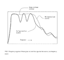
- FIG. 7 depicts the frequency response of three (prior art) and five capacitor-line section, low frequency tuners
- FIG. 8 depicts the impedance coverage of three capacitor-line section tuner (sections a, b, c) and improvement of coverage due to a fourth capacitor-line section (d).
- FIG. 9 depicts prior art: Parallel blade and trimmer capacitors and their electrical RF equivalent circuit indicating the maximum operation frequency: Freq-Max. Beyond this frequency the capacitors act like inductances. Trimmer capacitors operate up to about 1000 MHz, whereas parallel blade capacitors can go up to 150 MHz, always depending on Cmax.
- FIG. 10 depicts prior art: structure of low frequency tuner using three variable parallel blade capacitors and three lengths of coaxial cable (the last section L4 of cable is not useable for tuning purposes); parallel blade capacitors operate at lower frequencies.
- the lengths of coaxial cable can be wound in coil-form in order to reduce the overall length.
- FIG. 11 depicts prior art: automated low frequency tuner, using stepper motors.
- FIG. 12 depicts the residual reflection of capacitor based low frequency tuner as a function of frequency, over a wide frequency range, reaching beyond the tuner's operating bandwidth (cross-over frequency).
- FIG. 13 depicts the typical maximum and residual reflection of low frequency and high frequency tuners over the whole frequency range of the cascade of two tuners.
- FIG. 14 depicts the tuning capability of a cascade of a high frequency with a low frequency (with high residual reflection) tuner.
- FIG. 15 depicts a) a cascade of two impedance tuners [a] and [b] with possibility of bypassing the low frequency unit using a capacitor.
- ⁇ 1 and ⁇ 2 are the reflection factors at the test port of each module; b) the equivalent circuit used to demonstrate the effect of the bypass capacitor C.
- FIG. 16 depicts a) a cascade of two impedance tuners [a] and [b] with possibility of bypassing the low frequency unit using a switchable capacitor C. b) The cascade of two impedance tuners [a] and [b] with possibility of bypassing the low frequency unit using a permanent capacitor C; c) the wideband frequency response of residual reflection of low frequency tuner, with and without bypass capacitor.
- FIG. 17 depicts the structure of a wideband tuner using a cascade of a slide screw tuner and a low frequency tuner with three variable trimmer capacitors and three lengths of coaxial cable; trimmer capacitors operate at high end of megahertz frequencies.
- FIG. 18 depicts the structure of a wideband tuner using a cascade of a wideband slide screw tuner with three probes and a low frequency tuner with three variable parallel blade capacitors and three lengths of coaxial cable; parallel blade capacitors operate at the low end of megahertz frequencies; the low frequency tuner module can be bypassed by an appropriate capacitor.
- FIG. 19 depicts a wideband tuner using a cascade of a slide screw tuner with two probes and a low frequency tuner with four variable parallel blade capacitors and four lengths of coaxial cable.
- FIG. 20 depicts a cascade of three tuner units, providing multi-decade frequency coverage
- FIG. 21 depicts a cascade of a trimmer based tuner with a parallel-blade capacitor tuner; the parallel-blade capacitor tuner can be bypassed using an (optional) bypass capacitor in order to reduce off-band residual reflections.
- FIG. 22 depicts prior art, the structure of low frequency tuner using a variable capacitor (parallel-blade [ 7 ] or trimmer [ 3 ], depending on the frequency range) and a variable in-line phase shifter [ 8 ].
- FIG. 23 depicts the structure of a wideband tuner using a cascade of a slide screw tuner and a low frequency tuner with three variable trimmer capacitors and three lengths of coaxial cable; the low frequency tuner can be bypassed using an (optional) bypass capacitor, in order to reduce its residual reflection at high frequencies.
- FIG. 24 depicts the cascade of a wideband high frequency tuner with a low frequency tuner and capability of inserting a bypass capacitor.
- FIG. 25 depicts a compact assembly of slide screw with capacitor based wideband tuners (top view).
- FIG. 26 depicts prior art, a test setup for calibrating an impedance tuner on a vector network analyzer (VNA).
- VNA vector network analyzer
- This invention describes a microwave impedance tuner apparatus which covers instantaneously a very large frequency bandwidth of up to 10 or 16 octaves or up to 3.6 decades (10 or 50 MHz to 6, 18, 40 or 50 GHz). Such an endeavor has never been considered before. In fact it is possible, when appropriate technologies are used and are combined with associated tuning algorithms, which allow the tuners in cascade to compensate for each-other's residual reflections. In order to understand this operation we need to review the residual reflections of the low frequency tuners at high frequencies ( FIGS. 7 , 12 ).
- tuners covering different bandwidths and consists in cascading two such tuners ( FIG. 5 ); said tuners may cover adjacent but also non-adjacent frequency bands.
- the purpose of such a configuration would be to use a once assembled test setup for a wide frequency range without swapping tuners or recalibrating all the components and the tuners separately.
- Said low frequency tuners can be made using three or more variable capacitors and associated pre-selected and fixed sections of flexible or semi-rigid coaxial cable ( FIGS. 6 a , 6 b , 10 , 22 ).
- the frequency coverage is not fully flat ( FIG. 7 ); in order to create a fully flat frequency response a larger number of capacitor-line sections are required ( FIGS. 6 b , 7 ).
- the capacitor positions are registered in tuner calibration files with the associated s-parameters of the tuner itself at all frequencies of interest. Said calibration data are then used for later tuning purposes.
- the capacitors are controlled using stepper motors ( FIGS. 11 , 25 ). Said stepper motors are controlled by a system computer running appropriate control software.
- FIG. 22 An alternative structure for low frequency tuners is shown in FIG. 22 . It consists of a linear phase shifter ahead of a shunt variable capacitor. The capacitor creates a reflection factor vector at any given frequency and the phase shifter rotates this vector to cover most of the Smith chart. Manufacturing of low frequency linear phase shifters has been described in [ 8 ].
- Resonance Frequency: Freq-Max 1/(2 ⁇ sqrt( Ls*C max)) ⁇ 3 ⁇
- each capacitor may vary from a few megahertz up to a few gigahertz. What is important in the whole structure is the minimum impedance (or maximum reflection factor) that can be created at the lowest frequency of operation, using any particular capacitor.
- Parallel-blade capacitors may reach a couple of hundred megahertz maximum frequency whereas trimmer capacitors can still operate beyond one gigahertz.
- Such capacitors have resonance frequencies in the range of 100 MHz. What is important also is to realize that the necessary low impedance can be reached at higher frequencies with the capacitors set not to the position of maximum capacitance.
- the capacitance needed for 55 ⁇ at 100 MHz would be 10 times smaller, i.e. 318 pF, in which case the resonance frequency would (ideally) be approximately 3 times higher (eq. ⁇ 3 ⁇ postulates that max-freq follows a square root (sqrt) rule with Cmax).
- tuning with a cascade of inhomogeneous tuners like the present apparatus ( FIG. 15 a ), means, first of all, acquiring the required calibration data for all tuners at all frequencies and then tuning with all (two or three) tuners at the same time in the following steps: after selecting the frequency of operation, it has to be decided which tuner will perform the tuning, i.e. in which' tuners frequency range the selected frequency falls; if the selected frequency falls inside the lowest frequency's tuner range then the highest frequency tuner (the slide screw tuner) will have all its probes retracted from the transmission line, because said transmission line has a perfect low-pass behavior, i.e. it does not create noticeable reflections at low frequencies ( FIG.
- the effect of the low frequency tuner can be either partly compensated when a fixed capacitor of appropriate value is connected, either permanently or temporarily (with the help of an RF switch) between the tuner test port and the load ( FIGS. 15 a , 21 , 23 , 24 ).
- This technique can be applied for all tuner configurations, where one unit has a non-negligible residual reflection, or it cannot be driven to synthesize a small reflection at the selected (high) frequency, such as to allow the first (high frequency) tuner to tune to all desired impedances (FIGS. 14 , 16 ).
- the (optional and/or switchable) bypass capacitor C, followed by a resistor of 50 ⁇ will collect the “z” part of the signal injected into node (X) and allow the “y” part to reach the test port of the low frequency tuner. This way the load impedance, seen by the high frequency tuner at its output port will be driven towards 50 ⁇ with increasing frequency.
- the side-effect of this operation is an increased (low frequency) tuner loss, but this can be taken care of accurately using calibration data. Insertion loss of load tuners is irrelevant, what is important is their reflection factor and how this can be maximized.
- an alternative setup provides for such a bypass capacitor to be connected between the test port of the low frequency tuner and the load directly ( FIG. 16 a ), with a provision of having the idle port of said low frequency tuner disconnected, if the impedance of said tuner at said idle port is low, compared with 50 ⁇ . If said impedance at the idle port is high compared with 50 ⁇ , then the idle port may remain connected.
- This setup works best when the low frequency tuner has high internal impedance at both, the test and idle ports; this depends on the capacitor settings of said low frequency tuner, which are saved as part of the calibration data file, as described later. It also depends on the fringe elements associated with connecting low frequency capacitors to coaxial cables and internal parasitic elements of said capacitors, which will appear at high frequencies.
- the effect of the bypassing capacitor can be seen in FIGS. 15 b , 16 ; it shows a flattening and subsequent reduction of residual reflection factor above the cross-over frequency.
- low frequency tuners using shunt capacitors and coaxial lines have a bad high pass behavior, i.e. they present a high residual reflection at high frequencies. This would shift the tuning range of the high frequency tuner ( FIG. 14 ) and it may or may not allow proper tuning in all areas of the Smith chart.
- a capacitor, bridging over the low frequency tuner, between said tuner's test port and output port FIGS. 15 a , 15 b ).
- the bypassing capacitor must be selected such as not to short-circuit the tuning capacity of the low frequency tuner itself, though. This may not be obvious in the region of the cross-over frequency ( FIG. 16 c ).
- Cross-over frequency is defined as the frequency at which the low frequency tuner stops operating and the high frequency tuner takes over.
- said parallel capacitor may be changed or even removed from the network using RF plugs or switches ( FIGS. 15 a , 21 , 23 , 24 ), or more than one capacitor can be used to adapt to the various frequency ranges. All this will be decided once all tuners are calibrated and the tuning algorithm executes the task of tuning, in which case the tuning capacity of the system can be concretely assessed.
- the bypass capacitor technique is most effective when the low frequency tuner is tuned to the highest impedance at the test and idle ports ( FIG. 16 b ). This may be when the capacitors are set to their smallest values, or to some other value that creates high impedance parallel resonance. For the tuner operation this is irrelevant, because the calibration data contain a full characterization of the low frequency tuner and allow the tuning algorithm to select the best settings for this purpose.
- the point is that, only the slide-screw type tuner section requires a straight precision slotted airline as transmission media; the length of said airline is slightly larger than half a wavelength at the lowest frequency; a, mechanically acceptable length being 25 cm (corresponding to a minimum frequency of 800 MHz approximately; this includes horizontal free travel of the RF tuner probe plus some length for sidewalls, moving gear etc.), we need capacitor based tuners for frequencies up to 800 MHz, approximately. These lower frequency tuners then use three or more capacitance sections, but the coaxial cable connecting said sections is usually semi-rigid or flexible and can be would in coil form to a highly reduced overall length.
- FIGS. 17 to 21 and 23 , 24 show various possible configurations using combinations of slide screw (high frequency) tuners and capacitor based (low frequency) tuners, said low frequency tuners using either parallel blade or trimmer capacitors.
- Possible configurations of parallel blade and trimmer based capacitor tuners are shown as well, those latter configurations allowing coverage from the low megahertz frequencies up to several hundred megahertz or low gigahertz range. In fact, as long as attention is being paid to accommodate for high frequency tuning in view of the high residual reflection of the low frequency tuners, any combination of said low and high frequency tuners is viable.
- FIG. 25 shows, schematically, the compact assembly of the slide screw (high frequency) with the capacitor based (low frequency) tuners.
- Said configuration may cover 50 MHz to 18 GHz and would, otherwise require a linear length of more than 3 meters, whereas the assembly shown in FIG. 25 is only around 40 ⁇ 40 cm 2 , a typical size for a laboratory instrument; the lower the lowest frequency, of course, the higher the gains in size.
- Calibrating the tuner(s) consists in simply connecting them, individually or as a cascade to a pre-calibrated vector network analyzer and measuring their four s-parameters as a function of their positions ( FIG. 26 ). Said calibration and tuning methodology at the level of each individual tuner and associated algorithms have been described before [ 2 , 5 and 6 ].
- the tuner modules When operating in the low frequency band the tuner modules can be calibrated together ( FIGS. 17 , to 20 , 25 and 26 ); this is possible because the transmission line of the high frequency module has no low cut-off frequency and very low reflection and insertion loss down to DC ( FIG. 1 b ).
- the present embodiment of this invention can easily be adapted to use other types of mechanical variable capacitors and phase shifters as well as combinations of tuners for various frequencies in order to become ultra wideband; this shall not limit the basic idea and the overall scope of the present invention, of using cascades of different-frequency tuners in order to increase instantaneous frequency bandwidth.
Landscapes
- Control Of Motors That Do Not Use Commutators (AREA)
- Magnetic Resonance Imaging Apparatus (AREA)
Abstract
Description
- [1] “Product Note #41: Computer Controlled Microwave Tuner, CCMT”, Focus Microwaves Inc., January 1998.
- [2] Tsironis, C. U.S. Pat. No. 6,674,293, “Adaptable Pre-matched tuner system and method”.
- [3] Catalogue: Sprague AIRTRIM 1-16 pF resonance up to 5 GHz.
- [4] Computer Design of Microwave Circuits, K. C. Gupta et al, Artech House, 1981, App. 2.1
case 7. - [5] Tsironis, C. U.S. Pat. No. 7,135,941, Triple probe automatic slide screw load pull tuner and method.
- [6] Tsironis, C. U.S. Pat. No. 7,646,267, “Low frequency electro-mechanical impedance tuner”.
- [7] Variable Capacitor Datasheet, Ocean State Electronics.
- [8] Tsironis, C. U.S. Pat. No. 8,212,629, “Wideband low frequency impedance tuner”.
Z=Zo*(1+Γ)/(1−Γ); with Zo=characteristic impedance (typically=50Ω). {1}
In terms of complex admittance Y, the above relation becomes:
Y=1/Z=Yo*(1−Γ)/(1+Γ); with Yo=characteristic admittance (typically 1/50 Ω=20 mS). {2}
Resonance Frequency: Freq-Max=1/(2π·sqrt(Ls*Cmax)) {3}
ZMin=1/(2π*Freq-min*Cmax) {4}
Γ1=S11+(S12*S21*Γ2)/(1−S22*Γ2) {5}
Gain=|S21|2/(1−|S11|2) {6}
Γ1=S11a+(S12a*S21a*Γ2)/(1−S22a*Γ2) {7}
With open capacitor: Γ2=S11b+(S21b*S12b*Γ L)/(1−S22b*Γ L) {8}
The effect of the bypassing capacitor can be seen in
Claims (9)
Priority Applications (1)
| Application Number | Priority Date | Filing Date | Title |
|---|---|---|---|
| US13/845,607 US8896401B1 (en) | 2010-04-14 | 2013-03-18 | Calibration and tuning using compact multi frequency-range impedance tuners |
Applications Claiming Priority (2)
| Application Number | Priority Date | Filing Date | Title |
|---|---|---|---|
| US12/662,391 US8410862B1 (en) | 2010-04-14 | 2010-04-14 | Compact multi frequency-range impedance tuner |
| US13/845,607 US8896401B1 (en) | 2010-04-14 | 2013-03-18 | Calibration and tuning using compact multi frequency-range impedance tuners |
Related Parent Applications (1)
| Application Number | Title | Priority Date | Filing Date |
|---|---|---|---|
| US12/662,391 Division US8410862B1 (en) | 2010-04-14 | 2010-04-14 | Compact multi frequency-range impedance tuner |
Publications (1)
| Publication Number | Publication Date |
|---|---|
| US8896401B1 true US8896401B1 (en) | 2014-11-25 |
Family
ID=47989799
Family Applications (2)
| Application Number | Title | Priority Date | Filing Date |
|---|---|---|---|
| US12/662,391 Expired - Fee Related US8410862B1 (en) | 2010-04-14 | 2010-04-14 | Compact multi frequency-range impedance tuner |
| US13/845,607 Expired - Fee Related US8896401B1 (en) | 2010-04-14 | 2013-03-18 | Calibration and tuning using compact multi frequency-range impedance tuners |
Family Applications Before (1)
| Application Number | Title | Priority Date | Filing Date |
|---|---|---|---|
| US12/662,391 Expired - Fee Related US8410862B1 (en) | 2010-04-14 | 2010-04-14 | Compact multi frequency-range impedance tuner |
Country Status (1)
| Country | Link |
|---|---|
| US (2) | US8410862B1 (en) |
Cited By (3)
| Publication number | Priority date | Publication date | Assignee | Title |
|---|---|---|---|---|
| CN106025567A (en) * | 2016-05-23 | 2016-10-12 | 西安电子科技大学 | Cable segment connecting and cable length adjusting device of antenna with deployable cable mesh reflector |
| US11105879B1 (en) * | 2020-04-01 | 2021-08-31 | University Of Electronic Science And Technology Of China | Time-domain segmented calibration method for a characteristic impedance of a time-domain reflectometer |
| US11233307B1 (en) | 2020-07-16 | 2022-01-25 | Christos Tsironis | Directional wire coupler for waveguide tuners and method |
Families Citing this family (14)
| Publication number | Priority date | Publication date | Assignee | Title |
|---|---|---|---|---|
| US9625556B1 (en) * | 2011-02-07 | 2017-04-18 | Christos Tsironis | Method for calibration and tuning with impedance tuners |
| US8427255B1 (en) | 2011-09-21 | 2013-04-23 | Christos Tsironis | Self adjustable probes for slide screw impedance tuners |
| US9722569B1 (en) * | 2013-06-12 | 2017-08-01 | Christos Tsironis | Multi-band low frequency impedance tuner |
| US9276551B1 (en) | 2013-07-03 | 2016-03-01 | Christos Tsironis | Impedance tuners with rotating multi-section probes |
| US9614693B2 (en) | 2013-10-29 | 2017-04-04 | Maury Microwave, Inc. | Self-characterizing, self calibrating and self-measuring impedance tuners |
| US9209786B1 (en) * | 2014-05-31 | 2015-12-08 | Maury Microwave, Inc. | Impedance tuners with position feedback |
| US9716303B1 (en) | 2014-06-27 | 2017-07-25 | Christos Tsironis | Low cost probes for slide screw tuners |
| US9716483B1 (en) | 2014-12-19 | 2017-07-25 | Christos Tsironis | Wideband slide screw impedance tuner |
| CN107613512B (en) * | 2017-10-12 | 2023-07-04 | 深圳信息通信研究院 | Automatic calibration system of LTE digital mobile communication comprehensive tester |
| US11006288B1 (en) * | 2018-03-16 | 2021-05-11 | Christos Tsironis | Method for experimental optimization of RF matching networks |
| US11137439B1 (en) * | 2018-08-20 | 2021-10-05 | Christos Tsironis | Hybrid load and source tuner using digital active loop |
| US10938490B1 (en) * | 2018-10-31 | 2021-03-02 | Christos Tsironis | Calibration method for coupler-tuner assembly |
| US11158921B1 (en) * | 2019-02-13 | 2021-10-26 | Christos Tsironis | Fast impedance tuner calibration |
| CN110768643B (en) * | 2019-10-11 | 2023-08-01 | 成都挚信电子技术有限责任公司 | Electric control impedance allocation chip based on radio frequency micro-electromechanical structure and microwave system |
Citations (4)
| Publication number | Priority date | Publication date | Assignee | Title |
|---|---|---|---|---|
| US6674293B1 (en) | 2000-03-01 | 2004-01-06 | Christos Tsironis | Adaptable pre-matched tuner system and method |
| US7135941B1 (en) | 2004-05-24 | 2006-11-14 | Christos Tsironis | Triple probe automatic slide screw load pull tuner and method |
| US7646267B1 (en) | 2005-06-14 | 2010-01-12 | Christos Tsironis | Low frequency electro-mechanical impedance tuner |
| US8212629B1 (en) | 2009-12-22 | 2012-07-03 | Christos Tsironis | Wideband low frequency impedance tuner |
Family Cites Families (3)
| Publication number | Priority date | Publication date | Assignee | Title |
|---|---|---|---|---|
| US7248866B1 (en) * | 2003-11-14 | 2007-07-24 | Christos Tsironis | Frequency selective load pull tuner and method |
| US7589601B2 (en) * | 2005-09-07 | 2009-09-15 | Maury Microwave, Inc. | Impedance tuner systems and probes |
| US7449893B1 (en) * | 2006-07-17 | 2008-11-11 | Christos Tsironis | Harmonic load pull tuner with resonant prematching module |
-
2010
- 2010-04-14 US US12/662,391 patent/US8410862B1/en not_active Expired - Fee Related
-
2013
- 2013-03-18 US US13/845,607 patent/US8896401B1/en not_active Expired - Fee Related
Patent Citations (4)
| Publication number | Priority date | Publication date | Assignee | Title |
|---|---|---|---|---|
| US6674293B1 (en) | 2000-03-01 | 2004-01-06 | Christos Tsironis | Adaptable pre-matched tuner system and method |
| US7135941B1 (en) | 2004-05-24 | 2006-11-14 | Christos Tsironis | Triple probe automatic slide screw load pull tuner and method |
| US7646267B1 (en) | 2005-06-14 | 2010-01-12 | Christos Tsironis | Low frequency electro-mechanical impedance tuner |
| US8212629B1 (en) | 2009-12-22 | 2012-07-03 | Christos Tsironis | Wideband low frequency impedance tuner |
Non-Patent Citations (4)
| Title |
|---|
| "Computer Controlled Microwave Tuner, CCMT," Product Note 41, Focus Microwaves Inc., Jan. 1998, www.focus-microwaves.com. |
| "Computer Design of Microwave Circuits," K.C.Gupta et al, Appl 2.1 case 7, Artech House, 1981. |
| "Sprague AIRTRIM 1-16pF resonance up to 5GHz," Catalogue, Apr. 2, 2010. |
| "Variable Capacitor," datasheet, Ocean State Electronics, Apr. 2, 2010. |
Cited By (4)
| Publication number | Priority date | Publication date | Assignee | Title |
|---|---|---|---|---|
| CN106025567A (en) * | 2016-05-23 | 2016-10-12 | 西安电子科技大学 | Cable segment connecting and cable length adjusting device of antenna with deployable cable mesh reflector |
| CN106025567B (en) * | 2016-05-23 | 2018-08-31 | 西安电子科技大学 | A kind of connection of cable mesh reflector deployable antenna rope section and the long adjusting apparatus of rope |
| US11105879B1 (en) * | 2020-04-01 | 2021-08-31 | University Of Electronic Science And Technology Of China | Time-domain segmented calibration method for a characteristic impedance of a time-domain reflectometer |
| US11233307B1 (en) | 2020-07-16 | 2022-01-25 | Christos Tsironis | Directional wire coupler for waveguide tuners and method |
Also Published As
| Publication number | Publication date |
|---|---|
| US8410862B1 (en) | 2013-04-02 |
Similar Documents
| Publication | Publication Date | Title |
|---|---|---|
| US8896401B1 (en) | Calibration and tuning using compact multi frequency-range impedance tuners | |
| US7646267B1 (en) | Low frequency electro-mechanical impedance tuner | |
| US7646268B1 (en) | Low frequency harmonic load pull tuner and method | |
| US8405466B2 (en) | Wideband low frequency impedance tuner | |
| US9257963B1 (en) | Impedance tuners with rotating probes | |
| US7248866B1 (en) | Frequency selective load pull tuner and method | |
| KR101633323B1 (en) | Power splitter | |
| US9960472B1 (en) | Programmable amplitude and phase controller | |
| US10451702B1 (en) | Calibration method for high gamma combo tuner | |
| US9065161B2 (en) | Baluns, a fine balance and impedance adjustment module, a multi-layer transmission line, and transmission line NMR probes using same | |
| CN109524748B (en) | Frequency-tunable microstrip balance band-pass filter | |
| US10276910B1 (en) | Programmable harmonic amplitude and phase controller | |
| US9899984B1 (en) | Compact multi-carriage impedance tuner and method | |
| US20190296709A1 (en) | Impedance matching circuitry | |
| US9620842B1 (en) | Compact two probe impedance tuner | |
| US11327101B1 (en) | Integrated pre-matching module for impedance tuner | |
| US6980064B1 (en) | Slide-screw tuner with single corrugated slug | |
| RU2649050C1 (en) | Microwave analogue phase shifter and the system containing it | |
| Damm et al. | Artificial line phase shifter with separately tunable phase and line impedance | |
| US10317445B1 (en) | High gamma electronic tuner | |
| US9893717B1 (en) | Multi-band low frequency impedance tuner | |
| US9344061B1 (en) | Low frequency coaxial capacitors and tuners | |
| US10520541B1 (en) | Hybrid electronic tuner | |
| CN110971207B (en) | Impedance tuning device, antenna device and terminal | |
| US9716483B1 (en) | Wideband slide screw impedance tuner |
Legal Events
| Date | Code | Title | Description |
|---|---|---|---|
| STCF | Information on status: patent grant |
Free format text: PATENTED CASE |
|
| MAFP | Maintenance fee payment |
Free format text: PAYMENT OF MAINTENANCE FEE, 4TH YR, SMALL ENTITY (ORIGINAL EVENT CODE: M2551) Year of fee payment: 4 |
|
| AS | Assignment |
Owner name: TSIRONIS, CHRISTOS, CANADA Free format text: ASSIGNMENT OF ASSIGNORS INTEREST;ASSIGNOR:FOCUSMW IP. INC.;REEL/FRAME:048436/0613 Effective date: 20190226 |
|
| FEPP | Fee payment procedure |
Free format text: MAINTENANCE FEE REMINDER MAILED (ORIGINAL EVENT CODE: REM.); ENTITY STATUS OF PATENT OWNER: SMALL ENTITY |
|
| LAPS | Lapse for failure to pay maintenance fees |
Free format text: PATENT EXPIRED FOR FAILURE TO PAY MAINTENANCE FEES (ORIGINAL EVENT CODE: EXP.); ENTITY STATUS OF PATENT OWNER: SMALL ENTITY |
|
| STCH | Information on status: patent discontinuation |
Free format text: PATENT EXPIRED DUE TO NONPAYMENT OF MAINTENANCE FEES UNDER 37 CFR 1.362 |
|
| FP | Lapsed due to failure to pay maintenance fee |
Effective date: 20221125 |