US8893602B2 - Mandoline slicer - Google Patents
Mandoline slicer Download PDFInfo
- Publication number
- US8893602B2 US8893602B2 US13/042,050 US201113042050A US8893602B2 US 8893602 B2 US8893602 B2 US 8893602B2 US 201113042050 A US201113042050 A US 201113042050A US 8893602 B2 US8893602 B2 US 8893602B2
- Authority
- US
- United States
- Prior art keywords
- slicing
- support plate
- frame
- lever
- edge
- Prior art date
- Legal status (The legal status is an assumption and is not a legal conclusion. Google has not performed a legal analysis and makes no representation as to the accuracy of the status listed.)
- Active, expires
Links
Images


Classifications
-
- A—HUMAN NECESSITIES
- A47—FURNITURE; DOMESTIC ARTICLES OR APPLIANCES; COFFEE MILLS; SPICE MILLS; SUCTION CLEANERS IN GENERAL
- A47J—KITCHEN EQUIPMENT; COFFEE MILLS; SPICE MILLS; APPARATUS FOR MAKING BEVERAGES
- A47J43/00—Implements for preparing or holding food, not provided for in other groups of this subclass
- A47J43/25—Devices for grating
-
- B—PERFORMING OPERATIONS; TRANSPORTING
- B26—HAND CUTTING TOOLS; CUTTING; SEVERING
- B26D—CUTTING; DETAILS COMMON TO MACHINES FOR PERFORATING, PUNCHING, CUTTING-OUT, STAMPING-OUT OR SEVERING
- B26D3/00—Cutting work characterised by the nature of the cut made; Apparatus therefor
- B26D3/28—Splitting layers from work; Mutually separating layers by cutting
- B26D3/283—Household devices therefor
-
- Y—GENERAL TAGGING OF NEW TECHNOLOGICAL DEVELOPMENTS; GENERAL TAGGING OF CROSS-SECTIONAL TECHNOLOGIES SPANNING OVER SEVERAL SECTIONS OF THE IPC; TECHNICAL SUBJECTS COVERED BY FORMER USPC CROSS-REFERENCE ART COLLECTIONS [XRACs] AND DIGESTS
- Y10—TECHNICAL SUBJECTS COVERED BY FORMER USPC
- Y10S—TECHNICAL SUBJECTS COVERED BY FORMER USPC CROSS-REFERENCE ART COLLECTIONS [XRACs] AND DIGESTS
- Y10S83/00—Cutting
- Y10S83/929—Particular nature of work or product
- Y10S83/932—Edible
-
- Y—GENERAL TAGGING OF NEW TECHNOLOGICAL DEVELOPMENTS; GENERAL TAGGING OF CROSS-SECTIONAL TECHNOLOGIES SPANNING OVER SEVERAL SECTIONS OF THE IPC; TECHNICAL SUBJECTS COVERED BY FORMER USPC CROSS-REFERENCE ART COLLECTIONS [XRACs] AND DIGESTS
- Y10—TECHNICAL SUBJECTS COVERED BY FORMER USPC
- Y10T—TECHNICAL SUBJECTS COVERED BY FORMER US CLASSIFICATION
- Y10T83/00—Cutting
- Y10T83/647—With means to convey work relative to tool station
- Y10T83/6492—Plural passes of diminishing work piece through tool station
- Y10T83/6499—Work rectilinearly reciprocated through tool station
- Y10T83/6508—With means to cause movement of work transversely toward plane of cut
- Y10T83/6515—By means to define increment of movement toward plane of cut
- Y10T83/6518—By pusher mechanism
- Y10T83/6523—Including plural, simultaneously acting pusher elements
- Y10T83/6531—Movement by screw means
-
- Y—GENERAL TAGGING OF NEW TECHNOLOGICAL DEVELOPMENTS; GENERAL TAGGING OF CROSS-SECTIONAL TECHNOLOGIES SPANNING OVER SEVERAL SECTIONS OF THE IPC; TECHNICAL SUBJECTS COVERED BY FORMER USPC CROSS-REFERENCE ART COLLECTIONS [XRACs] AND DIGESTS
- Y10—TECHNICAL SUBJECTS COVERED BY FORMER USPC
- Y10T—TECHNICAL SUBJECTS COVERED BY FORMER US CLASSIFICATION
- Y10T83/00—Cutting
- Y10T83/929—Tool or tool with support
- Y10T83/9493—Stationary cutter
Definitions
- the present invention relates generally to food preparation devices and, more particularly, to a food slicer having a slice thickness adjustment mechanism and interchangeable cutting blades.
- a mandoline slicer for slicing a food product comprises a frame having opposed sidewalls, a first support plate and a second support plate positioned between the opposed sidewalls, a slicing member having a slicing edge positioned between the first and said second support plates, and a slice thickness adjustment mechanism having a lever movable between a first position and a second position and configured to vary a vertical distance between the slicing edge of said slicing member and an edge of said first support plate 16 .
- FIG. 1 is a perspective view of a mandoline slicer and associated food carriage assembly according to a first preferred embodiment of the present invention.
- FIG. 2 is a top plan view of the mandoline slicer of FIG. 1 .
- FIG. 3 is a right side elevational view of the mandoline slicer and associated food carriage assembly of FIG. 1 .
- FIG. 4 is a rear elevational view of the mandoline slicer and associated food carriage assembly of FIG. 1 .
- FIG. 5 is a perspective view of the mandoline slicer of FIG. 1 , with a removable slicing blade removed.
- FIG. 6 is a perspective view of the mandoline slicer of FIG. 1 , with a removable slicing blade in slicing position.
- FIG. 7 is a perspective view of the mandoline slicer of FIG. 1 , with a removable cutting knife removed.
- FIG. 8 is a perspective view of the mandoline slicer of FIG. 1 , with a removable cutting knife in cutting position.
- FIG. 9 is a perspective view of a slicing blade in accordance with one embodiment of the present invention.
- FIG. 10 is a perspective view of a coarse fryer knife for use with the mandoline slicer of FIG. 1 , in accordance with one embodiment of the present invention.
- FIG. 11 is a perspective view of a julienne knife for use with the mandoline slicer of FIG. 1 , in accordance with one embodiment of the present invention.
- FIG. 12 is an exploded view of the mandoline slicer of FIG. 1 , showing a slice-thickness adjustment mechanism in accordance with one embodiment of the present invention.
- FIG. 13 is a top perspective view of the mandoline slicer of FIG. 1 .
- FIG. 14 is a perspective view of the slice-thickness adjustment mechanism of the mandoline slicer of FIG. 1 .
- FIG. 15 is a detail perspective view of the slice thickness adjustment mechanism.
- FIG. 16 is an enlarged perspective view of the mandoline slicer of FIG. 1 showing a slice-thickness adjustment lever in a first, non-cutting position.
- FIG. 17 is an enlarged view of the slice-thickness adjustment lever of FIG. 15 in the first, non-cutting position.
- FIG. 18 is a perspective view of the slice-thickness adjustment mechanism in the first, non-cutting position.
- FIG. 19 is an enlarged view of the slice-thickness adjustment mechanism in the first, non-cutting position.
- FIG. 20 is a perspective view of the mandoline slicer of FIG. 1 in the first, non-cutting position.
- FIG. 21 is a detail perspective view of the mandoline slicer of FIG. 1 in the first, non-cutting position.
- FIG. 22 is an enlarged perspective view of the mandoline slicer of FIG. 1 showing a slice-thickness adjustment lever in a second, cutting position.
- FIG. 23 is an enlarged view of the slice-thickness adjustment lever of FIG. 22 in the second, cutting position.
- FIG. 24 is a perspective view of the slice-thickness adjustment mechanism in the second, cutting position.
- FIG. 25 is an enlarged view of the slice-thickness adjustment mechanism in the second, cutting position.
- FIG. 26 is a perspective view of the mandoline slicer of FIG. 1 in the second, cutting position.
- FIG. 27 is a detail perspective view of the mandoline slicer of FIG. 1 in the second, cutting position.
- FIG. 28 is a perspective view of the food carriage assembly for use with the mandoline slicer of FIG. 1 , in accordance with one embodiment of the present invention.
- FIG. 29 is a top plan view of the food carriage assembly.
- FIG. 30 is a front elevational view of the food carriage assembly of FIG. 29 .
- FIG. 31 is a right side elevational view of the food carriage assembly of FIG. 29 .
- FIG. 32 is a cross-sectional view of the food carriage assembly of FIG. 29 , taken along line A-A of FIG. 30 .
- FIG. 33 is an exploded view of the food carriage assembly of FIG. 29 .
- FIG. 34 is a perspective view of the food carriage assembly of FIG. 29 in a disengaged position.
- FIG. 35 is a cross-sectional view of the food carriage assembly of FIG. 29 in the disengaged position.
- FIG. 36 is a perspective view of the food carriage assembly of FIG. 29 in an engaged position.
- FIG. 37 is a cross-sectional view of the food carriage assembly of FIG. 29 in the engaged position.
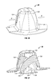
- FIG. 38 is a perspective view of the mandoline slicer of FIG. 1 showing a safety cover in a retracted position.
- FIG. 39 is a perspective view of the mandoline slicer of FIG. 1 showing the safety cover in an intermediate position.
- FIG. 40 is a perspective view of the mandoline slicer of FIG. 1 showing the safety cover in an engaged position.
- FIG. 41 is a perspective view of a leg assembly of the mandoline slicer of FIG. 1 .
- FIG. 42 is a perspective view of the mandoline slicer of FIG. 1 showing the leg assembly in an extended position.
- FIG. 43 is a perspective view of the mandoline slicer of FIG. 1 showing the leg assembly in storage position.
- a mandoline slicer 10 according to a first preferred embodiment of the present invention comprises a frame 12 , generally rectangular in shape, having a pair of opposing, substantially parallel sidewalls 14 , 16 .
- the slicer further includes an infeed plate 18 , a discharge plate 20 , a reversible slicing blade 22 , a cutting knife 24 , an adjustment mechanism 26 and a carriage assembly 28 .
- the adjustment mechanism 26 may be utilized for modifying the thickness of slices resulting from the slicing operation when the food product is guided across the slicer 10 in a cutting direction 30 .
- the carriage assembly 28 may be utilized to grip or hold the food item such that it can be easily and safely moved across the slicer 10 . As best shown in FIG.
- the cutting direction 30 is parallel to the infeed plate 18 and towards the reversible slicing blade 22 .
- Portions of the frame 12 may be formed from any material having sufficient strength for supporting the slicing operation, as known in the art, including but not limited to, metals, plastics and combinations thereof.
- the sidewalls 14 , 16 are interconnected adjacent to a rear end thereof by a handle 32 .
- Respectively integral with the sidewalls 14 , 16 at the front (downstream) ends thereof and extending downwardly and forwardly therefrom are feet 34 .
- a leg assembly 36 is rotatably connected to an inner portion of the opposed sidewalls 14 , 16 at a rear (upstream) end thereof and may fold into a recess of the slicer 10 for more compact storage, as discussed in detail below.
- the infeed plate 18 is generally rectangular in shape, is pivotally attached to the frame 12 at an inner surface of the sidewalls 14 , 16 adjacent the handle 32 , and is dimensioned to fit between the sidewalls 14 , 16 between the handle 32 and the triangular opening 40 .
- the infeed plate has a substantially straight front edge 42 disposed substantially perpendicular to the sidewalls 14 , 16 . Downstream of the front edge 42 of the infeed plate 18 is a generally rectangular opening 44 dimensioned to receive the cutting knife 24 , as shown in FIGS. 7 and 8 , and a generally rectangular opening 46 for receiving the slicing blade 22 , as shown in FIGS. 5 and 6 .
- the discharge plate 20 is also rectangular in shape and occupies the space between the sidewalls 14 , 16 at the forward, downstream end thereof, being fixedly secured thereto by suitable means such as with pins or other means known in the art, or by being integrally formed therewith.
- suitable means such as with pins or other means known in the art, or by being integrally formed therewith.
- One or both of the infeed plate 18 and the discharge plate 20 may be provided with longitudinally extending and laterally spaced apart ribs 48 .
- the reversible slicing blade 22 has an elongated, rectangular generally flat body 50 and is provided at one end thereof with a handle 52 .
- the handle 52 includes a depression 54 formed thereon to facilitate gripping during insertion or removal.
- the other end of the blade 22 is provided with a two-pronged hook 56 for securing the blade, as discussed below.
- the body is preferably formed of metal and defines a first longitudinally extending blade edge 58 along one side thereof and a second blade edge 60 along an opposite side thereof, the second blade edge 60 including a plurality of flutes or serrations 62 .
- the blade 22 is dimensioned to be received in the rectangular opening 38 , as illustrated in FIGS.
- the blade 22 is reversible so that either the first blade edge 58 or the second blade edge 60 may be selectively presented against the cutting direction 30 for slicing a food item.
- each cutting knife 24 , 25 has a rectangular generally flat body 64 and is provided at one end thereof with a handle 66 .
- the handle 66 of the cutting knives 24 , 25 include a depression 68 formed thereon to facilitate gripping during insertion or removal from the frame 12 of the slicer 10 .
- the other end of the knives 24 , 25 is provided with a two-pronged hook 70 for securing the blade to the frame 12 in the manner discussed above.
- the body 64 is preferably formed of metal and has a plurality of generally triangular, vertically extending cutting blades 72 laterally spaced along a length thereof.
- the knives 24 , 25 are dimensioned to be selectively received in the triangular opening 40 , as illustrated in FIGS. 7 and 8 , such that the hook 70 engages the sidewall 16 , whereupon the hook 70 snaps into a corresponding receptacle (not shown) formed in the sidewall 16 .
- the sidewall 14 also includes a pair of auxiliary openings 74 adjacent the forward, distal end thereof.
- the auxiliary openings 74 are preferably the same as opening 40 and function to securely store cutting knives 24 , 25 that are not utilized during the slicing operation.
- one of the cutting knives 24 , 25 may be removed from its stowed position in opening 74 and inserted into opening 40 , as discussed above, to effect a cutting action.
- both cutting knives 24 , 25 may be left in the stowed/secured position such that only a slicing of a food item is achieved.
- the adjustment mechanism 26 for selectively modifying the thickness of slices of a food item is shown.
- the adjustment mechanism 26 includes a semi-annular inner gear 76 slidably mounted within a correspondingly shaped slide rail 78 , and a lever 80 operatively connected to (fixedly attached or integrally formed with) the inner gear 76 for slidably moving the inner gear 76 within the slide rail 78 from a first position to a second position.
- the inner gear 76 and slide rail 78 are received within a semi-annular-shaped recess 82 in the frame 12 and are held in position by a removable cover 84 .
- the cover 84 is secured to the frame 12 using pins or screws, although other means known in the art may also be utilized.
- the adjustment mechanism 26 further includes two screw members 86 having a body portion 88 having a helical thread 90 formed on a surface thereof, and a head portion 92 in the form of a gear integral with the body portion 88 .
- the screw members are received in threaded throughbores 94 provided in the frame 12 on an underside of the slicer 10 .
- the throughbores 94 are located adjacent to the wall of the recess 82 such that when the screw members 86 are received in the throughbores 94 , the geared head portion 92 of the screw member 86 meshes with the inner gear 76 so that the inner gear 76 can drive the screw members 86 , as discussed in detail below. While the figures show the mandoline slicer 10 as having a pair of screw members 86 , more or fewer screw members 86 may be utilized without departing from the broader aspects of the present invention.
- a rearward portion of the infeed plate 18 is pivotally mounted about a shaft or protrusion 96 adjacent to the handle 32 .
- the opposing, forward portion of the infeed plate 18 , adjacent to the slicing blade 22 is free to move up or down, as discussed in detail below, and is limited in its downward movement by contact with distal ends 98 of the screw members 86 .
- a portion of the frame 12 is provided with visual increments 100 corresponding to an array of predetermined slice thicknesses.
- the lever 80 is configured for selective movement along an arcuate path in the direction of arrow A to adjust slice thickness, as hereinafter discussed.
- the lever 80 is shown as being in a first position, corresponding to “0” inch thickness as denoted by the visual increments 100 .
- the inner gear 76 is at the position shown in FIGS. 18 and 19 and the screw members 86 are at a fully advanced position such that the gear head portion 92 of the screw members 86 meshes/engages the inner gear 76 at an inner portion thereof.
- FIGS. 16 and 17 the lever 80 is shown as being in a first position, corresponding to “0” inch thickness as denoted by the visual increments 100 .
- the inner gear 76 is at the position shown in FIGS. 18 and 19 and the screw members 86 are at a fully advanced position such that the gear head portion 92 of the screw members 86 meshes/engages the inner gear 76 at an inner portion thereof.
- the screw members 86 are fully advanced such that the distal ends 98 of the screw members 86 hold the infeed plate 18 (in particular, the forward portion of the infeed plate 18 ) in a position substantially coplanar with the slicing blade 22 and the discharge plate 20 .
- the infeed plate 18 being substantially aligned (coplanar) with the slicing blade 22 , translation of a food item in the cutting direction 30 will not slice the item.
- This rotation causes the screw members 86 , by way of their threaded engagement with the throughbores 94 , to retract and travel up the inner gear 76 to a fully retracted position such that the gear head portion 92 of the screw members 86 meshes/engages the inner gear 76 at an outer portion thereof.
- the screw members 86 are fully retracted such that the distal ends 98 of the screw members 86 hold the infeed plate 18 (in particular, the forward portion of the infeed plate 18 ) in a position below the edge 58 or 60 , of the slicing blade 22 .
- the infeed plate 18 is no longer coplanar or parallel with the slicing blade.
- the screw members 86 retract in the throughbores 94 from the position shown in FIGS. 20 and 21 to the position shown in FIGS. 26 and 27 , causing the infeed plate 18 rotate downwardly about shaft 96 so that a clearance is provided, in the vertical direction, between the front edge 42 of the infeed plate 18 and the edge 58 or 60 of the slicing blade 22 .
- the lever 80 can be positioned at the zero thickness and maximum thickness positions, it will be readily appreciated that the lever 80 may can also be selectively oriented at a position anywhere in between the zero and maximum thickness positions to produce slices of a food item having a thickness anywhere between zero thickness and maximum thickness.
- the maximum thickness is 1 ⁇ 3′′, however the slicer 10 may be modified to provide for greater slice thicknesses without departing from the broader aspects of the present invention.
- a user moves the lever 80 in the opposite direction described above, i.e., in the opposite direction of arrow A.
- This causes the inner gear 76 to rotate clockwise (when viewed from the bottom of the slicer 10 ) which, in turn, causes the screw members 86 to rotate in the same direction.
- This rotation causes the screw members 86 to advance within the threaded throughbores 94 such that the distal ends 98 of the screw members 86 exert a force on the underside of the infeed plate 18 , causing it to rotate in an upwards direction about shaft 96 to decrease the vertical clearance between the front edge 42 of the infeed plate 18 and the edge 58 or 60 of the slicing blade 22 .
- the carriage assembly 28 for gripping or holding the food item such that it can be easily and safely moved across the slicer 10 .
- the carriage assembly 28 includes a housing 102 , a pair of pushbuttons 104 rotatably mounted about a shaft 105 in apertures on opposing sides of the housing 102 and a food press plate 106 mounted on a plurality of guide pins 108 and disposed within the housing 102 .
- the pushbuttons 104 are generally C-shaped in cross-section and have a first portion 110 , a second portion 112 integrally formed with and extending generally perpendicular from the first portion 110 and a third, contact portion 114 integrally formed with and extending generally perpendicular from the second portion 112 .
- guide pins 108 are fixedly attached to the housing 102 and are oriented substantially vertically.
- the press plate 106 is slidably mounted on the guide pins 108 and includes a plurality of food gripping members 116 for gripping a food item.
- the carriage assembly 28 is shown in a non-gripping position.
- the press plate 106 is in a retracted position within the housing and the pushbuttons 104 are biased outwards.
- the third, contact portion 114 of the pushbuttons 104 exerts a generally downward force on a top side of the press plate 106 .
- This force urges the press plate 106 to slide along the guide pins 108 in the direction of arrow D and out of the housing 102 such that the press plate 106 and gripping members 116 engage a food item.
- the press plate releases 106 the food item and retracts along the guide pins 108 into the housing 102 .
- carriage assemblies require a user to exert a downward force upon the assembly to engage a food item. This is dangerous, as a users hand may slip off the assembly and across the slicing blade, causing injury.
- the carriage assembly 28 of the mandoline slicer 10 of the present invention does not require a user to exert a downward force with his or her hand but instead simply requires a user to press pushbuttons 104 inward to actuate the press plate 106 , thereby decreasing the likelihood that a user's hand will slip off the carriage assembly and into the slicing blade.
- the mandoline slicer of the present invention may also include a safety cover 118 .
- the safety cover 118 is pivotally attached to the frame 12 at an inner surface of the sidewalls 14 , 16 adjacent the slicing blade 22 and is dimensioned to fit between the sidewalls 14 , 16 downstream from the slicing blade 22 .
- the safety cover 118 is shown in an open, cutting position in FIG. 38 .
- the cover 116 has a plurality of generally longitudinal and spaced apart ribs on one surface thereof.
- a user grips protrusion 120 on the safety cover 118 and rotates the safety cover in the direction of the arrows such that the safety cover 116 blocks the slicing blade 22 and cutting knives 24 , 25 , as shown in FIG. 40 .
- the safety cover 116 provides added protection against injury when the slicer 10 is not in use.
- the leg assembly 36 includes a pair of leg members 122 having feet 124 substantially similar to feet 34 .
- the leg members 36 are integrally formed with a hook portion 126 to facilitate easy activation and are fixedly mounted on opposing ends of an axle 128 .
- the leg assembly 36 is pivotally attached to the frame 12 at an inner surface of the sidewalls 14 , 16 underneath the infeed plate 18 and adjacent the handle 32 .
- the leg assembly 36 is rotatable from the open position shown in FIG. 42 , to the stowed position shown in FIG. 43 wherein the leg assembly 36 is folded into a recess in the frame. In order to open the leg assembly 36 , a user must simply grab hook portion 126 and pull in the direction of the arrow shown in FIG. 43 .
Landscapes
- Engineering & Computer Science (AREA)
- Mechanical Engineering (AREA)
- Life Sciences & Earth Sciences (AREA)
- Forests & Forestry (AREA)
- Food Science & Technology (AREA)
- Food-Manufacturing Devices (AREA)
Abstract
Description
Claims (4)
Priority Applications (3)
| Application Number | Priority Date | Filing Date | Title |
|---|---|---|---|
| US13/042,050 US8893602B2 (en) | 2011-03-07 | 2011-03-07 | Mandoline slicer |
| CA2767647A CA2767647C (en) | 2011-03-07 | 2012-02-10 | Mandoline slicer |
| EP20120156820 EP2497400B1 (en) | 2011-03-07 | 2012-02-24 | Mandoline slicer |
Applications Claiming Priority (1)
| Application Number | Priority Date | Filing Date | Title |
|---|---|---|---|
| US13/042,050 US8893602B2 (en) | 2011-03-07 | 2011-03-07 | Mandoline slicer |
Publications (2)
| Publication Number | Publication Date |
|---|---|
| US20120227564A1 US20120227564A1 (en) | 2012-09-13 |
| US8893602B2 true US8893602B2 (en) | 2014-11-25 |
Family
ID=45656619
Family Applications (1)
| Application Number | Title | Priority Date | Filing Date |
|---|---|---|---|
| US13/042,050 Active 2033-05-10 US8893602B2 (en) | 2011-03-07 | 2011-03-07 | Mandoline slicer |
Country Status (3)
| Country | Link |
|---|---|
| US (1) | US8893602B2 (en) |
| EP (1) | EP2497400B1 (en) |
| CA (1) | CA2767647C (en) |
Cited By (6)
| Publication number | Priority date | Publication date | Assignee | Title |
|---|---|---|---|---|
| US20150246457A1 (en) * | 2014-02-28 | 2015-09-03 | King's Flair Development Ltd. | Mandolin slicer |
| US9296115B2 (en) * | 2014-04-18 | 2016-03-29 | King's Flair Development Ltd. | Cheese slicer |
| US20160101535A1 (en) * | 2014-10-08 | 2016-04-14 | John L. Schoeman | Dual Thickness Food Slicer |
| US10035280B2 (en) | 2014-02-28 | 2018-07-31 | King's Flair Development Ltd. | Mandolin slicer |
| USD862170S1 (en) * | 2018-02-28 | 2019-10-08 | Progressive International Corporation | Spiral cutting insert |
| US10779684B2 (en) * | 2019-01-29 | 2020-09-22 | Polymerography, Llc | Linear herb grinder |
Families Citing this family (27)
| Publication number | Priority date | Publication date | Assignee | Title |
|---|---|---|---|---|
| US10160133B2 (en) | 2011-02-08 | 2018-12-25 | Progressive International Corporation | Mandoline slicer |
| US9682490B2 (en) | 2011-02-08 | 2017-06-20 | Progressive International Corporation | Mandoline slicer |
| USD734107S1 (en) * | 2011-11-17 | 2015-07-14 | Dkb Household Uk Limited | Handheld slicer with hand guard |
| USD751352S1 (en) * | 2012-07-20 | 2016-03-15 | Kai R & D Center Co., Ltd. | Slicer |
| EP3082532B1 (en) * | 2013-12-20 | 2018-08-15 | Fissler GmbH | Grater |
| IL234352B (en) * | 2014-02-04 | 2019-02-28 | Progressive Int Corp | Mandoline slicer |
| USD752388S1 (en) * | 2014-06-25 | 2016-03-29 | Masterful Limited | Food slicer hand guard |
| JP6007210B2 (en) * | 2014-06-30 | 2016-10-12 | 株式会社ベンリナー | Slicer |
| US9821483B2 (en) * | 2015-07-24 | 2017-11-21 | Helen Of Troy Limited | Mandoline-type food slicer |
| JP6411303B2 (en) * | 2015-09-08 | 2018-10-24 | 株式会社ベンリナー | Slicer |
| USD829513S1 (en) * | 2016-02-22 | 2018-10-02 | Dkb Household Uk Limited | Food slicer |
| CA2998346A1 (en) * | 2017-03-16 | 2018-09-16 | Progressive International Corporation | Mandoline with spiralizer insert |
| CN107363901B (en) * | 2017-08-28 | 2023-06-23 | 马鞍山联洪合成材料有限公司 | Hot-melt type damping sheet punching and cutting device and punching method thereof |
| CN107471266B (en) * | 2017-09-25 | 2023-09-08 | 湖南君旺机械设备有限公司 | Safe adjustable cutting machine |
| US10478986B2 (en) * | 2017-10-12 | 2019-11-19 | Masterful Limited | Mandoline slicer |
| US11278146B2 (en) * | 2018-01-30 | 2022-03-22 | Progressive International Corporation | Apple parer |
| CN208841513U (en) * | 2018-07-19 | 2019-05-10 | 陈篇 | A kind of water melon knife |
| CN114161497A (en) * | 2018-08-10 | 2022-03-11 | 宁波金舜家居用品有限公司 | Food cutter |
| CN109773838B (en) * | 2019-01-28 | 2021-06-08 | 孟开仁 | Push type hand protector ware |
| CN109719762B (en) * | 2019-01-28 | 2021-06-15 | 孟开仁 | A vegetable cutter with a push-type hand guard |
| CN110000827A (en) * | 2019-04-16 | 2019-07-12 | 江苏信息职业技术学院 | A kind of fruits and vegetables auto slice device |
| USD994442S1 (en) * | 2021-03-26 | 2023-08-08 | Fujian Meizhikou Houseware Co., Ltd. | Veggie chopper |
| USD995232S1 (en) * | 2021-06-23 | 2023-08-15 | Guixing Ke | Slicer |
| USD1007972S1 (en) * | 2021-06-23 | 2023-12-19 | Guixing Ke | Slicer |
| USD992980S1 (en) | 2021-09-14 | 2023-07-25 | Progressive International Corp. | Mandoline |
| CN115008536A (en) * | 2022-05-19 | 2022-09-06 | 刘辉 | Multi-functional hydraulic pressure chinese angelica slicer |
| USD1052362S1 (en) | 2022-10-24 | 2024-11-26 | Progressive International Corp. | Mandoline |
Citations (6)
| Publication number | Priority date | Publication date | Assignee | Title |
|---|---|---|---|---|
| US4273013A (en) * | 1979-07-09 | 1981-06-16 | Sunbeam Corporation | Slicing machine |
| US7107890B2 (en) | 2001-05-28 | 2006-09-19 | De Buyer | Safety manual vegetable cutter |
| US7143677B2 (en) | 2003-05-01 | 2006-12-05 | Helen Of Troy Limited | Food slicer |
| US20060283299A1 (en) * | 2005-06-16 | 2006-12-21 | Design For Living, L.L.C. | Food slicer with suction device and adjustable cutting surface |
| US20070125207A1 (en) | 2005-12-06 | 2007-06-07 | Kai U.S.A. Ltd., Dba Kershaw Knives | Mandolin slicer |
| US7621207B2 (en) | 2005-12-16 | 2009-11-24 | Dkb Household Usa Corp. | Adjustable slicing device |
Family Cites Families (3)
| Publication number | Priority date | Publication date | Assignee | Title |
|---|---|---|---|---|
| DE102007007308B4 (en) * | 2007-02-07 | 2013-10-24 | Börner Kunststoff- und Metallwarenfabrik GmbH | slicer |
| DE202008002233U1 (en) * | 2008-02-18 | 2008-06-12 | Repac, Cedomir | slicer |
| US8430010B2 (en) * | 2008-11-19 | 2013-04-30 | Progressive International Corporation | Hand held slicer |
-
2011
- 2011-03-07 US US13/042,050 patent/US8893602B2/en active Active
-
2012
- 2012-02-10 CA CA2767647A patent/CA2767647C/en active Active
- 2012-02-24 EP EP20120156820 patent/EP2497400B1/en active Active
Patent Citations (6)
| Publication number | Priority date | Publication date | Assignee | Title |
|---|---|---|---|---|
| US4273013A (en) * | 1979-07-09 | 1981-06-16 | Sunbeam Corporation | Slicing machine |
| US7107890B2 (en) | 2001-05-28 | 2006-09-19 | De Buyer | Safety manual vegetable cutter |
| US7143677B2 (en) | 2003-05-01 | 2006-12-05 | Helen Of Troy Limited | Food slicer |
| US20060283299A1 (en) * | 2005-06-16 | 2006-12-21 | Design For Living, L.L.C. | Food slicer with suction device and adjustable cutting surface |
| US20070125207A1 (en) | 2005-12-06 | 2007-06-07 | Kai U.S.A. Ltd., Dba Kershaw Knives | Mandolin slicer |
| US7621207B2 (en) | 2005-12-16 | 2009-11-24 | Dkb Household Usa Corp. | Adjustable slicing device |
Cited By (7)
| Publication number | Priority date | Publication date | Assignee | Title |
|---|---|---|---|---|
| US20150246457A1 (en) * | 2014-02-28 | 2015-09-03 | King's Flair Development Ltd. | Mandolin slicer |
| US9446530B2 (en) * | 2014-02-28 | 2016-09-20 | King's Flair Development Ltd. | Mandolin slicer |
| US10035280B2 (en) | 2014-02-28 | 2018-07-31 | King's Flair Development Ltd. | Mandolin slicer |
| US9296115B2 (en) * | 2014-04-18 | 2016-03-29 | King's Flair Development Ltd. | Cheese slicer |
| US20160101535A1 (en) * | 2014-10-08 | 2016-04-14 | John L. Schoeman | Dual Thickness Food Slicer |
| USD862170S1 (en) * | 2018-02-28 | 2019-10-08 | Progressive International Corporation | Spiral cutting insert |
| US10779684B2 (en) * | 2019-01-29 | 2020-09-22 | Polymerography, Llc | Linear herb grinder |
Also Published As
| Publication number | Publication date |
|---|---|
| CA2767647C (en) | 2016-05-31 |
| US20120227564A1 (en) | 2012-09-13 |
| EP2497400A1 (en) | 2012-09-12 |
| EP2497400B1 (en) | 2013-10-16 |
| CA2767647A1 (en) | 2012-09-07 |
Similar Documents
| Publication | Publication Date | Title |
|---|---|---|
| US8893602B2 (en) | Mandoline slicer | |
| US9038517B2 (en) | Mandolin slicer | |
| US12213489B2 (en) | Adjustable thickness sheeting device for a food processing device | |
| US5662033A (en) | Food cutting device | |
| EP3213892B1 (en) | A food holder for a food slicer, and a food slicer | |
| JP5826974B2 (en) | Mandolin slicer | |
| CA2987957C (en) | Mandoline-type food slicer | |
| US20060081108A1 (en) | Manual safety vegetable cutter | |
| KR20140069161A (en) | Handheld kitchen utensil | |
| EP1955628A1 (en) | Food Slicer and Grater | |
| CA2158311C (en) | Cheese slicer | |
| US10137588B1 (en) | Utility cutter | |
| US20060207403A1 (en) | Bagel sandwich knife | |
| FR3034035A1 (en) | SLICER FOR SANDWICHES | |
| US20220226915A1 (en) | A folding hacksaw | |
| EP3470187B1 (en) | Mandoline slicer | |
| US20230011787A1 (en) | Adjustable knife guide assembly | |
| KR20260056438A (en) | Food material double-ended fixed slicer | |
| US20160101535A1 (en) | Dual Thickness Food Slicer | |
| CN216776818U (en) | Sliding distance-adjustable combined seat for cutting tools and chopping boards | |
| KR101024682B1 (en) | Multifunctional Kitchen Slicer | |
| JP5288630B2 (en) | Guillotine type manual cutter | |
| RU115183U1 (en) | GRINDING DEVICE | |
| HK1205717B (en) | Mandoline slicer |
Legal Events
| Date | Code | Title | Description |
|---|---|---|---|
| AS | Assignment |
Owner name: CONAIR CORPORATION, CONNECTICUT Free format text: ASSIGNMENT OF ASSIGNORS INTEREST;ASSIGNOR:FUNG, KAM FAI;REEL/FRAME:025918/0808 Effective date: 20110304 |
|
| STCF | Information on status: patent grant |
Free format text: PATENTED CASE |
|
| MAFP | Maintenance fee payment |
Free format text: PAYMENT OF MAINTENANCE FEE, 4TH YEAR, LARGE ENTITY (ORIGINAL EVENT CODE: M1551) Year of fee payment: 4 |
|
| AS | Assignment |
Owner name: CONAIR LLC, CONNECTICUT Free format text: ASSIGNMENT OF ASSIGNORS INTEREST;ASSIGNOR:CONAIR CORPORATION;REEL/FRAME:057216/0011 Effective date: 20210512 |
|
| AS | Assignment |
Owner name: OWL ROCK CAPITAL CORPORATION, AS ADMINISTRATIVE AGENT, NEW YORK Free format text: SECURITY INTEREST;ASSIGNOR:CONAIR LLC;REEL/FRAME:056336/0098 Effective date: 20210517 Owner name: BANK OF AMERICA, N.A., AS ADMINISTRATIVE AGENT, NORTH CAROLINA Free format text: SECURITY INTEREST;ASSIGNOR:CONAIR LLC;REEL/FRAME:056336/0166 Effective date: 20210517 Owner name: BANK OF AMERICA, N.A., AS ADMINISTRATIVE AGENT, NORTH CAROLINA Free format text: SECURITY INTEREST;ASSIGNOR:CONAIR LLC;REEL/FRAME:056336/0230 Effective date: 20210517 |
|
| MAFP | Maintenance fee payment |
Free format text: PAYMENT OF MAINTENANCE FEE, 8TH YEAR, LARGE ENTITY (ORIGINAL EVENT CODE: M1552); ENTITY STATUS OF PATENT OWNER: LARGE ENTITY Year of fee payment: 8 |