US8891735B2 - Auto grid moving device for diagnostic X ray table - Google Patents
Auto grid moving device for diagnostic X ray table Download PDFInfo
- Publication number
- US8891735B2 US8891735B2 US13/436,842 US201213436842A US8891735B2 US 8891735 B2 US8891735 B2 US 8891735B2 US 201213436842 A US201213436842 A US 201213436842A US 8891735 B2 US8891735 B2 US 8891735B2
- Authority
- US
- United States
- Prior art keywords
- grid
- ray
- holder
- timing belt
- timing
- Prior art date
- Legal status (The legal status is an assumption and is not a legal conclusion. Google has not performed a legal analysis and makes no representation as to the accuracy of the status listed.)
- Expired - Fee Related, expires
Links
Images


Classifications
-
- A—HUMAN NECESSITIES
- A61—MEDICAL OR VETERINARY SCIENCE; HYGIENE
- A61B—DIAGNOSIS; SURGERY; IDENTIFICATION
- A61B6/00—Apparatus for radiation diagnosis, e.g. combined with radiation therapy equipment
- A61B6/58—Testing, adjusting or calibrating apparatus or devices for radiation diagnosis
- A61B6/582—Calibration
- A61B6/583—Calibration using calibration phantoms
-
- A61B6/0457—
-
- A—HUMAN NECESSITIES
- A61—MEDICAL OR VETERINARY SCIENCE; HYGIENE
- A61B—DIAGNOSIS; SURGERY; IDENTIFICATION
- A61B6/00—Apparatus for radiation diagnosis, e.g. combined with radiation therapy equipment
- A61B6/04—Positioning of patients; Tiltable beds or the like
- A61B6/0487—Motor-assisted positioning
-
- A—HUMAN NECESSITIES
- A61—MEDICAL OR VETERINARY SCIENCE; HYGIENE
- A61B—DIAGNOSIS; SURGERY; IDENTIFICATION
- A61B6/00—Apparatus for radiation diagnosis, e.g. combined with radiation therapy equipment
- A61B6/42—Apparatus for radiation diagnosis, e.g. combined with radiation therapy equipment with arrangements for detecting radiation specially adapted for radiation diagnosis
- A61B6/4291—Apparatus for radiation diagnosis, e.g. combined with radiation therapy equipment with arrangements for detecting radiation specially adapted for radiation diagnosis the detector being combined with a grid or grating
Definitions
- the field of the invention relates to the configuration of a grid for an X ray imaging device.
- the grid for an X ray imaging device is generally mountable onto an X ray detector housing, from which the operator can push in or pull out the grid as needed.
- the operator has to pull out the grid from the detector housing of the X ray imaging device bed for pediatric and extremity X ray inspections; and push back in for other X ray inspections.
- This configuration and operation suffers from several deficiencies.
- the operator may sometimes have difficulty pushing in or pulling out the grid as a result of not being able to locate the grid-in slot when performing such operation.
- the operation of this configuration is also time consuming.
- a grid docking device takes up space. Furthermore, frequent pushing in and pushing out of the grid may cause damage.
- an auto grid moving apparatus is provided.
- the grid can move in the area of X ray detector automatically, and can be driven automatically according to X ray exposure exam parameters, thereby replacing the aforementioned manual pushing in and out operation of the grid.
- an auto grid moving apparatus for an X ray imaging device.
- the apparatus includes: a grid; a grid holder on which the grid is disposed; a fixing base; and a double sided timing belt geared with at least two timing wheels at the two ends of the timing belt on the inner side face of the timing belt and geared with the grid holder at the outer side face of the timing belt, wherein one of the timing wheels has a motor disposed thereon, the motor being configured to drive the timing wheel to move the timing belt and to drive the grid holder to move.
- a bed of an X ray imaging device includes: a table; an X ray detector holder housing disposed beneath the table; table frames at two ends of the table; and an auto grid moving apparatus located between the underneath of the table and the X ray detector holder housing.
- the auto grid moving apparatus includes: a grid; a grid holder on which the grid is disposed; a fixing base fixed beneath the table; and a double sided timing belt geared with at least two timing wheels at the two ends of the timing belt on the inner side face of the timing belt and geared with the grid holder at the outer side face of the timing belt, wherein one of the timing wheels has a motor disposed thereon, the motor being configured to drive the timing wheel to move the timing belt and to drive the grid holder to move.
- the auto grid moving apparatus is configured to drive the grid back and forth between the X ray detector housing and the table
- an X ray imaging device includes an auto grid moving apparatus that includes: a grid; a grid holder on which the grid is disposed; a fixing base; and a double sided timing belt geared with at least two timing wheels at the two ends of the timing belt on the inner side face of the timing belt and geared with the grid holder at the outer side face of the timing belt, wherein one of the timing wheels has a motor disposed thereon, the motor being configured to drive the timing wheel to move the timing belt and to drive the grid holder to move.
- FIG. 1 shows a front view and top view of an auto grid moving apparatus according to an embodiment of the present invention
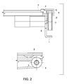
- FIG. 2 shows a left side view of the auto grid moving apparatus and a front view of the semi-circular timing wheel part thereof according to an embodiment of the present invention
- FIG. 3 shows a schematic view of the movement of the auto grid moving apparatus according to an embodiment of the present invention.
- FIG. 4 shows a support configuration of the auto grid moving apparatus according to an embodiment of the present invention.
- FIG. 1 shows the front view (top of FIG. 1 ) and top view (bottom of FIG. 1 ) of an auto grid moving apparatus.
- the auto grid moving apparatus is located beneath a table 8 .
- a grid 7 is driven by the auto grid moving apparatus and is able to move back and forth between the table 8 and an ion chamber 6 beneath the table 8 .
- the apparatus makes use of a double sided timing belt 2 .
- the timing belt 2 gears with two timing wheels 1 and 3 at two ends of its inner side face, wherein a motor is disposed on one of the timing wheels 1 to drive the timing belt 2 .
- the outer side face of the timing belt 2 also gears with a grid holder 4 and another three semi-circular timing wheels 5 are fixed on the grid holder 4 .
- the motor drives the timing wheel 1 , thereby moving the timing belt 2 to drive the grid holder 4 to move towards the same direction.
- the grid holder 4 in turn moves the grid 7 .
- the range of the movement can be triple the distance between the two timing wheels 1 and 3 (refer to top view).
- FIG. 2 shows the left side view of the auto grid moving apparatus and the front view of the semi-circular timing wheel part thereof.
- the double sided timing belt 2 is driven by the motor 9 disposed on the timing wheel 3 at one end thereof, thereby driving the timing wheel 3 at the other end to rotate. Meanwhile the teeth on the timing belt 2 engage with the semi-circular timing wheels 5 on the grid holder 4 , and the movement of the timing belt 2 moves the gird holder 4 attached to the semi-circular timing wheels 5 through the semi-circular timing wheels 5 .
- a guide rail 8 is disposed adjacent to the double sided timing belt 2 to constrain the moving direction of the grid holder 4 .
- the guide rail 8 constrains to the grid holder 4 at its upward, downward, leftward and rightward directions, thereby the grid holder 4 can only move in the forward and backward directions followed with the timing belt 2 .
- the guide rail 8 is fixed to the base 10 of the auto grid moving apparatus.
- FIG. 3 shows the schematic view of the movement of the auto grid moving apparatus.
- the three drawings from top to bottom show the grid 7 moves to the left, center and right positions respectively, wherein the center position refers to a position that the grid 7 covers the area of the X ray detector (or the ion chamber 6 ).
- the double sided timing belt 2 drives the grid holder 4 to move towards the right side, and keeps engaged with all of the three semi-circular timing wheels 5 on the grid holder 4 (the three semi-circular timing wheels corresponds to the left, center and right positions respectively in FIG. 3 ).
- the double sided timing belt 2 drives the grid holder 4 to move towards the right or left side, and keeps engaged with at least one of the three semi-circular timing wheels 5 on the grid holder 4 (the positions of the three semi-circular timing wheels 5 are shown in FIGS. 1 and 2 ).
- the number of the semi-circular timing wheels 5 in engagement is determined by the length of the moving space of the auto grid moving apparatus left in the longitudinal direction of the bed of the X ray imaging device.
- a sliding grid support slider 12 is arranged to provide support for the grid 4 at the non-driving end (opposite to the driving end).
- the grid 7 is attached to a fixing plate 11 at the non-driving end, and support is provided by a guide rail base 13 at the non-driving end.
- the guide rail base 13 provides support to the grid 7 in a vertical direction when the grid 7 moves to the left or right side, so as to prevent the deformation of the grid holder 4 or the sliding grid support slider 12 caused by bending moment of the cantilever due to gravity.
- the sliding grid support slider 12 may partially protrude out of the guide rail base 13 . Because the auto grid moving apparatus is mounted on the X ray detector housing, the X ray detector housing will be blocked by the table frame and automatically restore position when it reaches the end of the table.
- FIG. 4 shows the support configuration of the auto grid moving apparatus.
- the grid holder 4 (refer to FIG. 2 ) is located above the guide rail base 13 at the driving end portion, and is supported by the sliding grid support slider 12 at the non-driving end.
- the sliding grid support slider 12 can move bi-directionally, and forms support to the grid 7 .
- there is a hard stopper at each of the two ends of the sliding support slider 12 cooperating with screw/bolt 15 on the guide rail base 13 , the sliding support slider 12 always moves along the guide rail base 13 and protrudes at most half of its length, without getting detached.
- a screw/bolt 14 or a support block is provided at the middle portion of the sliding grid support slider 12 , in the partial views E and F, the fixing plate 11 at the non-driving end has a hook at each of its two ends.
- the hook (screw/bolt) at one end will contact with the screw/bolt or the support block at the middle portion of the sliding grid support slider 12 , pushing the sliding grid support slider 12 to slide on the guide rail base 13 , thereby making sure at least half of the grid 7 is supported by the sliding grid support slider 12 when the grid 7 moves out of the imaging area completely.
- the auto grid moving apparatus disclosed herein is applicable in an X ray imaging device, and further in other medical imaging diagnostic devices that require plug/pull or mount/unmount of the grid.
- Embodiments of the present invention solve the problem that the operator has to manually pull out and push in the grid, which thereby facilitates the work of the operator.
- the auto grid moving apparatus also cancels the grid dock. Therefore, the structure is more compact and more reliable.
- the X ray imaging device can achieve automatic mounting and unmounting of the grid with the control of the exposure parameters, thereby improving the efficiency of X ray inspection.
Landscapes
- Health & Medical Sciences (AREA)
- Life Sciences & Earth Sciences (AREA)
- Medical Informatics (AREA)
- Engineering & Computer Science (AREA)
- Radiology & Medical Imaging (AREA)
- Biomedical Technology (AREA)
- Biophysics (AREA)
- Nuclear Medicine, Radiotherapy & Molecular Imaging (AREA)
- Optics & Photonics (AREA)
- Pathology (AREA)
- Physics & Mathematics (AREA)
- High Energy & Nuclear Physics (AREA)
- Heart & Thoracic Surgery (AREA)
- Molecular Biology (AREA)
- Surgery (AREA)
- Animal Behavior & Ethology (AREA)
- General Health & Medical Sciences (AREA)
- Public Health (AREA)
- Veterinary Medicine (AREA)
- Apparatus For Radiation Diagnosis (AREA)
Abstract
Description
Claims (13)
Applications Claiming Priority (3)
| Application Number | Priority Date | Filing Date | Title |
|---|---|---|---|
| CN201110096091 | 2011-03-31 | ||
| CN201110096091.XA CN102727242B (en) | 2011-03-31 | 2011-03-31 | X ray image equipment grid automatic drive |
| CN201110096091.X | 2011-03-31 |
Publications (2)
| Publication Number | Publication Date |
|---|---|
| US20120275570A1 US20120275570A1 (en) | 2012-11-01 |
| US8891735B2 true US8891735B2 (en) | 2014-11-18 |
Family
ID=46984050
Family Applications (1)
| Application Number | Title | Priority Date | Filing Date |
|---|---|---|---|
| US13/436,842 Expired - Fee Related US8891735B2 (en) | 2011-03-31 | 2012-03-31 | Auto grid moving device for diagnostic X ray table |
Country Status (2)
| Country | Link |
|---|---|
| US (1) | US8891735B2 (en) |
| CN (1) | CN102727242B (en) |
Cited By (2)
| Publication number | Priority date | Publication date | Assignee | Title |
|---|---|---|---|---|
| US10238352B2 (en) | 2015-06-02 | 2019-03-26 | Siemens Healthcare Gmbh | Recording X-ray images without scattered radiation |
| US20210236074A1 (en) * | 2020-01-30 | 2021-08-05 | Canon Medical Systems Corporation | X-ray diagnostic apparatus and scattered-ray removing device |
Families Citing this family (5)
| Publication number | Priority date | Publication date | Assignee | Title |
|---|---|---|---|---|
| CN103892849B (en) * | 2012-12-27 | 2016-02-10 | 深圳市蓝韵实业有限公司 | Grid storage device |
| CN103976752B (en) * | 2014-05-05 | 2016-09-21 | 杨开彬 | Mammary machine grid driver |
| WO2016142824A1 (en) * | 2015-03-06 | 2016-09-15 | Ecole Polytechnique Federale De Lausanne (Epfl) | Medical detector and antidiffusion grid for medical imaging device |
| KR102137764B1 (en) * | 2018-06-12 | 2020-07-24 | 연세대학교 산학협력단 | Single Source Cone Beam Computed Tomography System Operating in Dual Energy Mode Using Binary Moving Modulation Blocker |
| JP2022092421A (en) * | 2020-12-10 | 2022-06-22 | キヤノンメディカルシステムズ株式会社 | X-ray diagnostic apparatus |
Citations (6)
| Publication number | Priority date | Publication date | Assignee | Title |
|---|---|---|---|---|
| US2767323A (en) * | 1951-07-21 | 1956-10-16 | Picker X Ray Corp Waite Mfg | X-ray grid actuating device |
| US4118116A (en) * | 1977-06-20 | 1978-10-03 | Hipoint Research, Inc. | X-ray processing system |
| US4542521A (en) * | 1982-09-29 | 1985-09-17 | Siemens Aktiengesellschaft | Radiographic installation for an x-ray examination apparatus |
| US5402462A (en) * | 1992-01-31 | 1995-03-28 | Kabushiki Kaisha Toshiba | X-ray CT scanner |
| JP2001154299A (en) * | 1999-11-29 | 2001-06-08 | Canon Inc | Radiation image photographing device |
| US20010022833A1 (en) * | 1999-12-24 | 2001-09-20 | Masaaki Kobayashi | Radiographic apparatus, radiographic table and radiographic system |
-
2011
- 2011-03-31 CN CN201110096091.XA patent/CN102727242B/en not_active Expired - Fee Related
-
2012
- 2012-03-31 US US13/436,842 patent/US8891735B2/en not_active Expired - Fee Related
Patent Citations (6)
| Publication number | Priority date | Publication date | Assignee | Title |
|---|---|---|---|---|
| US2767323A (en) * | 1951-07-21 | 1956-10-16 | Picker X Ray Corp Waite Mfg | X-ray grid actuating device |
| US4118116A (en) * | 1977-06-20 | 1978-10-03 | Hipoint Research, Inc. | X-ray processing system |
| US4542521A (en) * | 1982-09-29 | 1985-09-17 | Siemens Aktiengesellschaft | Radiographic installation for an x-ray examination apparatus |
| US5402462A (en) * | 1992-01-31 | 1995-03-28 | Kabushiki Kaisha Toshiba | X-ray CT scanner |
| JP2001154299A (en) * | 1999-11-29 | 2001-06-08 | Canon Inc | Radiation image photographing device |
| US20010022833A1 (en) * | 1999-12-24 | 2001-09-20 | Masaaki Kobayashi | Radiographic apparatus, radiographic table and radiographic system |
Cited By (3)
| Publication number | Priority date | Publication date | Assignee | Title |
|---|---|---|---|---|
| US10238352B2 (en) | 2015-06-02 | 2019-03-26 | Siemens Healthcare Gmbh | Recording X-ray images without scattered radiation |
| US20210236074A1 (en) * | 2020-01-30 | 2021-08-05 | Canon Medical Systems Corporation | X-ray diagnostic apparatus and scattered-ray removing device |
| US11744533B2 (en) * | 2020-01-30 | 2023-09-05 | Canon Medical Systems Corporation | X-ray diagnostic apparatus and scattered-ray removing device |
Also Published As
| Publication number | Publication date |
|---|---|
| US20120275570A1 (en) | 2012-11-01 |
| CN102727242B (en) | 2016-08-24 |
| CN102727242A (en) | 2012-10-17 |
Similar Documents
| Publication | Publication Date | Title |
|---|---|---|
| US8891735B2 (en) | Auto grid moving device for diagnostic X ray table | |
| CN104967039A (en) | Electric power drawer cabinet device capable of pushing out under automatic control | |
| JP5897924B2 (en) | Battery replacement robot | |
| CN103561657B (en) | Sleeping berth device and function image/morphological image diagnostic equipment | |
| CN104836142A (en) | Power drawer device with noise reduction function | |
| CN104852315A (en) | Electric drawer cabinet apparatus with cooperation between slide blocks and chutes | |
| CN104967040A (en) | Electric power drawer cabinet device with stop block and under guidance of guide rod | |
| CN111687802A (en) | Automatic assembling equipment for dish washing machine panel | |
| CN104853571A (en) | Electric power drawer cabinet apparatus with heat dissipation function | |
| CN104836145A (en) | Automatic control-pushed and noise reduction power drawer device | |
| CN104852320A (en) | Electric drawer device employing contact sensor | |
| US10314552B2 (en) | Bed apparatus and X-ray computed tomography apparatus | |
| CN104967038A (en) | Speed adjustable electric power drawer cabinet device | |
| CN105006765B (en) | The electric power drawer cabinet device that a kind of automatic control advances and can dispel the heat | |
| CN113362657B (en) | Multimedia teaching device for teaching | |
| CN211086510U (en) | Automatic detection device is used in controller production | |
| CN104852308A (en) | Power drawer device with guide rod | |
| CN214222622U (en) | Projecting apparatus support is used in teaching | |
| CN218675626U (en) | Image processing test platform | |
| JP4956067B2 (en) | Bed apparatus of magnetic resonance tomography apparatus | |
| CN216890035U (en) | Sample pipe clamping mechanism | |
| CN211883838U (en) | Novel mammary gland grid BUCKY device | |
| CN219636291U (en) | Handling assembly for semiconductor device and inspection apparatus | |
| CN215987608U (en) | Equipment based on immersive teaching support 8K recording and broadcasting system | |
| CN217767166U (en) | Be applied to projection equipment's linkage module |
Legal Events
| Date | Code | Title | Description |
|---|---|---|---|
| AS | Assignment |
Owner name: GE MEDICAL SYSTEMS GLOBAL TECHNOLOGY COMPANY LLC, Free format text: ASSIGNMENT OF ASSIGNORS INTEREST;ASSIGNOR:BEIJING GE HUALUN MEDICAL EQUIPMENT CO., LTD;REEL/FRAME:028570/0229 Effective date: 20120321 Owner name: BEIJING GE HUALUN MEDICAL EQUIPMENT CO., LTD, CHIN Free format text: ASSIGNMENT OF ASSIGNORS INTEREST;ASSIGNORS:LI, YUQING;LI, FUSHENG;JIA, YINGJIE;AND OTHERS;SIGNING DATES FROM 20120429 TO 20120629;REEL/FRAME:028570/0188 |
|
| STCF | Information on status: patent grant |
Free format text: PATENTED CASE |
|
| MAFP | Maintenance fee payment |
Free format text: PAYMENT OF MAINTENANCE FEE, 4TH YEAR, LARGE ENTITY (ORIGINAL EVENT CODE: M1551) Year of fee payment: 4 |
|
| FEPP | Fee payment procedure |
Free format text: MAINTENANCE FEE REMINDER MAILED (ORIGINAL EVENT CODE: REM.); ENTITY STATUS OF PATENT OWNER: LARGE ENTITY |
|
| LAPS | Lapse for failure to pay maintenance fees |
Free format text: PATENT EXPIRED FOR FAILURE TO PAY MAINTENANCE FEES (ORIGINAL EVENT CODE: EXP.); ENTITY STATUS OF PATENT OWNER: LARGE ENTITY |
|
| STCH | Information on status: patent discontinuation |
Free format text: PATENT EXPIRED DUE TO NONPAYMENT OF MAINTENANCE FEES UNDER 37 CFR 1.362 |
|
| FP | Lapsed due to failure to pay maintenance fee |
Effective date: 20221118 |