US888990A - Machine for making cleats for basket-covers. - Google Patents
Machine for making cleats for basket-covers. Download PDFInfo
- Publication number
- US888990A US888990A US37079007A US1907370790A US888990A US 888990 A US888990 A US 888990A US 37079007 A US37079007 A US 37079007A US 1907370790 A US1907370790 A US 1907370790A US 888990 A US888990 A US 888990A
- Authority
- US
- United States
- Prior art keywords
- saw
- cleats
- machine
- drill
- basket
- Prior art date
- Legal status (The legal status is an assumption and is not a legal conclusion. Google has not performed a legal analysis and makes no representation as to the accuracy of the status listed.)
- Expired - Lifetime
Links
- 238000005553 drilling Methods 0.000 description 3
- 230000005484 gravity Effects 0.000 description 2
- OWNRRUFOJXFKCU-UHFFFAOYSA-N Bromadiolone Chemical compound C=1C=C(C=2C=CC(Br)=CC=2)C=CC=1C(O)CC(C=1C(OC2=CC=CC=C2C=1O)=O)C1=CC=CC=C1 OWNRRUFOJXFKCU-UHFFFAOYSA-N 0.000 description 1
- 241001362576 Eana Species 0.000 description 1
- 240000000037 Prosopis spicigera Species 0.000 description 1
- 235000006629 Prosopis spicigera Nutrition 0.000 description 1
- 235000009754 Vitis X bourquina Nutrition 0.000 description 1
- 235000012333 Vitis X labruscana Nutrition 0.000 description 1
- 240000006365 Vitis vinifera Species 0.000 description 1
- 235000014787 Vitis vinifera Nutrition 0.000 description 1
- 235000013399 edible fruits Nutrition 0.000 description 1
- 235000013372 meat Nutrition 0.000 description 1
- 101150028395 perC gene Proteins 0.000 description 1
- 238000007493 shaping process Methods 0.000 description 1
- SYOKIDBDQMKNDQ-XWTIBIIYSA-N vildagliptin Chemical compound C1C(O)(C2)CC(C3)CC1CC32NCC(=O)N1CCC[C@H]1C#N SYOKIDBDQMKNDQ-XWTIBIIYSA-N 0.000 description 1
Images
Classifications
-
- B—PERFORMING OPERATIONS; TRANSPORTING
- B23—MACHINE TOOLS; METAL-WORKING NOT OTHERWISE PROVIDED FOR
- B23B—TURNING; BORING
- B23B39/00—General-purpose boring or drilling machines or devices; Sets of boring and/or drilling machines
- B23B39/16—Drilling machines with a plurality of working-spindles; Drilling automatons
- B23B39/161—Drilling machines with a plurality of working-spindles; Drilling automatons with parallel work spindles
- B23B39/162—Drilling machines with a plurality of working-spindles; Drilling automatons with parallel work spindles having gear transmissions
-
- Y—GENERAL TAGGING OF NEW TECHNOLOGICAL DEVELOPMENTS; GENERAL TAGGING OF CROSS-SECTIONAL TECHNOLOGIES SPANNING OVER SEVERAL SECTIONS OF THE IPC; TECHNICAL SUBJECTS COVERED BY FORMER USPC CROSS-REFERENCE ART COLLECTIONS [XRACs] AND DIGESTS
- Y10—TECHNICAL SUBJECTS COVERED BY FORMER USPC
- Y10T—TECHNICAL SUBJECTS COVERED BY FORMER US CLASSIFICATION
- Y10T408/00—Cutting by use of rotating axially moving tool
- Y10T408/36—Machine including plural tools
- Y10T408/38—Plural, simultaneously operational tools
- Y10T408/3828—Plural, simultaneously operational tools with work-infeed
-
- Y—GENERAL TAGGING OF NEW TECHNOLOGICAL DEVELOPMENTS; GENERAL TAGGING OF CROSS-SECTIONAL TECHNOLOGIES SPANNING OVER SEVERAL SECTIONS OF THE IPC; TECHNICAL SUBJECTS COVERED BY FORMER USPC CROSS-REFERENCE ART COLLECTIONS [XRACs] AND DIGESTS
- Y10—TECHNICAL SUBJECTS COVERED BY FORMER USPC
- Y10T—TECHNICAL SUBJECTS COVERED BY FORMER US CLASSIFICATION
- Y10T408/00—Cutting by use of rotating axially moving tool
- Y10T408/39—Cutting by use of rotating axially moving tool with radially outer limit of cutting edge moving to define cylinder partially, but not entirely encircled by work
Definitions
- Fig. 8 is a 'driven.
- My invention contemplates-amachine for cuttin and drilling the cleats of baske covers.
- hese covers are of'the kind in which two end cleats are connected by slats. Covers of this character are commonly used for grape or other fruit baskets, and are held in place by fiexible'wiresor attaching devices.
- Fi 2 is a
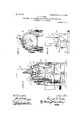
- Fig. 6 is a longitudinal sec- Fig. 7 is-an encross section on line 88 in Fig. 1.
- Fig. 9 is prises a bed or body A and a drum saw B mounted thereon. Saidsaw has a horizontal shaft I) mounted in bearings 11 and provided with a belt pulley b by which the saw is provided'with a straight guide way or, throat c in which the-board X feeds downwardly.
- the said drill has a bit (1 and a drive pulley d, and is mounted to rotate in bearings d,
- rangenien't is such that the cleat' drops down as soon as it is sawed-off; In this way the hopper feeds the board by-gravity as fast asthe cleats drop from the lower "end thereof.
- Fig. 10 w i is a detail front elevation of the hopper or What I claim as my invention is:
- a machine for making basket cover cleats comprising a saw; a drill dis osed above the saw, a vertically disposed andhorizontally reciprocating hopper provided with means for sup orting a board vertically with the lower end thereof extendin “below the edge of the "saw a distance equa to the width desired for the cleats, and means for reciprocating the said hop er toward and away from the said saw and drill, said'hoperadapted to feed the board by gravity-as ast as the drilled cleats are cut off and dropped from the lower end thereof.
- a machine .for maki basket cover cleats comprising a saw, ad disposed above the saw, means for rotating the saw and drill about horizontal non-coincident axes, avertically disposed and horizontally reciprocating be per grovided with means for supporting aoar vertically with the lower end thereof extending below the edge of the saw a distance equal to the width desired for the cleats, means for reciprocating the said hoppertoward' and away from the said saw and dfill', and'a ir argues for thejbottom of the ho per, said hopper adapted-t feed the thereof, a vertically diSPOSed -8Dd -li01iZO D- tally reciprocating 110 per fprovided with means forsup ortmg a oardyertically with the lower'en thereof extending "below the- ;edge' of the sawa distance equal; to thewidth desired for the.-cleats,.-meansfor reciprocating the said: ho
- .the cleats a bevel; said hopper adapte to feed the board'by gravityes fast 'asthe drilled cleats are cutoff. and dropped from the lower end .thereofl 25,-above the saw, a pair of. arches supporting;
- a machine for'making basket cover cleats comprising a saw, a drill disposed above the SaW, the said saw being in the form o'fa cylinder having the curvaturedesired for the inner and outer sides of the cleats, a vertically disposed and horizontally reciprocating shopper provided with means for supportinga oard vertically with the lower endthereof extending below the edge pf the saw a distance equal to the Width desired for the cleats, means for reciprocating f the said hopper toward and away from the said saw and drill, anda frame having guides for the hopper and bearings for the various y o erativeparts, said hopper adapted to feed 4.
- a machine for making basket cover. cleats comprising a saw;- a drill disposed t e'iboard byflgravity as fast as the drilled cleats are exit of and dropped from the lower vend thereoi,
Landscapes
- Engineering & Computer Science (AREA)
- Mechanical Engineering (AREA)
- Processing Of Stones Or Stones Resemblance Materials (AREA)
Description
R. B. FULLER. MACHINE FOR MAKING OLEATS, FOR BASKET oovmzs.
' APPLICATION FILLED APILZQ, 1907.
PATENTED MAY 26, 1908'.
4 SHEETS-SHEET 1.
H's-lawman. .PATBNTEDMA-ms, 1908.
MACHINE FOR MAKING GLEATS POR'BASKET covsss. APPLICATION rmm' APR. 2 1907.
4 SHEETS-SHEET 2.
PATENT-ED MAY 26, 1908.
R. B. FULLER. MACHINE, FOR MAKING OLEATS FOR BASKET covmzs.
' APPLICATION FILED APR. 29, 1907.
4 SHEETS-SHEET 3.
No. 888,990. PATENTED-MAY 26, 1908. R. B. FULLER.
MACHINE FOR MAKING CLEATSPOR BASKET-COVERS. APPLIGATION FILED Arnfiza, 1907;
4 SHEETS-SHEET 4.
" drilling of the tion on line 6 6 Fig. 2.
larged detail view of the drill. Fig. 8 is a 'driven.
UNITED STATES; PATENT OFFICE;
' RUSSELL B. FULLER, or EvAnsyiLLE, INDIANA.
micmim so; We pri rsrdasasxar-cowins.
specificatioli of Letters Patent raten eana ee, loos.
Application filed April 2 1907. Serial mam 29o.
To all whom it may concern: Be itfk-nown that I, RUSSELL B. FULEEEE citizen of the United States -of America, and resident of Evansville, Vanderburg county, Indiana, have inventeda certain new jand useful Improvement in Machines for Making Cleats'for Basket-Covers, of which the fol-- lowing is a specification." H
My invention contemplates-amachine for cuttin and drilling the cleats of baske covers. hese covers are of'the kind in which two end cleats are connected by slats. Covers of this character are commonly used for grape or other fruit baskets, and are held in place by fiexible'wiresor attaching devices.
properly cut andshaped,
he .cleatsmust" be and it is desirable t at they bedrilled toreceive the Wires or attaching devices by which the covers are secured to the baskets. By my inventionthe cutting or shaping the cleats are alldone in one and the same machine.
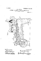
In the accompanying drawingFigure ,1
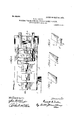
is .a side elevation of a m'achine' embodying the principles of my invention; Fi 2 is a,
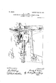
lan of the same. Fig's. 3, '4' and. 5 s ow the oard and-the way in which the 'cle'at's are cuttherefrom. Fig. 6 is a longitudinal sec- Fig. 7 is-an encross section on line 88 in Fig. 1. Fig. 9 is prises a bed or body A and a drum saw B mounted thereon. Saidsaw has a horizontal shaft I) mounted in bearings 11 and provided with a belt pulley b by which the saw is provided'with a straight guide way or, throat c in which the-board X feeds downwardly.
has its lower end pivoted at c an its upper end suitably connected with the said hopper C.,- Said lever is connected by a itman c with an eccentric device 0'', by whic the said hopper is given a reciprocating motion toward and away from the saw B and drill D.
The said drill has a bit (1 and a drive pulley d, and is mounted to rotate in bearings d,
which latter are supported on a pair of arches that s an the frame above the saw. Thus the drill rotates about a horizontal I Said bit d is held in place in the A hp 0? on An inclined hopper or guide C is rectly above the drum saw-,which latter also rotates about a horizontal axis, thesaw and the drill both facing" toward the hop v I body of the drill by the set screw d.
perC
.- 'When the hopper moves forward the saw 1 B cuts ofithe lower end of the board, andat the same time the drill pierces the board immediately above the cut madeby the saw.
The next time the hopper moves forward the' saw cuts off a'drill cleat, and the end of the boardis-drilled for the next cleat'., In this way a'finished cleat is cut-off and the f drilling done forthe next cleat each time the hopper moves-f forward. f It be under-:
stood that the cleatscanjbe drilled either entirely or on lliy partially through the thickness ,j
e inclination of the. hopper gives"* thereof.
the proper-L ntto the'convex-out'er side,
and to the'concave inner side, of each cleat. f1L 1lo(p eror any other means supports the he in position, and the ar-.
rangenien't is such that the cleat' drops down as soon as it is sawed-off; In this way the hopper feeds the board by-gravity as fast asthe cleats drop from the lower "end thereof.
.Thev board, whenit feeds, alwaysextends below the ed e of the 'saw' a distance equal to the width for the cleats. The curvature of the saw is the same as that of the in-- her and outer sides of each cleat. a'cross section on line 99 in Fig. 1. Fig. 10 w i is a detail front elevation of the hopper or What I claim as my invention is:
1. A machine for making basket cover cleats, comprising a saw; a drill dis osed above the saw, a vertically disposed andhorizontally reciprocating hopper provided with means for sup orting a board vertically with the lower end thereof extendin "below the edge of the "saw a distance equa to the width desired for the cleats, and means for reciprocating the said hop er toward and away from the said saw and drill, said'hoperadapted to feed the board by gravity-as ast as the drilled cleats are cut off and dropped from the lower end thereof.
2. A machine .for maki basket cover cleats, comprising a saw, ad disposed above the saw, means for rotating the saw and drill about horizontal non-coincident axes, avertically disposed and horizontally reciprocating be per grovided with means for supporting aoar vertically with the lower end thereof extending below the edge of the saw a distance equal to the width desired for the cleats, means for reciprocating the said hoppertoward' and away from the said saw and dfill', and'a ir argues for thejbottom of the ho per, said hopper adapted-t feed the thereof, a vertically diSPOSed -8Dd -li01iZO D- tally reciprocating 110 per fprovided with means forsup ortmg a oardyertically with the lower'en thereof extending "below the- ;edge' of the sawa distance equal; to thewidth desired for the.-cleats,.-meansfor reciprocating the said: ho per-*toward and-away from the said saw an drill andgnidesforsupporting thehopper in an inclined position to; ive
.the cleats a bevel; said hopper adapte to feed the board'by gravityes fast 'asthe drilled cleats are cutoff. and dropped from the lower end .thereofl 25,-above the saw, a pair of. arches supporting;
per provided iwithfme'ansfor supporting a. oard vertically with the lower end' thereof extending below-the ed e of the saw a distance equal to the wi th desii'ed for thecleats, means for reciprocating the said hop --v per toward-- and away from the said saw and drill, and a. frame-having side members in-. fclosing peer and arches are supported, .saidhopper-f 'Bdfi tedto feed the board: by gravity, as fast as t e drilled cleats are'cut ofl and dropped e saw and upon which the said-hop from the lower'en'd thereof,
:5; A machine for'making basket cover cleats, comprising a saw, a drill disposed above the SaW, the said saw being in the form o'fa cylinder having the curvaturedesired for the inner and outer sides of the cleats, a vertically disposed and horizontally reciprocating shopper provided with means for supportinga oard vertically with the lower endthereof extending below the edge pf the saw a distance equal to the Width desired for the cleats, means for reciprocating f the said hopper toward and away from the said saw and drill, anda frame having guides for the hopper and bearings for the various y o erativeparts, said hopper adapted to feed 4. A machine for making basket cover. cleats, comprising a saw;- a drill disposed t e'iboard byflgravity as fast as the drilled cleats are exit of and dropped from the lower vend thereoi,
the drill shaft above thesaw, a vertically disposed and horizontallyiireciproeating hop- Signed by meat Evansville,- -Ind., this 22nd day of April, 1907,
RUSSELL B. FULLER.
Priority Applications (1)
| Application Number | Priority Date | Filing Date | Title |
|---|---|---|---|
| US37079007A US888990A (en) | 1907-04-29 | 1907-04-29 | Machine for making cleats for basket-covers. |
Applications Claiming Priority (1)
| Application Number | Priority Date | Filing Date | Title |
|---|---|---|---|
| US37079007A US888990A (en) | 1907-04-29 | 1907-04-29 | Machine for making cleats for basket-covers. |
Publications (1)
| Publication Number | Publication Date |
|---|---|
| US888990A true US888990A (en) | 1908-05-26 |
Family
ID=2957422
Family Applications (1)
| Application Number | Title | Priority Date | Filing Date |
|---|---|---|---|
| US37079007A Expired - Lifetime US888990A (en) | 1907-04-29 | 1907-04-29 | Machine for making cleats for basket-covers. |
Country Status (1)
| Country | Link |
|---|---|
| US (1) | US888990A (en) |
Cited By (1)
| Publication number | Priority date | Publication date | Assignee | Title |
|---|---|---|---|---|
| US2753899A (en) * | 1951-11-19 | 1956-07-10 | William M Murfin | Annular power saw |
-
1907
- 1907-04-29 US US37079007A patent/US888990A/en not_active Expired - Lifetime
Cited By (1)
| Publication number | Priority date | Publication date | Assignee | Title |
|---|---|---|---|---|
| US2753899A (en) * | 1951-11-19 | 1956-07-10 | William M Murfin | Annular power saw |
Similar Documents
| Publication | Publication Date | Title |
|---|---|---|
| US888990A (en) | Machine for making cleats for basket-covers. | |
| NO855314L (en) | Lumber and Woodcutters | |
| US144938A (en) | Improvement in machines for cutting veneers | |
| US198404A (en) | Improvement in machines for cutting veneers | |
| US410784A (en) | Machine for | |
| US375887A (en) | Clapboard-machine | |
| US1778321A (en) | Sawing machine for tree felling and log cutting | |
| US856767A (en) | Handhold-forming machine. | |
| US121093A (en) | Improvement in machines for boring and mortising blind-slats | |
| US854116A (en) | Toothpick-machine. | |
| US142096A (en) | Improvement in stone-channeling machines | |
| US959386A (en) | Machine for recessing shoe parts. | |
| US323453A (en) | Machine for making clothes-pins | |
| US203928A (en) | Improvement in machines for preparing wood fiber for paper-pulp | |
| US420902A (en) | Hoop-machine | |
| US673378A (en) | Mortising-machine. | |
| US174056A (en) | Improvement in machines for cutting veneers | |
| US73214A (en) | Improvement in machines foe sawing laths | |
| US559241A (en) | Stump-cutting machine | |
| US286221A (en) | Machine for cutting key-seats | |
| US572207A (en) | Gear-cutting machine | |
| US853908A (en) | Adjustable boring and sawing machine. | |
| US1133902A (en) | Barn-framing machine. | |
| US124137A (en) | Improvement in clothes-pin machines | |
| US211715A (en) | Improvement in barrel-hoop machines |